Week 9:- 2D Detailing Challenge
- DRAWING TEMPLATES: A drawing template is sheet layout inside on which 2D drawing views are made.
A drawing template is usually consist of offset Border line having grid references and unit measurement references mark.
A title box is also present at lower right side which contains information regarding Sheet name, Sheet size, Customer name, projection view symbol, drawing scale,etc.
Sheet sizes: A0 (841 x 1189), A1 (594 x 841), A2(420 x 594), A3 (297 x 420), A4 (210 x 297) [all sizes in mm]
Title box content: (The size as recommended by BIS is 185mm x 65mm)- Name of customer
- Drawing Title
- Scale
- Symbol for the method of projection
- Drawing number
- Initials with dates of persons who have designed, drawn, checked and approved.
- No. of sheet and total no. of sheets of the drawing of the object
ANGLE OF PROJECTION: The angle at which an object is represented in a two-dimensional engineering drawing.
Engineering drawings are used to communicate detailed information about a design, including dimensions, shapes, and relationships between different parts of a structure or object. These drawings are often created using various projection methods, such as orthographic projection or isometric projection.-
Orthographic Projection Angles: In orthographic projection, objects are represented using multiple views (front, top, side, etc.).
- When the projectors are parallel to each other and also perpendicular to the plane, the projection is called Orthographic projection.
- The two planes employed for the purpose of orthographic projection are called Reference planes. They intersect each other at right angles.
- Vertical plane (in front of observer) is denoted by letters V.P. It is also called Frontal plane.
The other plane which is Horizontal plane is known as H.P. - The projection on V.P. is called Front view or Elevation.
- The projection on H.P. is called Top view or Plan.
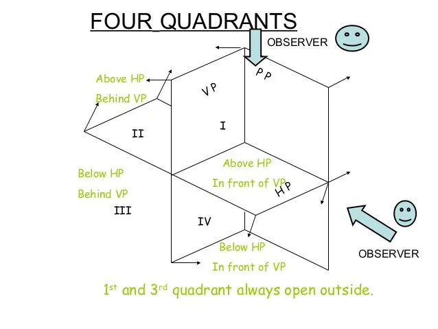
- The planes of projection forms four quadrants. The planes are assumed to be transparent.
-
Isometric Projection Angles: Isometric projection is a form of pictorial projection that shows three sides of an object in a single view. This projection uses specific angles to create the illusion of depth without distortion. The angles used in isometric projection are typically 120 degrees between the axes.
-
Sectional Views: When drawing sections of an object to show its internal features, the angle of projection for the section lines can influence how clearly the interior details are represented.
-
- In First angle projection, the object is placed in the first quadrant (top-right) of the imaginary box enclosing the object. The six principal views (front, top, bottom, right, left, and rear) are projected onto the adjacent planes of the box. The front view is placed on the bottom and the top view is placed on the top plane. The side views are placed on the corresponding side planes. This method of projection is now recommended by BIS from 1991 hence it is used in India, Europe and rest of world.
In Third angle projection, the object is placed in the third quadrant (bottom-left) of the imaginary box. The front view is projected onto the bottom plane, and the top view is projected onto the top plane. The side views are projected onto the corresponding side planes, as in first angle projection. This method of projection is used in USA and Canada.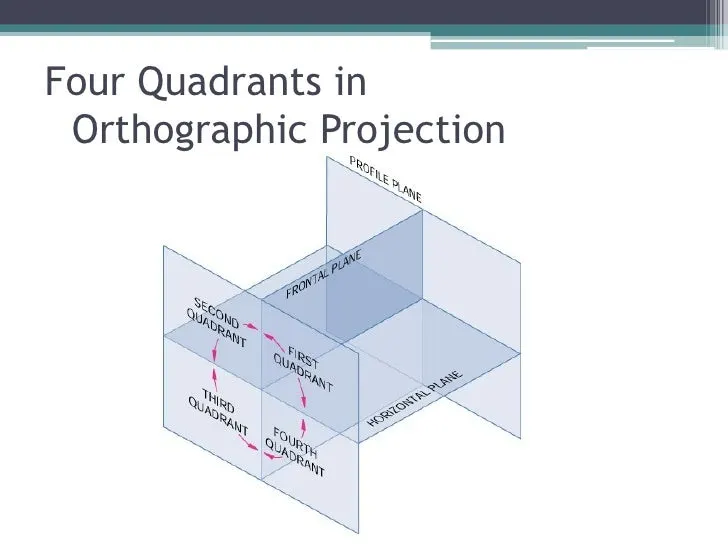
As per rule of projection when horizontal plane is rotated 90 degree in clockwise direction, top and front view will overlap. Overlapping projection views create confusion in the drawing. Therefore 2nd angle projection system is not used. Therefore fourth angle projection is also not used.
To sum up, Because of the overlapping of front and top views 2nd and 4th angle projections are not used. - GD&T (Geometric dimensioning and tolerances): It is a symbolic language used in engineering and manufacturing to communicate precise specifications for the size, shape, orientation, and location of features on a part or component.
GD&T uses a set of symbols, terms, and rules defined by international standards (ASME Y14.5 in the United States, ISO 1101 internationally) to specify the following aspects:
-
Form: Describes the overall shape of a feature, such as flatness, straightness, circularity, and cylindricity.
-
Orientation: Defines the angular relationship between features, including parallelism, perpendicularity, and angularity.
-
Location: Specifies the position of features in relation to a datum reference frame, using controls like position, concentricity, and symmetry.
-
Profile: Describes the allowable variation of a feature's surface within a specified tolerance zone.
-
Runout: Specifies the allowable variation in the form and location of a feature's surface as it rotates.
-
- SYMBOLS IN GD&T:
 Maximum material condition (MMC) : A factor of safety that contains the greatest amount of material, yet remains within tolerance zone. ex: Largest pin dia and smallest hole size.
 Least material condition (LMC) : A factor of safety that contains the Least amount of material within tolerance zone. ex: smallest pin dia and Largest hole size.
 Projected Tolerance Zone : Used when a tolerance zone applies outside the boundaries of the physical part.
 True position : Controls how far a feature can deviate from a given location.
 Straightness : A tolerance given that defines how far from a perfect line a feature can be. A 2D (line) requirement.
 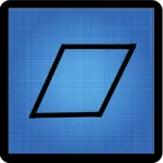 Flatness : Similar to straightness but the callout applies over the entire surface (plane).
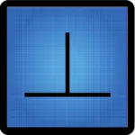 Perpendicularity : Defines the maximum allowed deviation of a feature from 90°.
 Parallelism : Describes two features that are equally distanced from each other over their entire surfaces.
 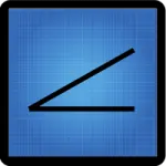 Angularity : Angularity is the allowed deviation from a theoretically perfect feature at a specified angle other than 90° or 180° from another feature.
 Circular Runout : Controls the runout of a rotated circular at any single location on the feature.
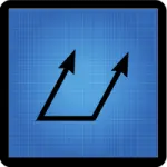 Total Runout : Controls the runout of a rotated circular at all locations on the feature.
-
 Profile of a Line : A tolerance that identifies how close to a specified design a feature is at specific cross section.
  Profile of a Surface : A tolerance that identifies how close to a specified design a whole feature is.
 Circularity : A tolerance that defines how round a feature must be at a single location.
 Cylindricity : Similar to circularity but it applies over the entire cylinder instead of at a single point.
 Concentricity : A requirement that the centerline or axis of two features are located within a specified tolerance of each other.
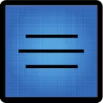 Symmetry : Controls the location of a feature such as a slot to a datum.
 Regardless of Feature size (RFS) : The tolerances do not change based on the size of the features. This is an older symbol that is no longer used. This condition is assumed unless specified otherwise now.
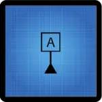 Datum : A feature which is used for location and measurement of other features.
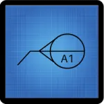 Movable Datum Target : Identifies datum targets that may be shifted in a specified direction.
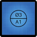 Datum Target : The top section is the size and shape of the target area. The lower section lists the identifying letter and number.