Week 9:- 2D Detailing Challenge
Week 9:- 2D Detailing Challenge
1) What are the Drawing templates?
Drawing templates are typically created by a user or organization to reflect their specific drafting standards and
requirements. Once created, these templates can be used as a starting point for new drawings, allowing the user to
quickly set up the drawing with the appropriate settings and formatting. Many computer-aided design (CAD) software
programs offer the ability to create and save drawing templates for future use.

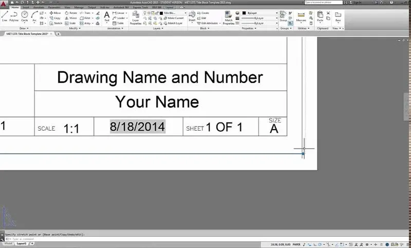
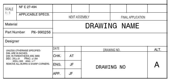
Drawing templates contains a lot of information about the drawing as given below:
* Page size and orientation
* Drawing scale and units of measurement
* Grid and snap settings
* Layer settings and color schemes
* Text styles and font types/sizes
* Title block, including fields for title, author, date, and other information
* Company name
* Part name or code
* Project name or code
* Drawn by, date & sign
* Checked by, date & sign
* Approved by, date & sign
* Material, Density & other parameters if required
* Border or frame around the drawing
* Watermarks or other branding elements
* Revision history or change log
* Project-specific notes or instructions
* Copyright information or disclaimers
The specific elements included in a drawing template may vary depending on the software being used and
the preferences of the user or organization creating the template.
2) What do you understand by Angle of projection?
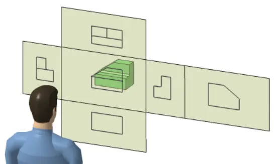
In engineering drawing, the angle of projection refers to the angle at which the object being drawn is projected onto a
two-dimensional plane. The angle of projection is typically specified as either a first angle or third angle projection.
The angle of projection refers to the angle at which the object is projected onto the plane of projection. Specifically,
it refers to the angle between the plane of projection and the line of sight of the observer. The angle of projection is
typically specified as either a first angle or third angle projection, as I mentioned in my previous answer.
the plane of projection and angle of projection help to determine the position and orientation of the views in a drawing,
as well as the overall layout of the drawing sheet. By specifying these parameters, engineers and designers can create
accurate and consistent representations of complex objects, which can be used for manufacturing, assembly,
and other purposes.
3) What is the First angle & Third angle projection? and why can't we use the 2nd and 4th angle of projection?
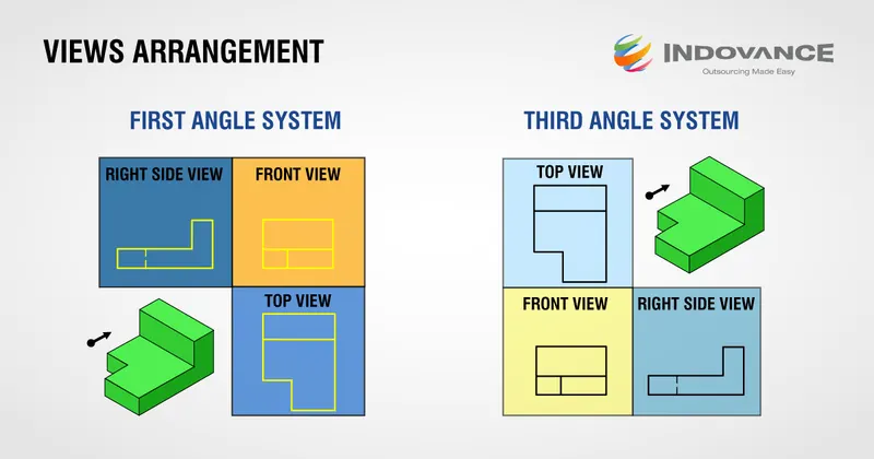
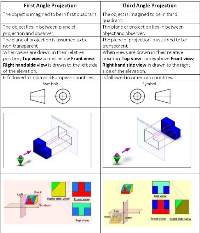
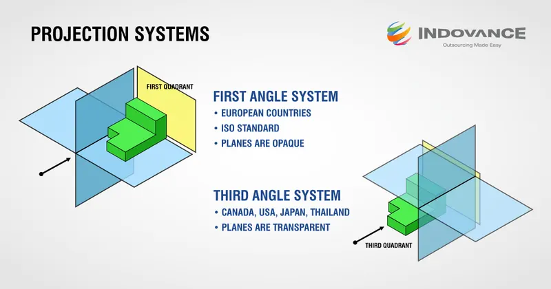
First angle projection and third angle projection are methods used in technical drawing to represent a three-dimensional
object in a two-dimensional format. These methods are used to create orthographic projections, which are views of the
object from different angles.
In first angle projection, the object is placed in front of the projection plane, and the views of the object are projected
onto the planes behind it. The observer views the object from behind the projection plane.
In third angle projection, the object is placed behind the projection plane, and the views of the object are projected
onto the planes in front of it. The observer views the object from in front of the projection plane.
The reason why we can't use the 2nd and 4th angle of projection is first of all it will over lap one on another and next is
they are not recognized as standard
practices in technical drawing. They were used in some countries in the past, but they are no longer widely used.
The first and third angle projections are the two standard methods used in technical drawing, and they are
recognized and accepted by international standards organizations such as ISO and ANSI. Using non-standard methods
can lead to confusion and misinterpretation of technical drawings.
4) What is GD&T? What are the benefits of GD&T?
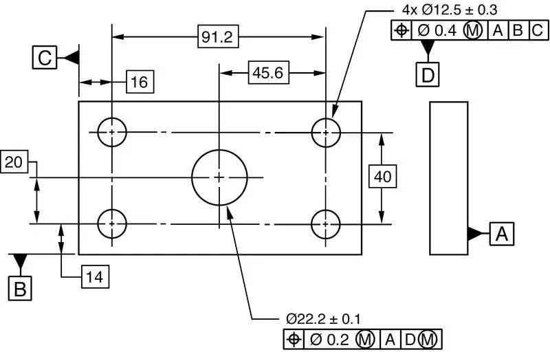
GD&T stands for Geometric Dimensioning and Tolerancing, which is a symbolic language used to define and communicate
the design, manufacturing, and inspection requirements of a product.
It is a system of symbols and rules used to specify the size, shape, orientation, and location of features on a part or
assembly. GD&T provides a precise and unambiguous method of defining the geometric requirements of a part,
which helps to ensure that the part is manufactured correctly and functions as intended.
The benefits of GD&T include:
I) Improved communication: GD&T provides a standardized language for communicating design, manufacturing,
and inspection requirements, which helps to reduce ambiguity and misinterpretation.
II) Increased design flexibility: GD&T allows for greater design flexibility by specifying the desired form, fit, and function
of a part, rather than relying on traditional linear dimensions.
III) Improved quality control: GD&T provides a precise and unambiguous method of defining the geometric requirements
of a part, which helps to ensure that the part is manufactured correctly and functions as intended.
IV) Reduced manufacturing costs: GD&T allows for tighter tolerances, which can help to reduce the number
of rejected parts and improve manufacturing efficiency.
V) Enhanced inspection capabilities: GD&T provides a standardized method for inspecting parts,
which helps to ensure that parts meet the desired specifications.
Overall, GD&T is a powerful tool for ensuring that parts are manufactured correctly and function as intended. By using
GD&T, manufacturers can improve communication, increase design flexibility, improve quality control,
reduce manufacturing costs, and enhance inspection capabilities.
5) Explain all the symbols used in GD&T?
GD&T (Geometric Dimensioning and Tolerancing) uses a set of 14 symbols to represent the design, manufacturing, and
inspection requirements of a part. Here is an explanation of all 14 symbols used in GD&T:
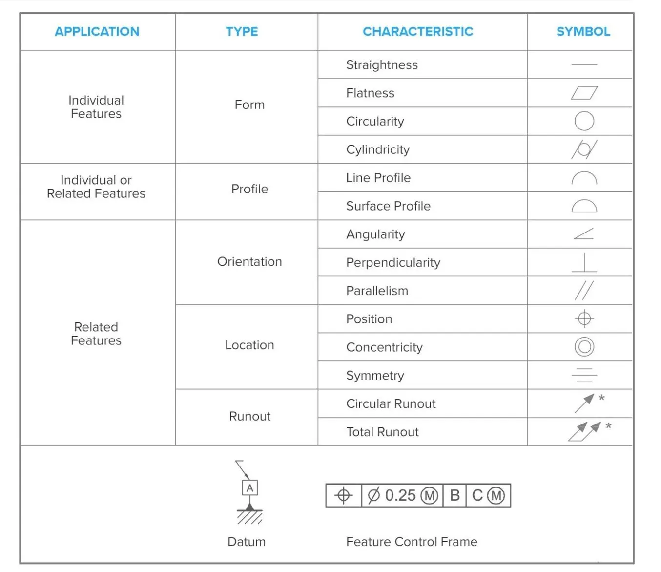
Certainly! GD&T (Geometric Dimensioning and Tolerancing) uses a set of 14 symbols to represent the design, manufacturing, and inspection requirements of a part. Here is an explanation of all 14 symbols used in GD&T:
1) Straightness : This symbol represents a straight line and is used to specify the form of a feature. It is represented
by a short, horizontal line placed above the feature.
2) Flatness : This symbol represents a flat surface and is used to specify the form of a surface. It is represented by a
short, horizontal line with two parallel lines above it.
3) Circularity : This symbol represents a circle and is used to specify the form of a feature. It is represented by a circle
with a short, horizontal line placed above it.
4) Cylindricity : This symbol represents a cylinder and is used to specify the form of a feature. It is represented by a
cylinder with a short, horizontal line placed above it.
5) Profile of a Line : This symbol is used to specify the shape of a feature that is not a surface. It is represented by
two parallel lines with the profile of the feature drawn between them.
6) Profile of a Surface : This symbol is used to specify the shape of a surface. It is represented by a square with the
profile of the surface drawn inside it.
7) Angularity : This symbol is used to specify the angle of a feature. It is represented by a "V" shape with a numerical
value indicating the allowable angle deviation.
8) Perpendicularity : This symbol represents a 90-degree angle and is used to specify the orientation of a feature.
It is represented by a square with a short, vertical line placed above it.
9) Parallelism : This symbol represents two lines that are parallel to each other and is used to specify the orientation
of a feature. It is represented by two parallel lines with a short, vertical line placed above them.
10) Position : This symbol represents the location of a feature and is used to specify the location and allowable tolerance
zone of the feature. It is represented by a crosshair with a numerical value that indicates the distance and direction
from a reference point.
11) Concentricity : This symbol represents two circles that share a common center point and is used to specify the
relationship between two features. It is represented by two circles with a short, horizontal line placed above them.
12) Symmetry : This symbol represents a mirror image and is used to specify the symmetry of a feature. It is represented
by two lines with a short, vertical line placed above them.
13) Runout : This symbol is used to specify the total variation of a surface from the specified true shape. It is represented
by a circle with a spiral line drawn inside it.
14) Total Runout : This symbol is used to specify the total variation of a feature's entire surface or axis. It is represented
by a circle with two spiral lines drawn inside it.
These are the 14 symbols used in GD&T. Each symbol is used to specify a different aspect of a part's design,
manufacturing, and inspection requirements. By using these symbols, engineers and manufacturers can ensure
that parts are made to the required specifications and function as intended.
Feature Control Frame (FCF)
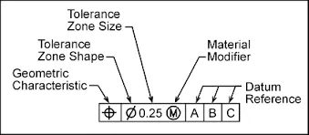
Feature Control Frame (FCF) is a rectangular box that contains the geometric control information for a feature or a
group of features on a part. The FCF is used to specify the allowable tolerances on a feature's size, location, orientation,
and form, as well as the method for inspecting the feature.
The FCF consists of four parts:
I) Geometric Characteristic Symbol: This is one of the 14 GD&T symbols that represent a geometric control of a feature.
It is placed in the upper left corner of the FCF and indicates the type of geometric control applied to the feature.
II) Tolerance Zone: This is a graphical representation of the allowable deviation from the perfect form, size, orientation,
or location of the feature. The tolerance zone is represented by a rectangular box that surrounds the feature control
symbol and has dimensions specified in the FCF.
III) Datum References: These are specific features or points on the part that are used as reference surfaces or points
for measuring the feature. Datum references are represented by capital letters (A, B, C, etc.) and are located in the
FCF next to the tolerance zone.
IV) Material Condition Modifier: This indicates the condition of the material when the feature is inspected. It is
represented by a small flag symbol in the FCF and may be used to indicate if the feature is inspected in a maximum
material condition, a minimum material condition, or a least material condition.
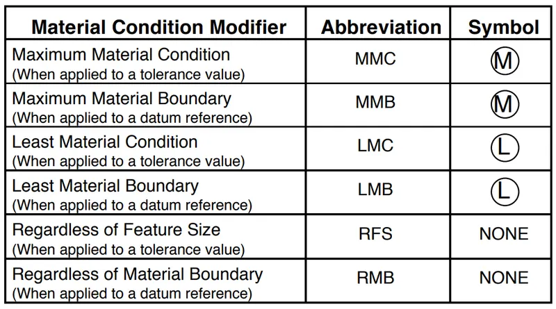
Overall, the FCF is a powerful tool in GD&T that allows engineers and manufacturers to specify the precise tolerances
and inspection methods required for each feature on a part. By using FCFs, parts can be designed, manufactured,
and inspected to ensure they meet the required specifications and function as intended.