Week 8 Worm Gear Challenge
Aim
1. To perform a transient structural analysis on a worm gear assembly
2. To simulate the worm gear model to get results in terms of equivalent stress, equivalent elastic strain and the total deformation.
Procedure
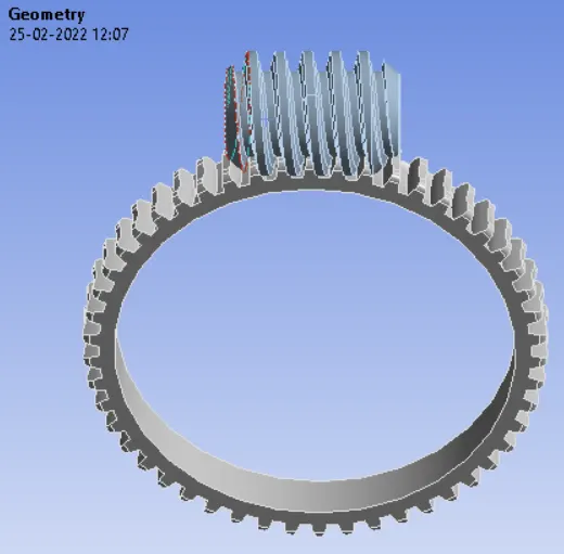
1. Geometry Impart
After opening the ansys workbench, transient structural analysis was selected to perform simulation. The geometry was selected in the deck. The geometry was as below:
2. Material Data
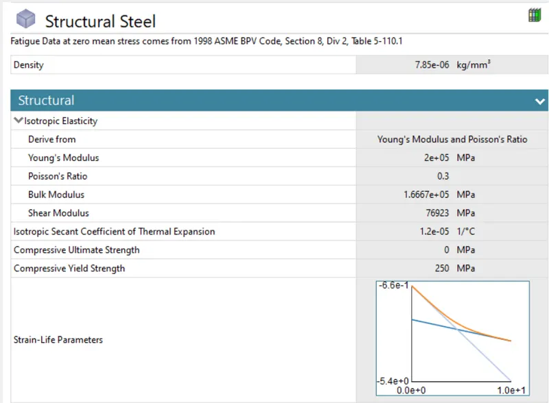
The material used for this simulation was structural steel. The properties of structural steel is shown below:
3. Connections
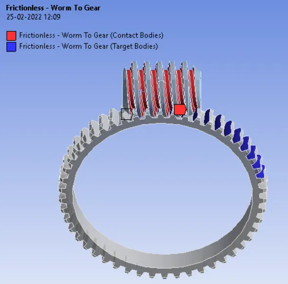
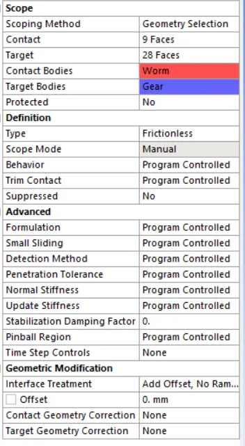
3.1 Frictionless Contact
The frictionless contact was assigned to the gears by selecting the mating faces of two gears as per given image:
3.2 Revolute Joints
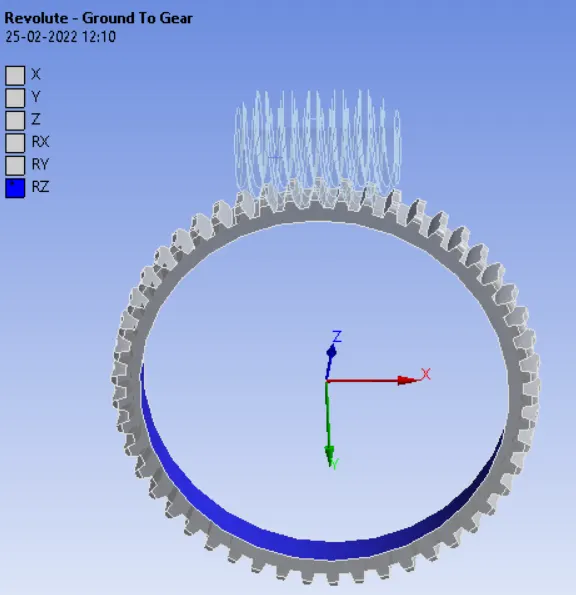
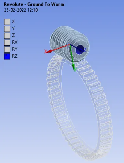
By selecting the internal faces of the two gears, two revolute joints were assigned as per the given image:
4. Mesh Detais
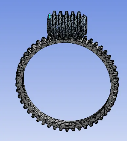
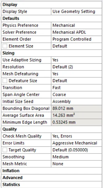
The default element sizing and method was used for meshing the gears.
5. Analysis Settings
Analysis settings are as shown below:
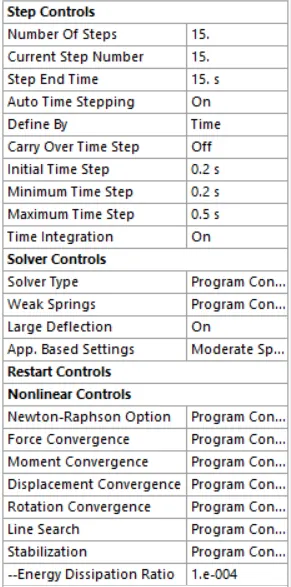
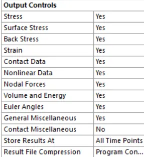
The analysis was done in 15 steps with autotime stepping on. The initial time step and minimum time step was selected as 0.2s. Max time step was 0.5 seconds. Large deflection was on during analysis.
6. Load Details
6.1 Joint Rotation
Load was given to the worm in form of rotation as per given below in 15 steps:
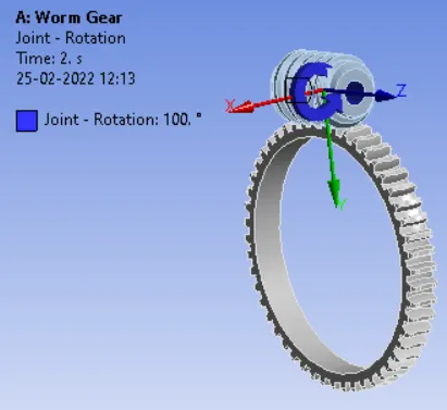

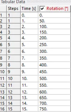
7. Results
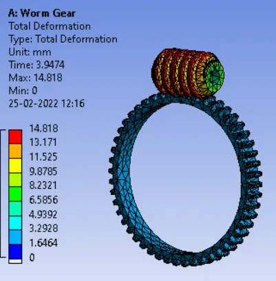
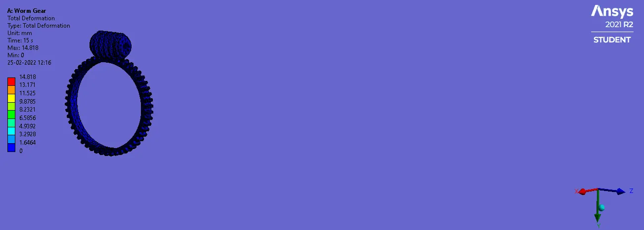
7.1 Total Deformation
7.2 Equivalent Stress
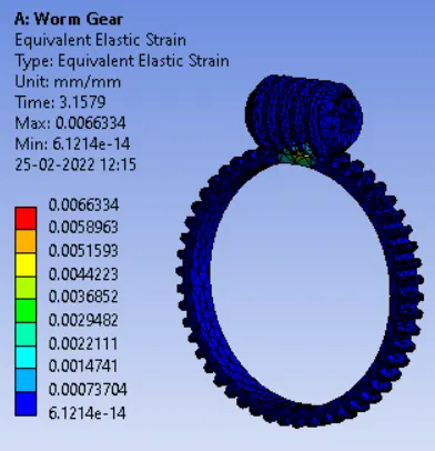
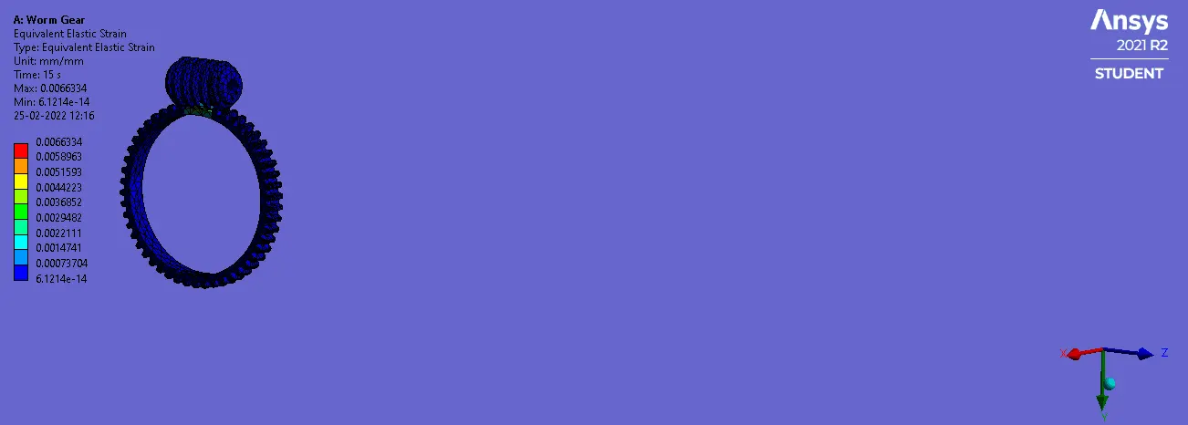
7.3 Equivalent Elastic Strain
Conclusion
1. Simulation was done successfully for the given worm gear using ANSYS WB.
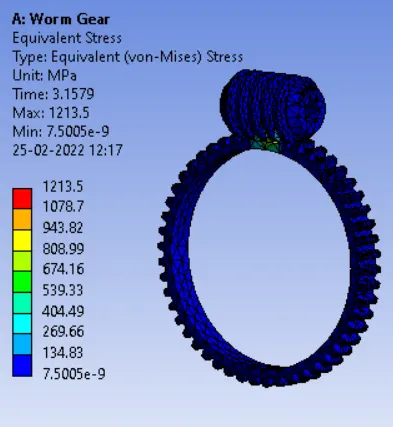
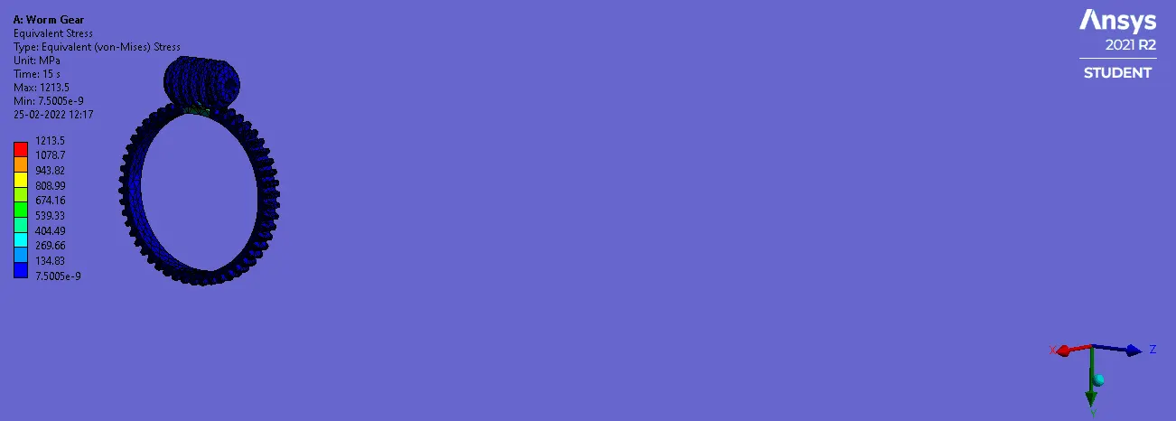
2. From the results, max stress was 1213.5 MPa and max total deformation was 14.818 mm.
3. The max stress developed was greater than the yield strength of material and so that the deformation was just elestic-plastic.