Week 8 Worm Gear Challenge
Stress Concentration on Worm Gear Simulation
OBJECTIVES:
To carry out a Transient Structural Analysis on Worm Gear Simulation for the given materials and determine the stress, deformation, and Plastic strain.
GEOMETRY:
For this project, we have two parts in the assembly named Worm & Gear. The full geometry is shown below.
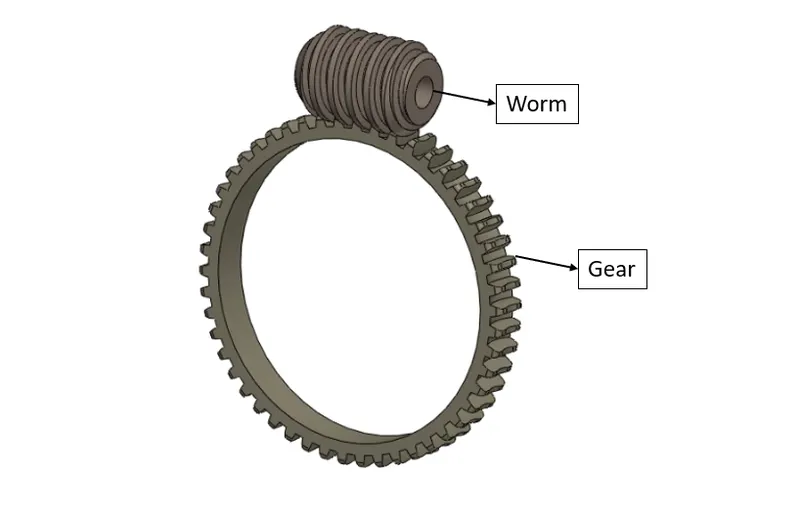
Fig.1 Full Geometry
For the sake of FE Analysis, we will look for stress only in half portion of the gear, this will lead to less computational time, so the gear model was cut in half. The final model for analysis is shown below.
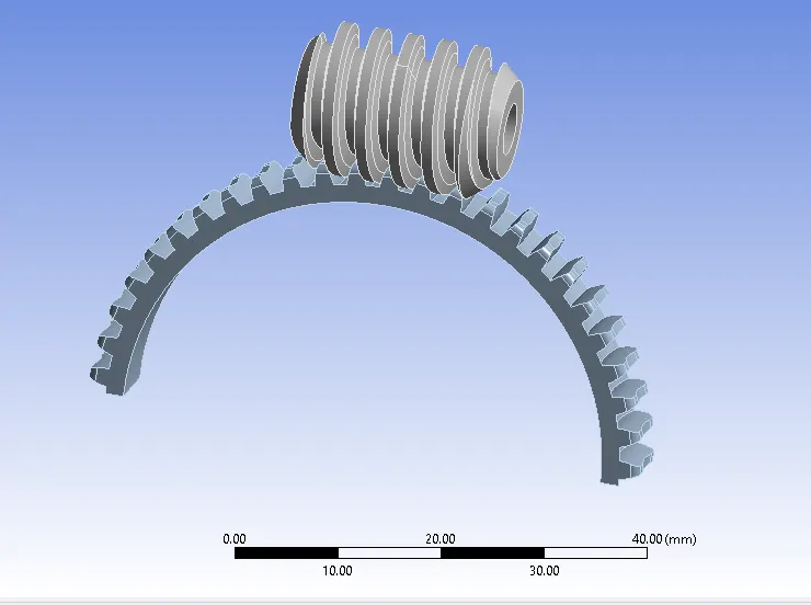
Fig.2 Worm Gear Model for Analysis
MATERIAL:
The Transient Structural Analysis was carried out with the given model. The material used for this analysis was STRUCTURAL STEEL NL and the analysis was carried out using ANSYS Mechanical Enterprise. The model for case-1 was imported to ANSYS Workbench software and is shown in the figure below.

Fig.3 Material Data
Later the material was assigned and the material and its properties used for this analysis are specified below.
|
Material |
Structural Steel |
|
Density |
7.85e-6 kg/mm3 |
|
Young’s Modulus |
2e+5 MPa |
|
Thermal Conductivity |
0.0605 W/mm°C |
|
Specific Heat |
4.34e+5 mJ/kg°C |
|
Tensile Yield Strength |
250 MPa |
|
US/TM |
460 MPa |
|
Components |
Worm and Gear |
MESHING:
Meshing was carried out by DEFAULT Mesh Size with Adaptive Sixing ON Smoothing MEDIUM.
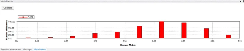
Fig.4 Element Quality
A mesh metric that identifies elements according to their quality was employed and it can be seen that the elements of the lowest quality are minimal. Most of the elements have very high quality in the range of 0.63 to 0.88. Hence, the mesh is of acceptable quality. The meshed model is shown below.
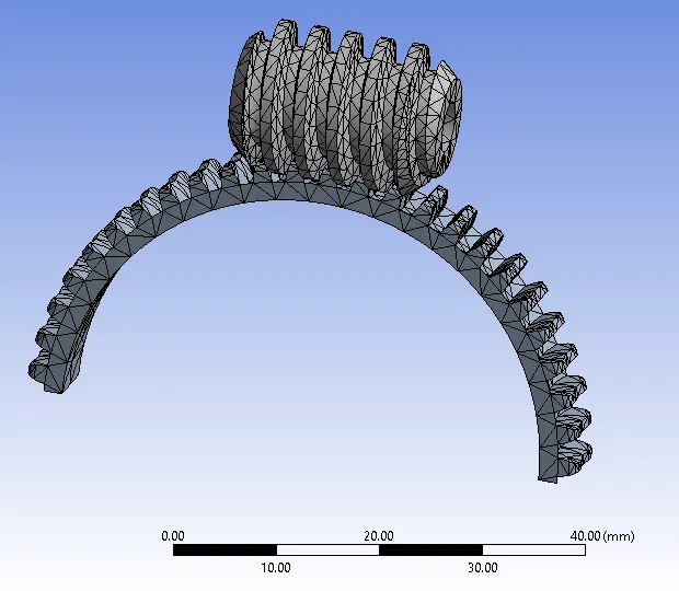
Fig.5 Meshed Model
CONTACT:
The contacts between the Worm and the Gear were specified with a FRICTIONLESS type connection. The contact is set: a) Gear (target), Worm (contact).
JOINTS:
- REVOLUTE Ground Joint: to Gear Inner Cylindrical Face.
- REVOLUTE Ground Joint: to Worm Inner Cylindrical Face.
ANALYSIS SETTING:
15 STEPS ARE USED.
For 1st steps:
- Initial Time Step: 0.2s
- Minimum Time Step: 0.2s
- Maximum Time Step: 0.5s
- Solver Type: Program Controlled
- Weak Spring: Program Controlled
- Large deflection: ON
- Output controls: Set all to YES except Contact Miscellaneous
For 2 to 9 steps:
- Carry Over Time Step: ON
- Minimum Time Step: 0.2s
- Maximum Time Step: 0.5s
- Solver Type: Program Controlled
- Weak Spring: Program Controlled
- Large deflection: ON
- Output controls: Set all to YES except Contact Miscellaneous
BOUNDARY CONDITIONS AND LOAD:
- Joint Load: Revolute – Ground to Barrel
- DOF: Rotation Z
- Type: Rotation
- Magnitude: Tabular Data
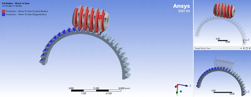
Fig.6 Frictionless Contact
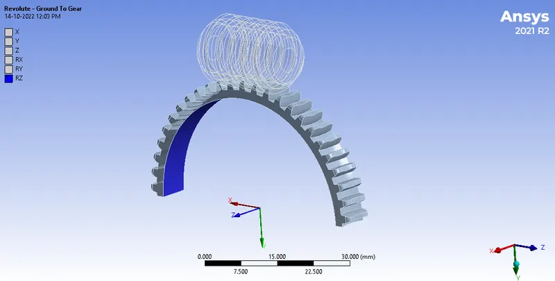
Fig.7 Revolute Ground Joint - Gear
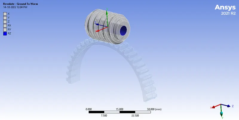
Fig.8 Revolute Ground Joint – Worm
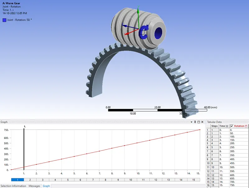
Fig.9 Revolute Joint Load
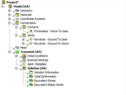
Fig.10 Case Setup
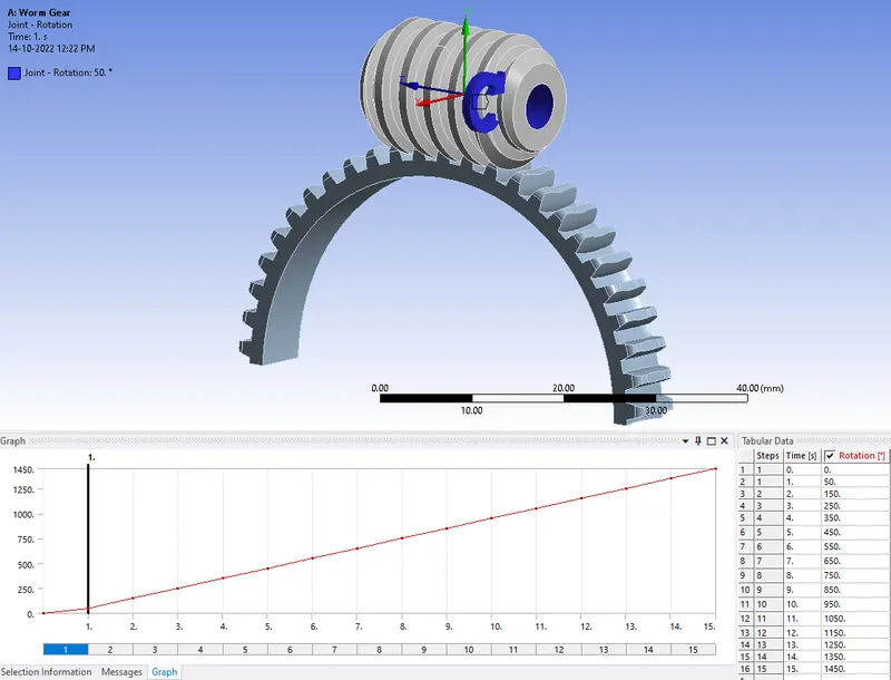
Fig.11 Revolute Joint Load – for 1450° of rotation
RESULTS:
The Total Deformation of the Setup obtained from the analysis is shown below.
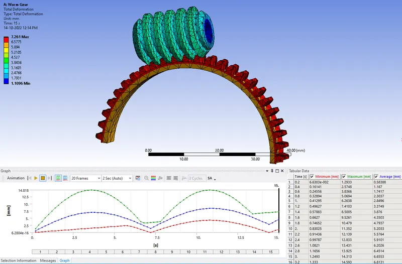
Fig.12 Total Deformation Contour Plot
The Equivalent (Von-Mises) Stress of the Setup obtained from the analysis is shown below.
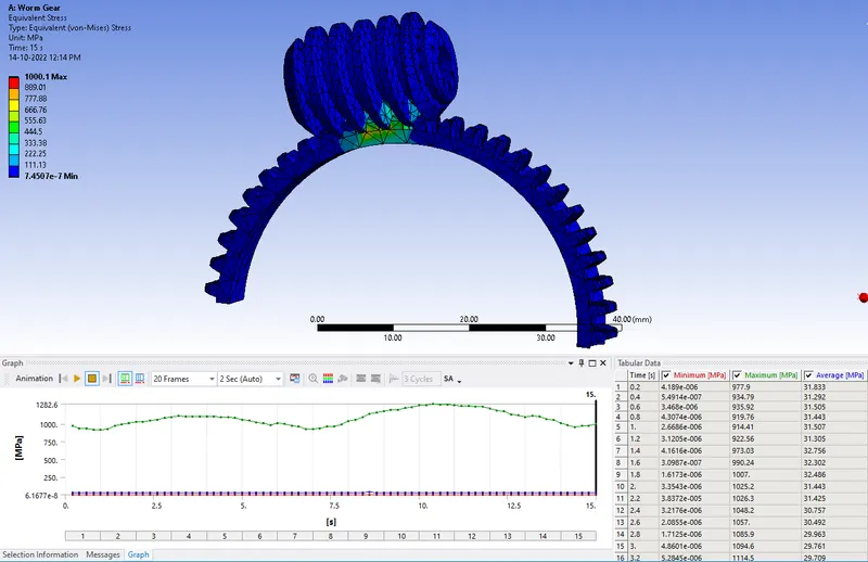
Fig.13 Equivalent Stress Contour Plot
The Equivalent Plastic Strain of the Setup obtained from the analysis is shown below
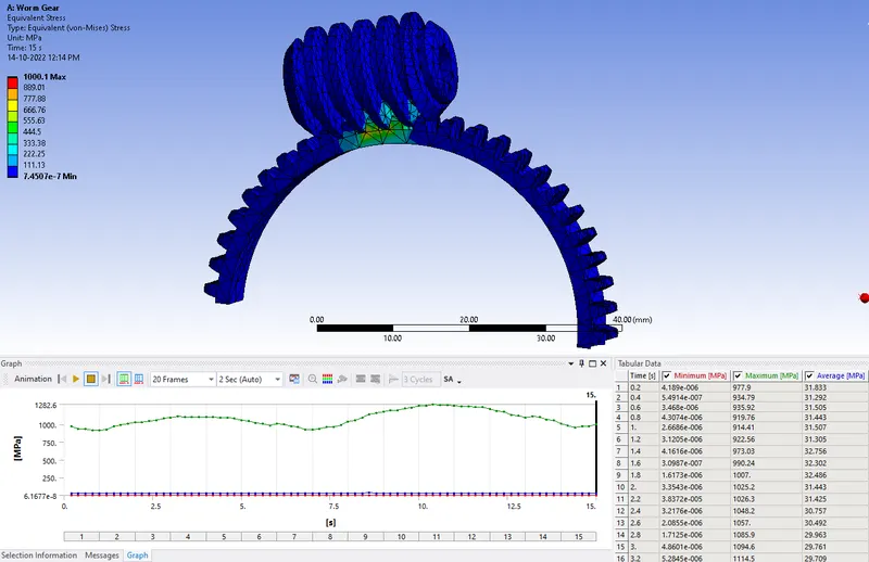
Fig.14 Equivalent Plastic Strain Contour Plot
For Revolute Load - 1450° of rotation
The Total Deformation of the Setup obtained from the analysis is shown below.
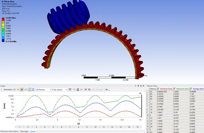
Fig.15 Total Deformation Contour Plot
The Equivalent (Von-Mises) Stress of the Setup obtained from the analysis is shown below.
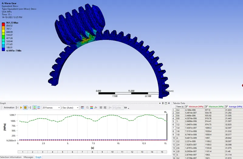
Fig.16 Equivalent Stress Contour Plot
The Equivalent Plastic Strain of the Setup obtained from the analysis is shown below
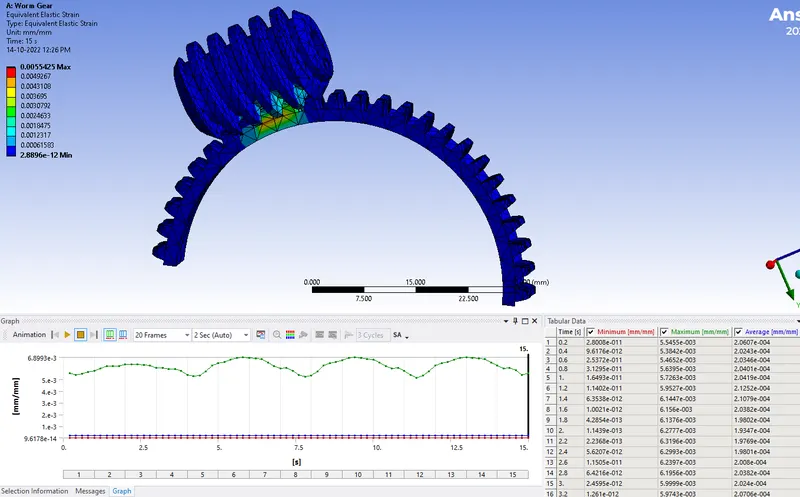
Fig.17 Equivalent Plastic Strain Contour Plot
The simulation was run and the results are tabulated below for 750 degrees of rotation.
|
Output |
Maximum |
Minimum |
|
Equivalent Stress [MPa] |
1282.6 |
6.1677e-8 |
|
Equivalent Plastic Strain [mm/mm] |
6.949e-3 |
5.8729e-13 |
|
Total Deformation [mm] |
14.818 |
6.2804e-16 |
The simulation was run and the results are tabulated below for 1450 degrees of rotation.
|
Output |
Maximum |
Minimum |
|
Equivalent Stress [MPa] |
1299.7 |
9.2585e-9 |
|
Equivalent Plastic Strain [mm/mm] |
6.899e-3 |
9.6178e-14 |
|
Total Deformation [mm] |
14.762 |
6.6303e-2 |
CONCLUSION:
The analysis was run successfully and results were obtained and tabulated.
- The Maximum Stress of the setup was 1282.6 MPa and
- The Maximum Plastic Strain of the Setup was 6.9e-2 mm/mm.
- From both tabular result data, the Stress, Strain, and Total Deformation are quite close/similar.
From the results, we can conclude that the worm and gear assembly should be made out of different materials to minimize stress and pressure and to reduce the loss of efficiency. Generally, the worm and worm gear are used with different materials to reduce friction and for better transmission.
Further, increasing the degree of rotation leads to Un convergence of solution even after changing the mesh size and also the no. of steps in the analysis setting.