Week 8 Worm Gear Challenge
TRANSIENT STRUCTURAL ANALYSIS ON WORM GEAR USING ANSYS WORKBENCH
OBJECTIVE
1. To perform transient structural analysis on a worm gear assembly.
2. To find out Total Deformation, Equivalent Stress, and Equivalent Elastic Strain in the model.
1. THEORY
1.1 Worm Gear:
Worm gear drives are mechanical drives with skewed axes which consist of a worm and a worm wheel. Worm gears are usually used when large speed reductions are needed. The reduction ratio is determined by the number of starts of the worm and number of teeth on the worm gear. But worm gears have sliding contact which is quiet but tends to produce heat and have relatively low transmission efficiency.
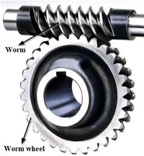
Fig.1.1 Worm gear assembly
As for the materials for production, in general, worm is made of hard metal while the worm wheel is made from relatively soft metal such as aluminum bronze. This is because the number of teeth on the worm wheel is relatively high compared to worm with its number of starts being usually I to 4, by reducing the worm wheel hardness, the friction on the worm teeth is reduced. Another characteristic of worm manufacturing is the need of specialized machine for gear cutting and tooth grinding of worms. The worm gear, on the other hand, may be made with the hobbing machine used for spur gears. But because of the different tooth shape, it is not possible to cut several gears at once by stacking the gear blanks as can be done with spur gears.
The applications for worm gears include gear boxes, fishing pole reels, guitar string tuning pegs, and where a delicate speed adjustment by utilizing a large speed reduction is needed. While you can rotate the worm wheel by worm, it is usually not possible to rotate worm by using the worm wheel. This is called the self-locking feature. The self-locking feature cannot always be assured and a separate method is recommended for true positive reverse prevention.
2. ANALYSIS SETUP
2.1 Geometry:
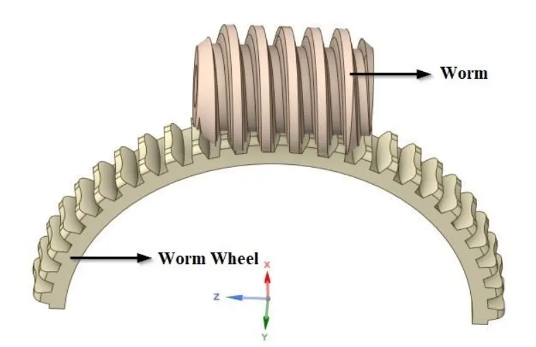
Fig.2.1 3D model of worm gear assembly.
The given 3D model of worm gear assembly is imported into SpaceClaim. It consists of alvorm and worm wheel. To bring the model within the limits of academic version and to reduce the computational time, the worm wheel is cut by half as shown in fig.2.1.
2.2 Material Properties:
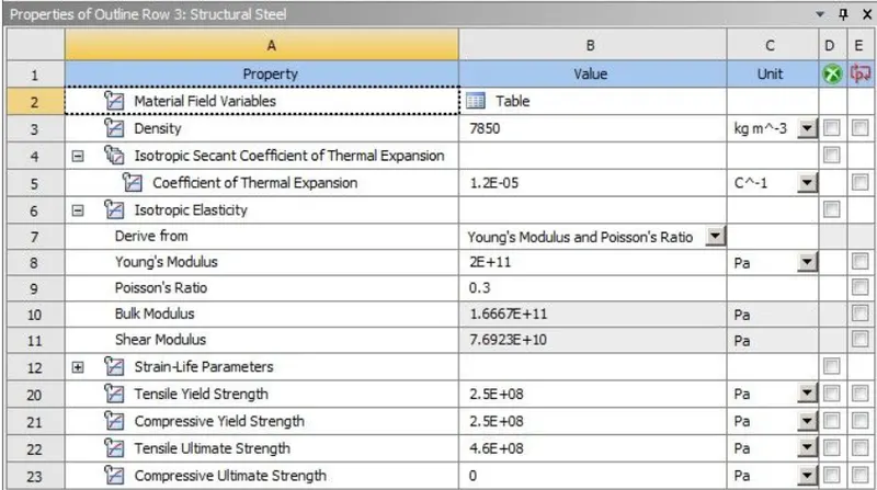
Fig.2.2 Material property details of worm gear assembly.
The material assigned for the worm gear assembly is structural steel.
2.3 Connection Details:
2.3.1 Contact details:
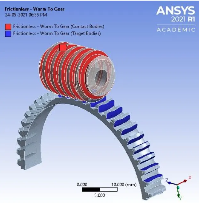
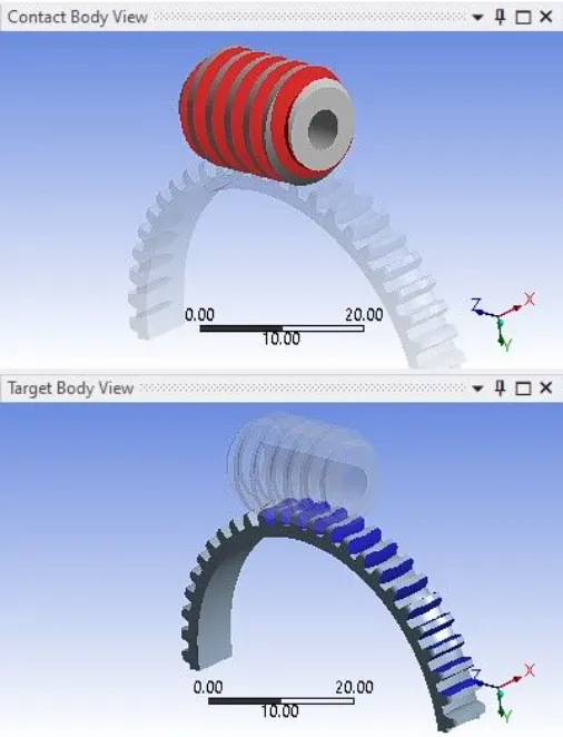
Fig.2.3.1 Contact details of worm and gear assembly.
The contact between, worm (contact body) and worm wheel (target body) are assigned as frictionless contact.
2.3.2 Joint Details:
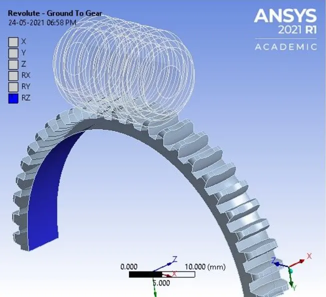
a. Revolute joint specified for worm wheel.
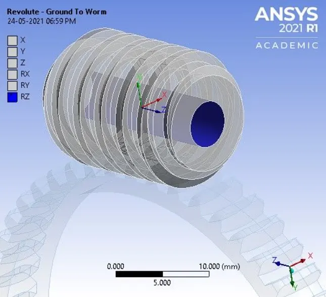
b. Revolute joint specified for worm.
Fig.2.3.2 Joint details of worm gear assembly,
In order to rotate the worm, the revolute type of joint is specified along -axis with connection type being body ground. The worm wheel is specified with revolute joint along -axis with connection type being body-ground to follow the rotary motion of the worm.
2.4 Meshing
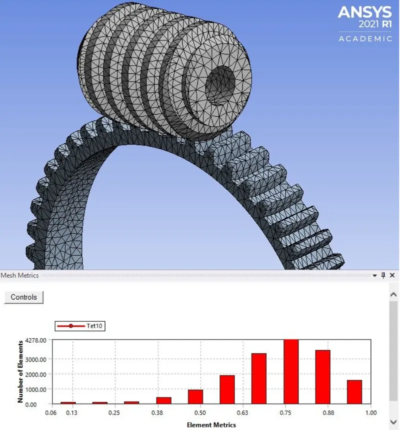
Fig.2.4 Meshing details of worm and gear assembly.
The element size of worm and gear assembly is set to 1 mm. The total number of nodes and elements generated are 29819 and 16018 respectively.
Note: The academic version of software has the problem size limit of 128k nodes or elements.
2.5 Boundary Conditions:
2.5.1 Analysis Settings:
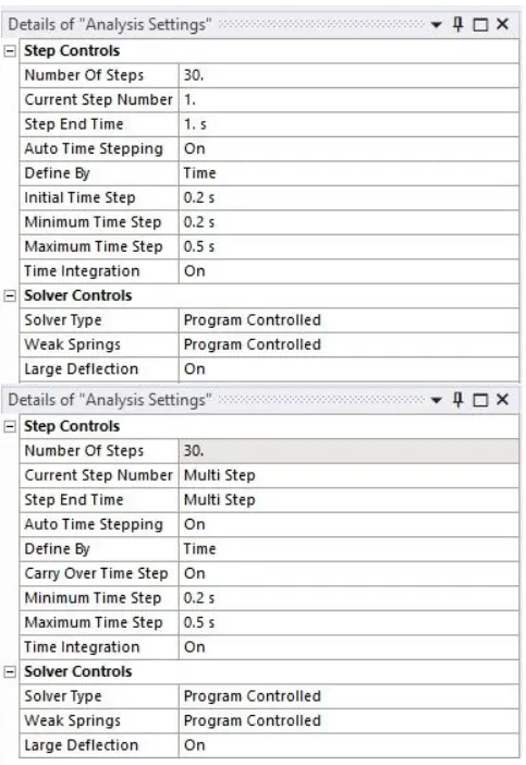
a. Analysis setting for step 1.
b. Analysis setting for step 2 to step 30.
Fig.2.5.1 Analysis settings.
In the analysis settings the number of steps considered is 30 and auto time stepping is set to 'On' which is defined by time'. For step 1, the initial, minimum and maximum time step is considered as 0.2s, 0.2s and 0.5s respectively. For step 2 to step 30, the minimum and maximum time step is 0.2s and 0.5s respectively. In the solver controls, solver type is chosen as 'Program controlled', weak springs is set to 'Program controlled' and large deflection is set to 'On'. Under the output controls, all the required results are set to 'Yes'.
2.5.2 Boundary condition:
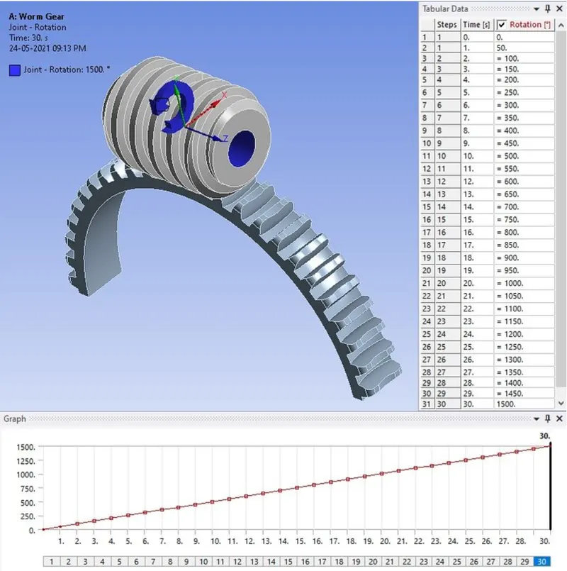
Fig.2.5.2 Joint load applied to worm.
The joint load is applied to worm to rotate it from 0° to 1500° with an increment of 50° in each step.
3. RESULTS AND DISCUSSIONS
3.1 Total Deformation.
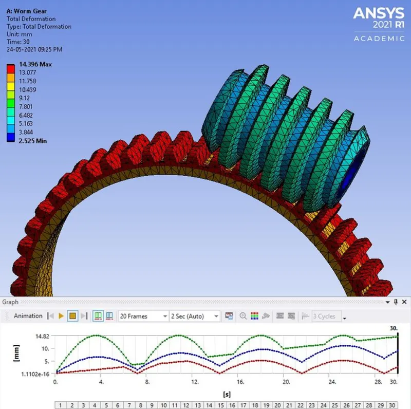
The maximum value of total deformation occurred during the simulation of worm gear is 14.396 mm.
3.2 Equivalent (v-m) Stress.
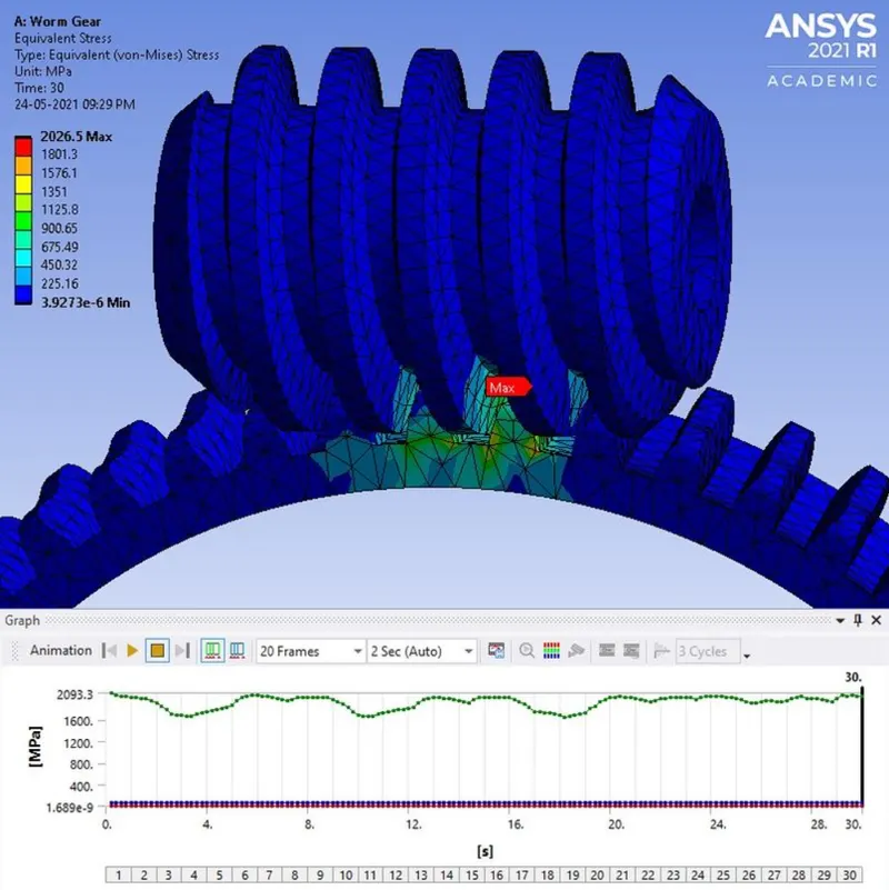
The maximum value of v-m stress is developed in the teeth of the worm wheel i.e. 2026.5 MPa which is more than
the yield stress value of the material i.e., 250 MP. Hence the teeth of the worm wheel will fail eventually during the service condition.
3.3 Equivalent Elastic Strain.
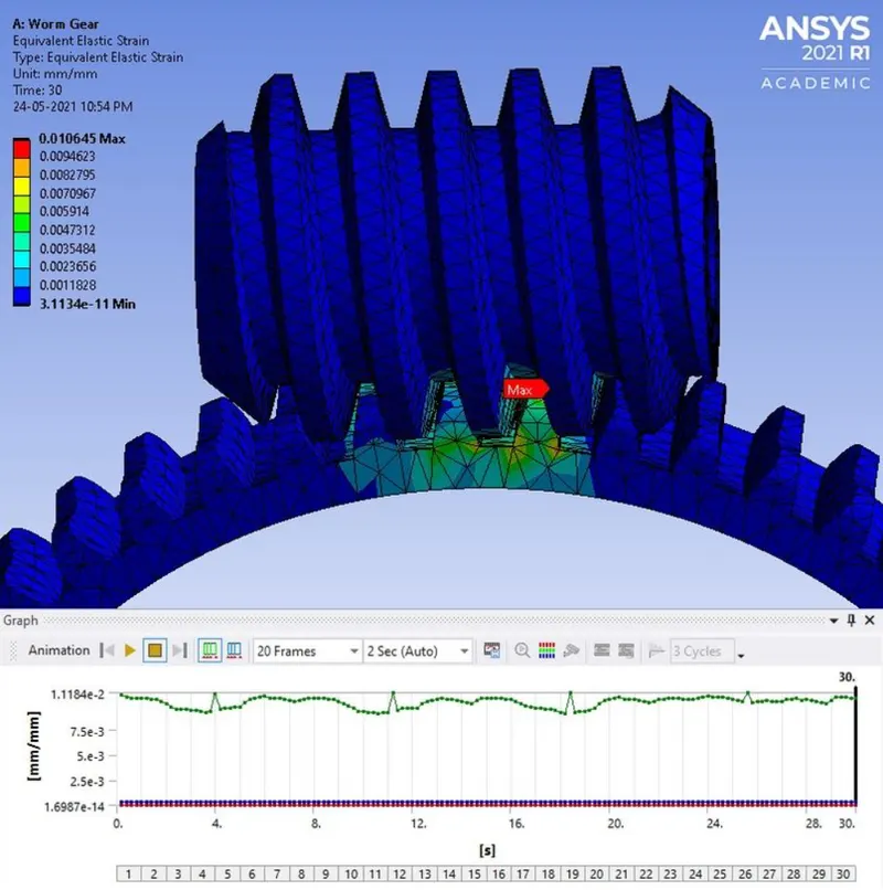
The maximum value of equivalent elastic strain is developed in the teeth of the worm wheel i.e., 0.010645.
3.4 Tabulation of Results:

CONCLUSION:
1. The transient structural analysis on a worm gear assembly was carried out successfully.
2. The maximum value of total deformation is 14.396 mm.
3. The maximum value of equivalent stress is developed in the teeth of the worm wheel i.e., 2026.5 MPa.
4. The maximum value of Equivalent Elastic Strain is developed in the teeth of the worm wheel i.e. 0.010645.
5. The maximum equivalent stress and strain is developed in the teeth of the worm wheel, which will eventually lead to failure hence, it is recommended to change the material of the teeth of worm wheel.