Week 8 Worm Gear Challenge
Aim:
The objective of this project is to run a worm gear simulation in Ansys.
Model Setup:
A CAD model was imported into Ansys transient structural workbench. The gear was cut into half to make it feasible to analyse in academic version.
Connections:
Contacts: Frictionless contact was defined between the inner surfaces of worm and gear as shown in image 1.
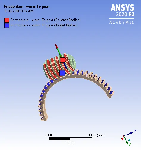
Image 1: Contact
Joints: Two revolute joints were defined as shown in image 2.
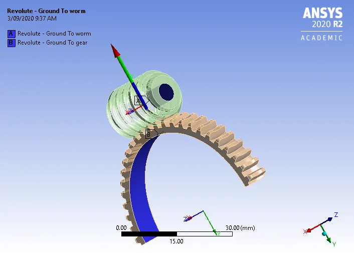
Image 2: Joint definitions
Mesh: A mesh size of 1.4mm was applied to both the bodies and resulted in 17944 nodes and 9359 elements as shown in image 3.
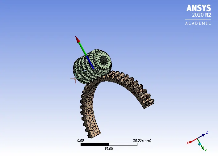
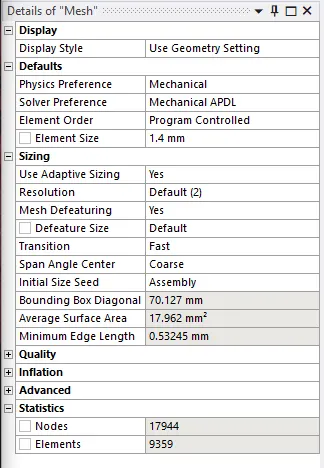
Image 3: Mesh Details
Analysis settings:
The analysis was set for 50 steps with a maximum time step of 0.5 seconds and a minimum time step of 0.2 seconds. The large deflections are On and weak springs are program-controlled. The joint was given a rotation of for each step as shown in image 4.
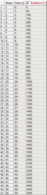
Image 4: Joint rotation table
Results and Conclusion:
The results are given in the table below:
| Total Deformation (mm) | Equivalent Stress (MPa) | Equivalent Elastic Strain | |
|
Maximum Minimum |
23.467 0.87692 |
1417.2 2.7657e-7 |
0.0072403 1.8027e-12 |
The images for the results of worm gear simulation are given in the below images:
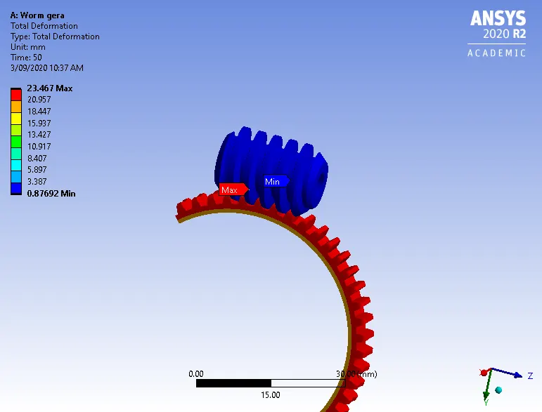
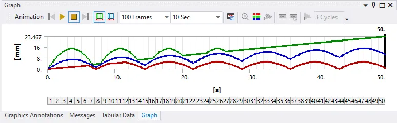
Image 5: Deformation in worm gear
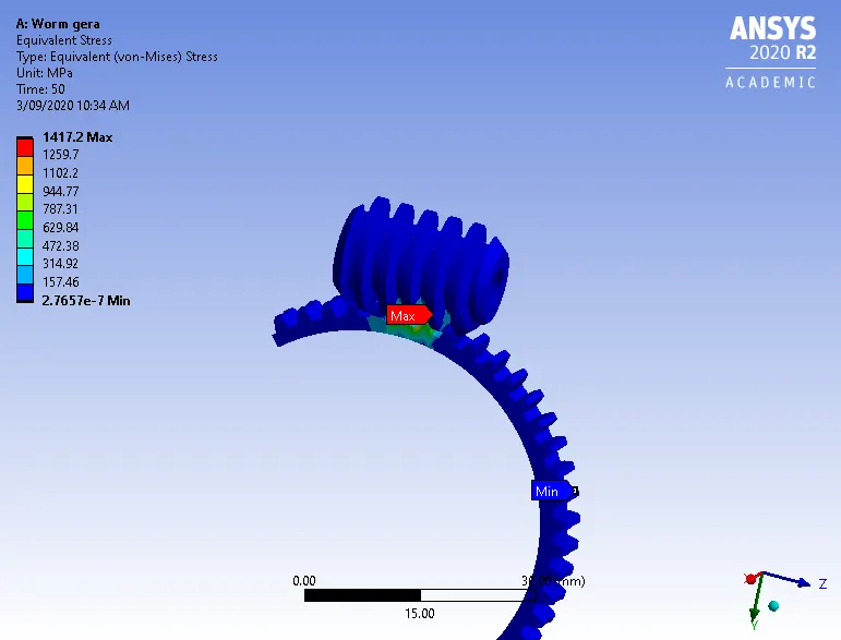
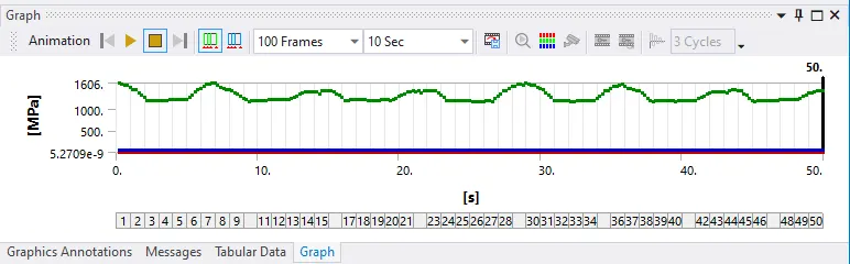
Image 6: Stress graph
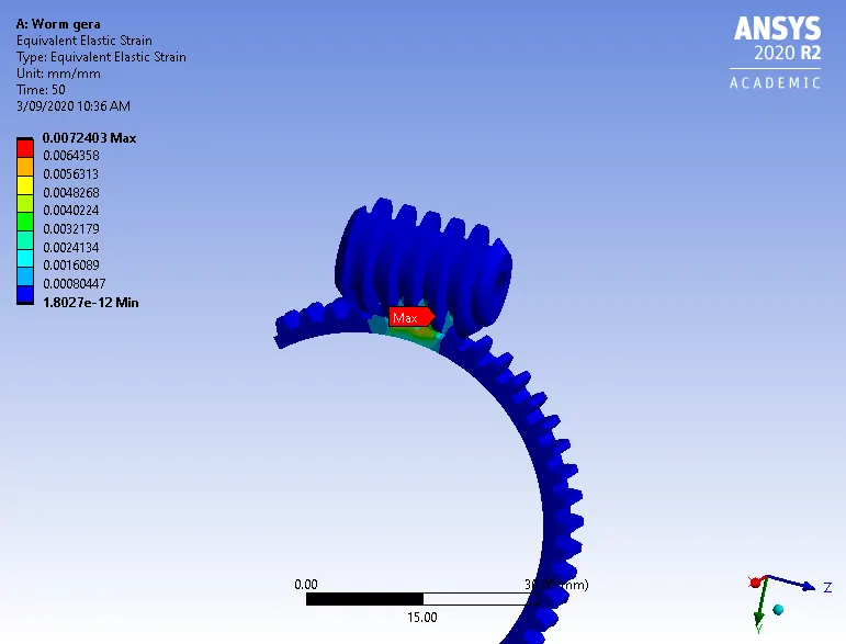
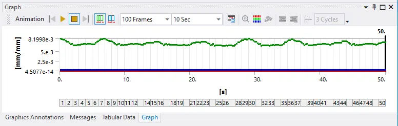
Image 7: Strain graph