Week 8 - Universal Joint
Stress Concentration on Double Universal Joint
OBJECTIVES:
To carry out a Static Structural Analysis on Double Universal Joint for the given three cases with Different Materials respectively and determine the stress, deformation, and strain.
CASE-1 Structural Steel:
For Case 1, Static Structural Analysis was carried out with the given model. The material used for this analysis was Structural Steel, and the analysis was carried out using ANSYS Mechanical Enterprise. The model for case-1 was imported to ANSYS Workbench software and is shown in the figure below.
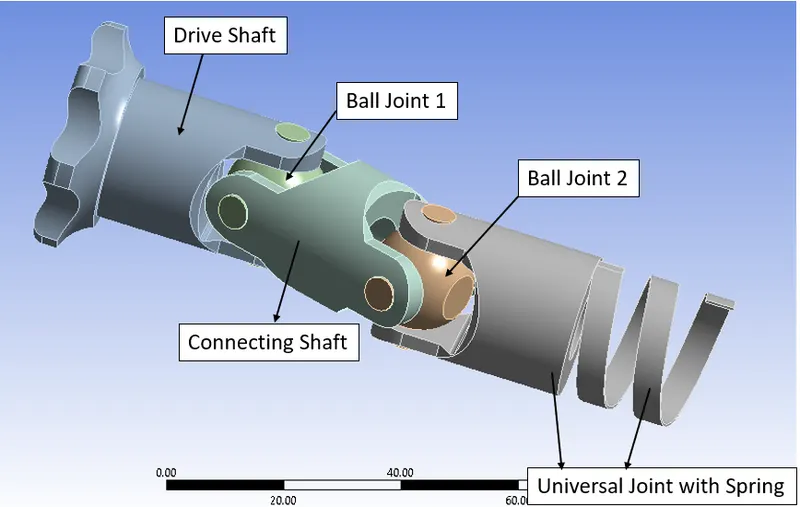
Fig.1 Double Universal Joint
Later the material was assigned and the material and its properties used for this analysis are specified below.
|
Material |
Structural Steel |
|
Density |
7.85e-6 kg/mm3 |
|
Young’s Modulus |
2e+5 MPa |
|
Thermal Conductivity |
0.06 W/mm°C |
|
Specific Heat |
4.34e+5 mJ/kg°C |
|
Yield Strength |
250 MPa |
|
Tensile Strength |
460 MPa |
|
Components |
All Components |
MESHING:
Meshing is done by setting an Element sizing of 4mm with Adaptive Sizing OFF and Smoothing Quality to LOW.
Fig.2 Element Quality
A mesh metric that identifies elements according to their quality was employed and it can be seen that the elements of the lowest quality are minimal. Most of the elements have very high quality in the range of 0.75 to 1. Hence, the mesh is of acceptable quality. The meshed model is shown below.
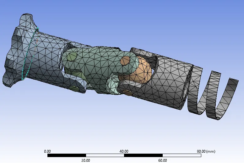
Fig.3 Meshed Model
JOINTS:
Eleven Joints were provided.
- FIXED Ground Joint: to Spring
- Revolute Ground Joint: to Drive Shaft
- Revolute Ground Joint: to Universal Joint
- Revolute Body Joint (8): Ball Joint 1 to Drive Shaft (4 joints), and Ball Joint 2 to Universal Joint (4 joints)
ANALYSIS SETTING:
5 STEPS ARE USED.
For all 5 steps:
- Auto Time Step: OFF
- Time Step: 0.1s
- Solver Type: Program Controlled
- Weak Spring: Program Controlled
- Large deflection: ON
- Output controls: Set all to YES
BOUNDARY CONDITIONS AND LOAD:
- Joint Load: Revolute – Ground to Component 1 (Drive Shaft)
- DOF: Rotation Z
- Type: Rotation
- Magnitude: Tabular Data
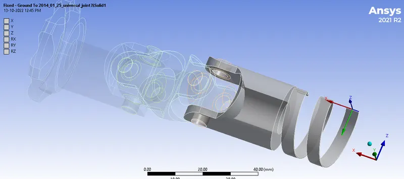
Fig.4 Fixed Joint
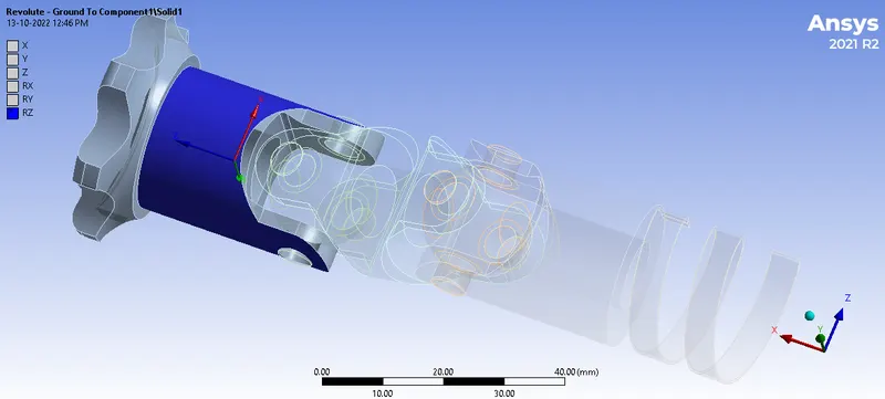
Fig.5 Revolute Ground Joint – Drive Shaft
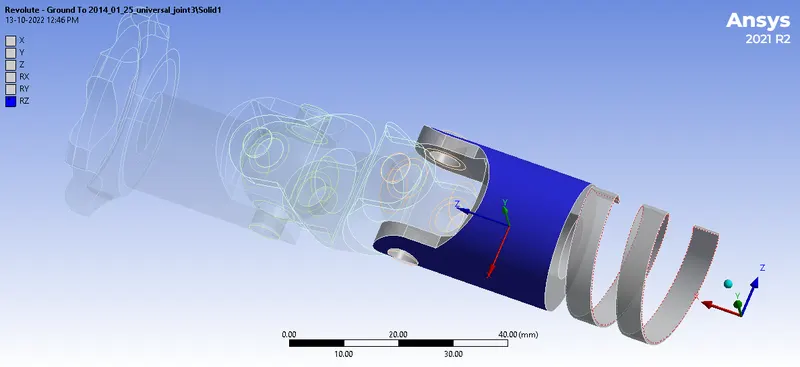
Fig.6 Revolute Ground Joint – Universal Joint
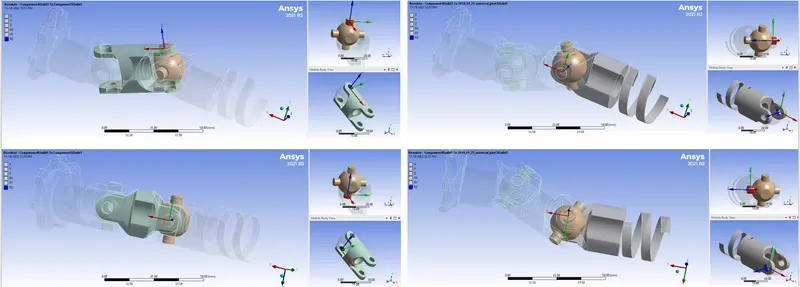
Fig.7 Revolute Body Joint – Ball Joint 1 to Drive Shaft (4)
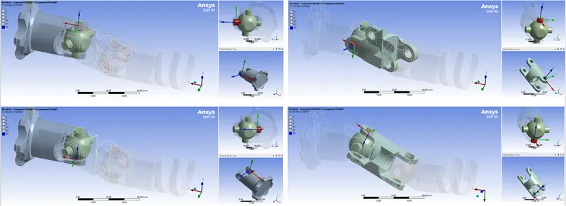
Fig.8 Revolute Body Joint – Ball Joint 2 to Universal Joint (4)
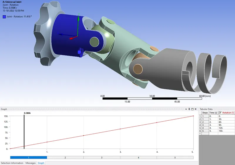
Fig.9 Revolute Joint Load
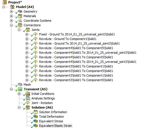
Fig.10 Case Setup
CASE-2 Stainless Steel:
For Case 2, Static Structural Analysis was carried out with the given model. The material used for this analysis was Stainless Steel, and Structural Steel and the analysis was carried out using ANSYS Mechanical Enterprise. The Material for case 2 is shown in the figure below.
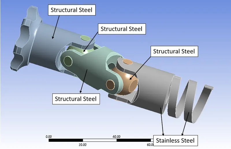
Fig.11 Materials Case-2
Later the material was assigned and the material and its properties used for this analysis are specified below. All other case setup remains same.
|
Material |
Structural Steel |
Stainless Steel |
|
Density |
7.85e-6 kg/mm3 |
7.75e-6 kg/mm3 |
|
Young’s Modulus |
2e+5 MPa |
1.93e+5 MPa |
|
Thermal Conductivity |
0.06 W/mm°C |
0.0151 W/mm°C |
|
Specific Heat |
4.34e+5 mJ/kg°C |
4.8e+5 mJ/kg°C |
|
Yield Strength |
250 MPa |
207 MPa |
|
Tensile Strength |
460 MPa |
586 MPa |
|
Components |
Other Components |
Universal Joint with Spring |
CASE-3 Frictional 0.2 COF:
For Case 2, Static Structural Analysis was carried out with the given model. The material used for this analysis was Titanium Alloy, and Structural Steel, and the analysis was carried out using ANSYS Mechanical Enterprise. The Material for case 3 is shown in the figure below.
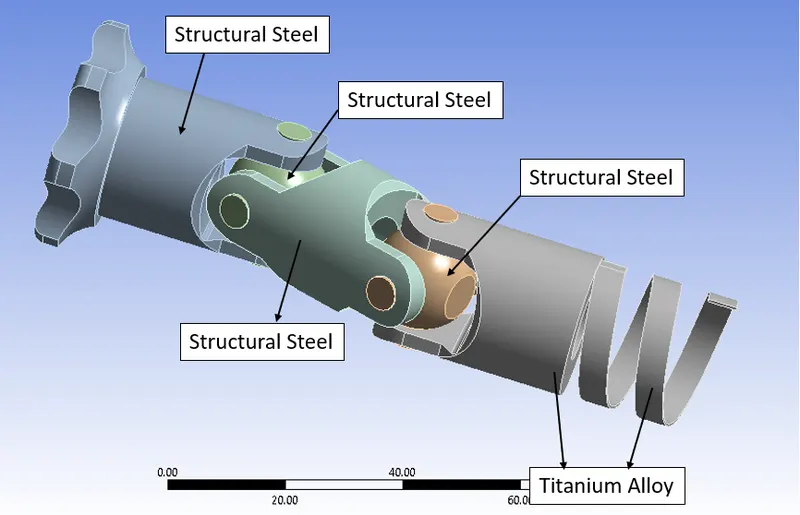
Fig.12 Materials Case-3
Later the material was assigned and the material and its properties used for this analysis are specified below. All other case setup remains same.
|
Material |
Structural Steel |
Titanium Alloy |
|
Density |
7.85e-6 kg/mm3 |
4.62e-6 kg/mm3 |
|
Young’s Modulus |
2e+5 MPa |
96000 MPa |
|
Thermal Conductivity |
0.06 W/mm°C |
0.0291 W/mm°C |
|
Specific Heat |
4.34e+5 mJ/kg°C |
5.22e+5 mJ/kg°C |
|
Yield Strength |
250 MPa |
930 MPa |
|
Tensile Strength |
460 MPa |
1070 MPa |
|
Components |
Other Components |
Universal Joint with Spring |
RESULTS:
The Total Deformation of the Setup obtained from the analysis is shown below.
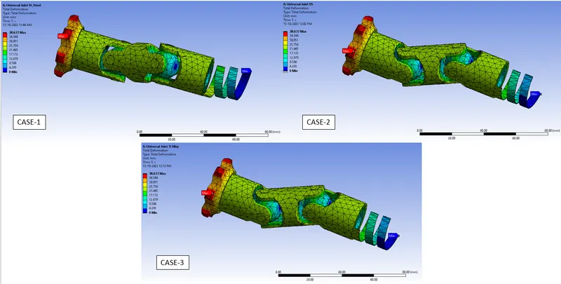
Fig.13 Total Deformation Contour Plot
The Equivalent (Von-Mises) Stress of the Setup obtained from the analysis is shown below.
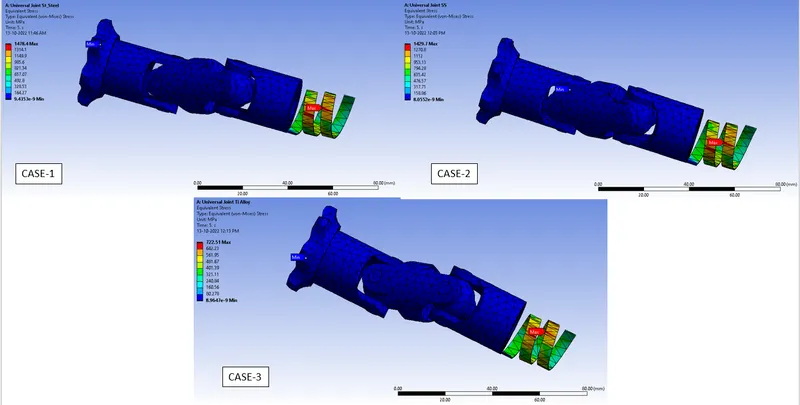
Fig.14 Equivalent Stress of Clip Contour Plot
The Equivalent Elastic Strain of the Setup obtained from the analysis is shown below.
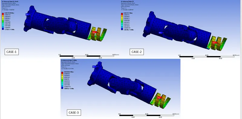
Fig.15 Equivalent Strain of the setup Contour Plot
The Total Deformation of the setup graph/table plot is shown below.
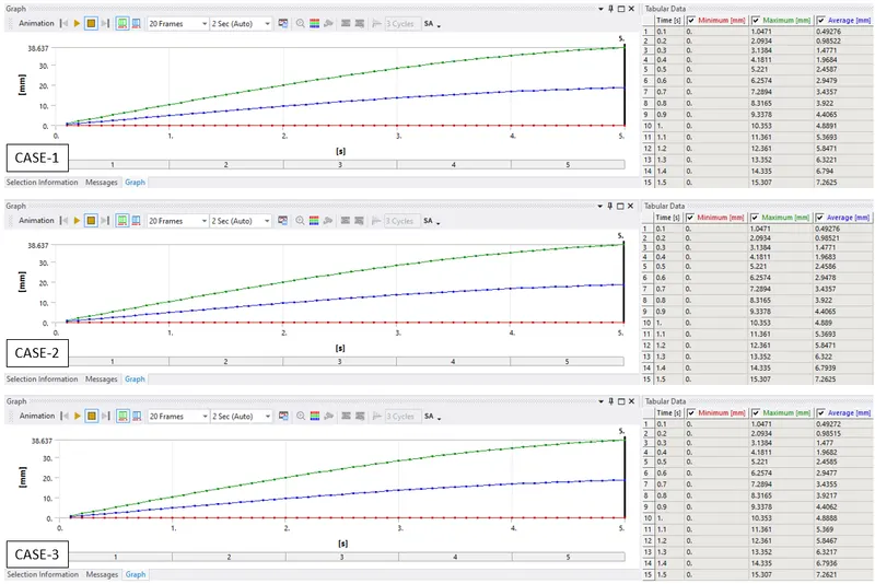
Fig.16 Total Deformation of the setup Table Plot
The Equivalent (Von-Mises) Stress of the Setup graph plot is shown below.
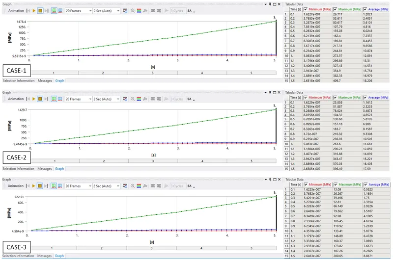
Fig.17 Equivalent Stress of the clip Table Plot
The Equivalent Strain of the Setup graph plot is shown below
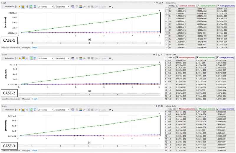
Fig.18 Equivalent Strain of the setup Table Plot
The analysis was carried out and the results are tabulated below.
|
Case |
Equivalent Stress Maximum [MPa] |
Equivalent Strain Maximum [mm/mm] |
Total Deformation Maximum [mm] |
|
1 (Structural Steel) |
1478.4 |
7.5618e-3 |
38.637 |
|
2 (Stainless Steel) |
1429.7 |
7.5770e-3 |
38.637 |
|
3 (Titanium Alloy) |
722.51 |
7.6931e-3 |
38.637 |
CONCLUSION:
The analysis was run successfully for all three cases and results were obtained and tabulated.
- Structural Steel has the Highest Stress.
- Titanium Alloy has the Lowest Stress.
- Total Deformation is the same in all three cases.
The order of Material for the Universal Joint with Spring is as follows:
Titanium Alloy >> Stainless Steel >> Structural Steel