Week 8 - Simulation of a backward facing step in OpenFOAM
DESCRIPTION:
To simulate an incompressible- laminar viscous flow through the backward facing step geometry.
The dimensions of the backward facing step geometry is given below.
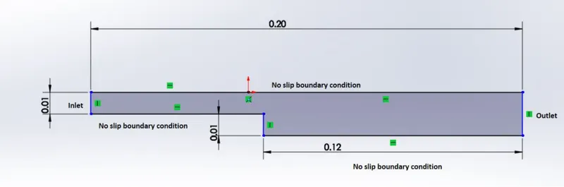
The back step is divided into 5 blocks as shown in the figure below

The mesh specifications are
200 among the x direction
20 among the y direction
CODE FOR CREATING THE BACK STEP GEOMETRY
for grading factor=1
we create the back step geometry by using gedit command and editting the blockMeshDict.
/*--------------------------------*- C++ -*----------------------------------*\
  =========                 |
  \\      /  F ield         | OpenFOAM: The Open Source CFD Toolbox
   \\    /   O peration     | Website:  https://openfoam.org
    \\  /    A nd           | Version:  8
     \\/     M anipulation  |
\*---------------------------------------------------------------------------*/
FoamFile
{
    version     2.0;
    format      ascii;
    class       dictionary;
    object      blockMeshDict;
}
// * * * * * * * * * * * * * * * * * * * * * * * * * * * * * * * * * * * * * //

convertToMeters 0.01;

vertices
(
    (0 0 0)//0
    (8 0 0)//1
    (8 0.5 0)//2
    (0 0.5 0)//3
    (8 1 0)//4
    (0 1 0)//5
    (20 1 0)//6
    (20 0.5 0)//7
    (20 0 0)//8
    (20 -1 0)//9
    (8 -1 0)//10
    (0 0 0.1)//11
    (8 0 0.1)//12
    (8 0.5 0.1)//13
    (0 0.5 0.1)//14
    (8 1 0.1) //15
    (0 1 0.1)//16
    (20 1 0.1)//17
    (20 0.5 0.1)//18
    (20 0 0.1)//19
    (20 -1 0.1)//20
    (8 -1 0.1)//21
);

blocks
(
    hex (0 1 2 3 11 12 13 14) (200 20 1) simpleGrading (1 1 1)//0
    hex (3 2 4 5 14 13 15 16) (200 20 1) simpleGrading (1 1 1)//1
    hex (1 8 7 2 12 19 18 13) (200 20 1) simpleGrading (1 1 1)//2
    hex (2 7 6 4 13 18 17 15) (200 20 1) simpleGrading (1 1 1)//3
    hex (10 9 8 1 21 20 19 12) (200 20 1) simpleGrading (1 1 1)//4
);

edges
(
);

boundary
(
    inlet
    {
        type wall;
        faces
        (
            (0 11 14 3)
            (3 14 16 5)
        );
    }
    outlet
    {
        type patch;
        faces
        (
          (8 7 18 19)
          (9 8 19 20)
          (7 6 17 18)
        );
    }
    walls
    {
        type wall;
        faces
        (
            (4 5 16 15)
            (6 4 15 17)
            (1 10 21 12)
            (0 1 12 11)
            (10 9 20 21)
        );
    }
);

mergePatchPairs
(
);

// ************************************************************************* //
In the blockMeshDict ,
- we initialise the vertices of the geomtery.
- after that we initialise the 5 blocks in the blocks function.
- We introduce the grading factor of 1.
- Then we seperate the faces of the blocks into the inlet,outlet and walls.
- save the file and exit the blockMeshDict.
Then we have to initialise the pressure and velocity conditions (p and U)
U:
/*--------------------------------*- C++ -*----------------------------------*\
  =========                 |
  \\      /  F ield         | OpenFOAM: The Open Source CFD Toolbox
   \\    /   O peration     | Website:  https://openfoam.org
    \\  /    A nd           | Version:  8
     \\/     M anipulation  |
\*---------------------------------------------------------------------------*/
FoamFile
{
    version     2.0;
    format      ascii;
    class       volVectorField;
    object      U;
}
// * * * * * * * * * * * * * * * * * * * * * * * * * * * * * * * * * * * * * //

dimensions      [0 1 -1 0 0 0 0];

internalField   uniform (1 0 0);

boundaryField
{
    inlet
    {
        type            fixedValue;
        value           uniform (3 0 0);
    }

    outlet
    {
        type            zeroGradient;
    }

    walls
    {
        type            slip;
    }
}

// ************************************************************************* //
In the velocity file (U) we
- We give the condition that the velocity of the fluid entering in the inlet is of fixed value of 3m/s.
- For the outlet we given the Zero Gradient(no velocity).
- Walls are given slip condition.
- Then we save the file and we exit.
p:
/*--------------------------------*- C++ -*----------------------------------*\
  =========                 |
  \\      /  F ield         | OpenFOAM: The Open Source CFD Toolbox
   \\    /   O peration     | Website:  https://openfoam.org
    \\  /    A nd           | Version:  8
     \\/     M anipulation  |
\*---------------------------------------------------------------------------*/
FoamFile
{
    version     2.0;
    format      ascii;
    class       volScalarField;
    object      p;
}
// * * * * * * * * * * * * * * * * * * * * * * * * * * * * * * * * * * * * * //

dimensions      [0 2 -2 0 0 0 0];

internalField   uniform 1;

boundaryField
{
    inlet
    {
        type            zeroGradient;
    }

    outlet
    {

        type            fixedValue;
        value           uniform 0;

    }


    walls
    {
        type            zeroGradient;
    }
}

// ************************************************************************* //
In the pressure file we
- We give the outlet condition that it is a fixed value of uniform pressure.
- We save the file and then we exit.
After the pressure and velocity conditions are initialised we head to the controlDict
controlDict:
/*--------------------------------*- C++ -*----------------------------------*\
  =========                 |
  \\      /  F ield         | OpenFOAM: The Open Source CFD Toolbox
   \\    /   O peration     | Website:  https://openfoam.org
    \\  /    A nd           | Version:  8
     \\/     M anipulation  |
\*---------------------------------------------------------------------------*/
FoamFile
{
    version     2.0;
    format      ascii;
    class       dictionary;
    location    "system";
    object      controlDict;
}
// * * * * * * * * * * * * * * * * * * * * * * * * * * * * * * * * * * * * * //

application     icoFoam;

startFrom       startTime;

startTime       0;

stopAt          endTime;

endTime         20;

deltaT          5e-4;

writeControl    timeStep;

writeInterval   10;

purgeWrite      0;

writeFormat     ascii;

writePrecision  6;

writeCompression off;

timeFormat      general;

timePrecision   6;

runTimeModifiable true;


// ************************************************************************* //
In the controlDict, we
- We initialise the start time at 0 seconds.
- We initialise the end time at 20 seconds
- The time difference (deltaT) will be initialised to 5e-4 for performing the computation accurately in every interval and also because the the core gets dumped for a larger value.
- We then save the file and then exit.
Now that all the necessary changes are made in the cavity file. We open the terminal and go inside the cavity file.
- We enter the blockMesh command.
- After that the block Mesh is obtained.
- Then we give the icoFoam command.
- Then the computations starts and begins to iterate.
- After computation,we give the paraFoam command.
- After this paraview is opened and the results are viewed.
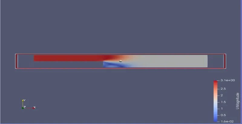
Velocity distribution:
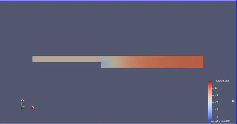
Pressure distribution:
velocity and pressure plot:
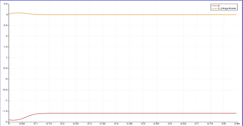
X axis represents the length along the y axis at a distance of 0.085 from the inlet.
Y axis represents the velocity in m/s
For a grading factor of 0.2:
We change the blockMeshDict code:

Rest of the procedures are the same as the above (GF=1)
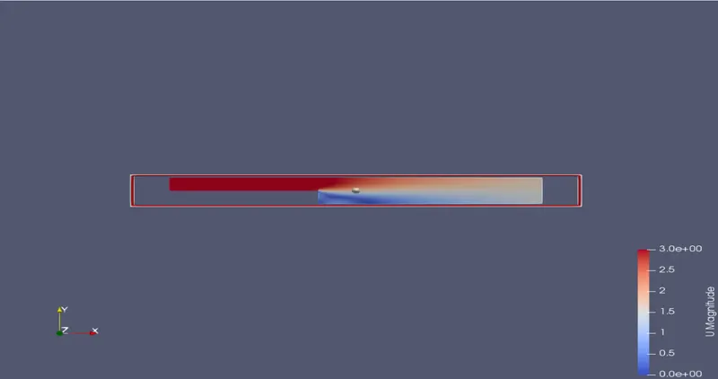
Velocity distribution:
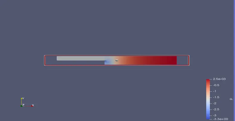
Pressure distribution:
velocity and pressure plot:
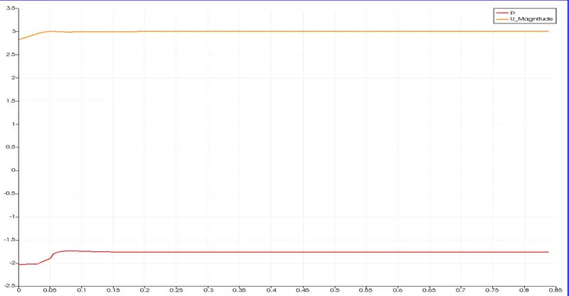
X axis represents the length along the y axis at a distance of 0.085 from the inlet.
Y axis represents the velocity in m/s
Result:
From the 2 plots we can conclude that the results have not varied for when we change the grading factor from 1 to 0.2 for getting the required mesh.This is because the mesh does not affect the flow ,velocity or pressure of the problem.Changing the grading factor of the mesh is done mainly to change the area of study (for accuracy) in the problem.For instance, a finer mesh in the boundary implies the pressure and velocity values or the simulation itself is more accurate in the boundary regions.
Grading Factor is essential for the process as we can increase or decrease the accuracy of the simulation to a certain geometry and also changes our focus to any particular point.