Week 8 - Simulation of a backward facing step in OpenFOAM
Aim of this challenge:
To set up transient simulations of an incompressible-laminar-viscous flow through the geomtery of a 'backward facing step' by choosing the most appropriate solver based on the physics of the problem with one set-up having a uniform mesh while the other having a 'grading factor' of '0.2' near the physical walls (including the wall of the step).
Description:
In this assignment, the task was to simulate an incompressible-laminar-viscous flow over the geometry of a ‘backward-facing step’.
Here, the preset 'tutorials' provided with OpenFOAM were modified to accommodate the specified problem.
The first task was obviously to find the right solver for this problem statement.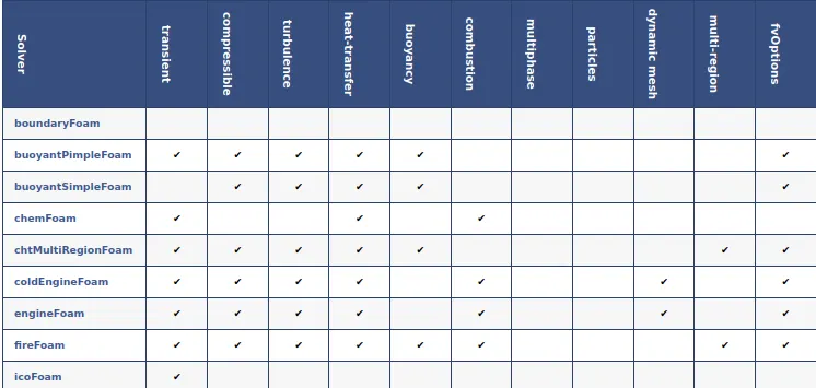
In the above capability matrix, it was seen that the “icoFOAM” solver was the best suited.
Locating the right Tutorial: The ‘directories’ in the tutorials are conveniently named after the corresponding solvers.
On opening the terminal, the “tut” shortcut was used to access the ‘tutorials’ directory.
On listing the objects in inside this directory, we find that the directory of interest was the ‘incompressible’ sub-directory.
It is in this directory that we find the tutorial corresponding to the ‘icoFOAM’ solver.
From the ‘icoFOAM’ directory, the ‘cavity’ directory was copied into the ‘run’ folder. This was to be our case-file. The modifications could be made and run here.
Geometry prep and Mesh generation:
It is required for the longer ‘x’ dimension to have 200 cells along its length and for the longer ‘y’ dimension to have 20.
From the freshly created directory in the ‘run’ folder, the ‘blockMeshDict’ script file was accessed by changing the present working directory to the ‘system’ sub-directory.
Here, the geometry was altered to suit the given problem.
For being able to conveniently create a finer mesh near the walls (using ‘simpleGrading’ to stretch the mesh that is away from the walls), we divided the geometry into five blocks.
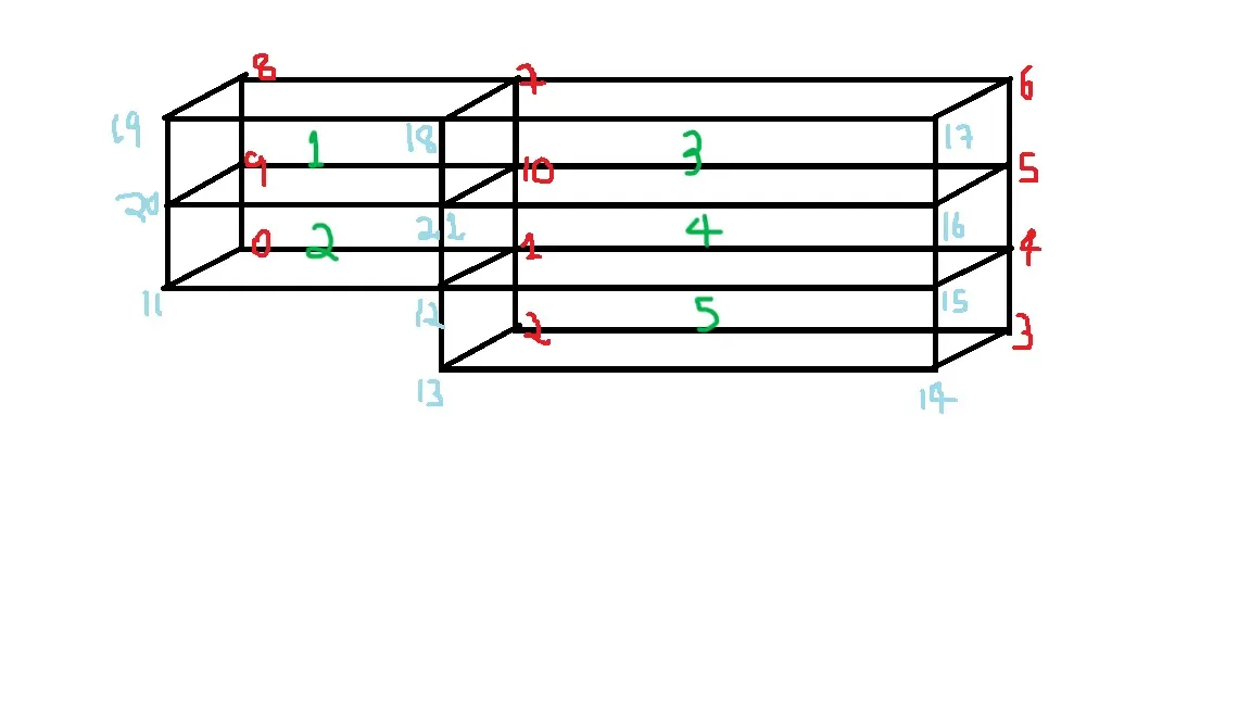
(Red vertices are on the backward face and the blue vertices on the forward face. The green markings label the blocks.)
This will enable the definition of the refined mesh needed in the second case.
The vertices are first defined in the ‘vertices’ section of the script file. As the code is in ‘C++’ the first vertex inputted (usually the origin) is given the index ‘0’. The indexing thus starts with ‘0’.
The blocks are then defined. The vertices for each block were entered in an order such that the local coordinate systems of the blocks were in tune with the global coordinate system. The ‘hex’ stands for the hexahedral type mesh that the blocks were to be meshed with. The grading factor for the first case was to be ‘1’ in all directions for all the blocks, thus creating a uniform mesh. The next section in the script file that was changed was the ‘boundaries’ section.
Here, the faces of the boundaries and their corresponding type were inputted in a manner such that when the vertices were taken in order, the thumb of the right hand pointed away from the geometry.
These changes were then saved. The “blockMesh” command was then run for mesh generation.
/*--------------------------------*- C++ -*----------------------------------*\
  =========                 |
  \\      /  F ield         | OpenFOAM: The Open Source CFD Toolbox
   \\    /   O peration     | Website:  https://openfoam.org
    \\  /    A nd           | Version:  9
     \\/     M anipulation  |
\*---------------------------------------------------------------------------*/
FoamFile
{
    format      ascii;
    class       dictionary;
    object      blockMeshDict;
}
// * * * * * * * * * * * * * * * * * * * * * * * * * * * * * * * * * * * * * //

convertToMeters 0.01;

vertices
(
    (0 0 0) //0
    (8 0 0) //1
    (8 -1 0) //2
    (20 -1 0) //3
    (20 0 0) //4
    (20 0.5 0) //5
    (20 1 0) //6
    (8 1 0) //7
    (0 1 0) //8
    (0 0.5 0) //9
    (8 0.5 0) //10
    (0 0 0.001) //11
    (8 0 0.001) //12
    (8 -1 0.001) //13
    (20 -1 0.001) //14
    (20 0 0.001) //15
    (20 0.5 0.001) //16
    (20 1 0.001) //17
    (8 1 0.001) //18
    (0 1 0.001) //19
    (0 0.5 0.001) //20
    (8 0.5 0.001) //21
);

blocks
(
    hex (9 10 7 8 20 21 18 19) (80 5 1) simpleGrading (1 1 1)
    hex (0 1 10 9 11 12 21 20) (80 5 1) simpleGrading (1 1 1)
    hex (10 5 6 7 21 16 17 18) (120 5 1) simpleGrading (1 1 1)
    hex (1 4 5 10 12 15 16 21) (120 5 1) simpleGrading (1 1 1)
    hex (2 3 4 1 13 14 15 12) (120 10 1) simpleGrading (1 1 1)
);

edges
(
);

boundary
(
    inlet
    {
        type wall;
        faces
        (
            (0 11 20 9)
            (9 20 19 8)
        );
    }
    outlet
    {
        type wall;
        faces
        (
            (14 3 4 15)
            (15 4 5 16)
            (16 5 6 17)
        );
    }
    frontAndBack
    {
        type empty;
        faces
        (
            (9 8 7 10)
            (0 9 10 1)
            (10 7 6 5)
            (1 10 5 4)
            (2 1 4 3)
            (11 12 21 20)
            (20 21 18 19)
            (13 14 15 12)
            (12 15 16 21)
            (21 16 17 18)
        );
    }
    fixedWalls
    {
    	type wall;
    	faces
    	(
    		(8 19 18 7)
    		(7 18 17 6)
    		(2 3 14 13)
    		(2 13 12 1)
    		(0 1 12 11)
    	);
    }
);

mergePatchPairs
(
);

// ************************************************************************* //
The dimension of the generated mesh cells was ‘0.001m’. To keep the courant number at an acceptable value, it was decided to set the inlet velocity as ‘0.8m/s’ and the time-step size as ‘0.001s’
Inputting the time-step size:
The next script file to be edited was the ‘controlDict’ where the decided value of the time-step was inputted. To ensure convergence, the simulation time was upped to 5 seconds.
/*--------------------------------*- C++ -*----------------------------------*\
  =========                 |
  \\      /  F ield         | OpenFOAM: The Open Source CFD Toolbox
   \\    /   O peration     | Website:  https://openfoam.org
    \\  /    A nd           | Version:  9
     \\/     M anipulation  |
\*---------------------------------------------------------------------------*/
FoamFile
{
    format      ascii;
    class       dictionary;
    location    "system";
    object      controlDict;
}
// * * * * * * * * * * * * * * * * * * * * * * * * * * * * * * * * * * * * * //

application     icoFoam;

startFrom       startTime;

startTime       0;

stopAt          endTime;

endTime         5;

deltaT          0.001;

writeControl    timeStep;

writeInterval   20;

purgeWrite      0;

writeFormat     ascii;

writePrecision  6;

writeCompression off;

timeFormat      general;

timePrecision   6;

runTimeModifiable true;


// ************************************************************************* //
Defining the initial conditions:
The ‘0’ directory in the case-file contains all the script-files defining the initial conditions.
Velocity (‘U’)
In the ‘boundaryField’ section, the ‘movingWall’ boundary was renamed to the ‘inlet’. The type remained as ‘fixedValue’ and was changed to 0.8m/s.
Below this, a sub-section for ‘outlet’ was also created and was given the type ‘zeroGradient’.
The remaining parts of this section, remaining as it is, suited the set-up.
/*--------------------------------*- C++ -*----------------------------------*\
  =========                 |
  \\      /  F ield         | OpenFOAM: The Open Source CFD Toolbox
   \\    /   O peration     | Website:  https://openfoam.org
    \\  /    A nd           | Version:  9
     \\/     M anipulation  |
\*---------------------------------------------------------------------------*/
FoamFile
{
    format      ascii;
    class       volVectorField;
    object      U;
}
// * * * * * * * * * * * * * * * * * * * * * * * * * * * * * * * * * * * * * //

dimensions      [0 1 -1 0 0 0 0];

internalField   uniform (0 0 0);

boundaryField
{
    inlet
    {
        type            fixedValue;
        value           uniform (0.8 0 0);
    }

    outlet
    {
        type            zeroGradient;
    }

    fixedWalls
    {
        type            noSlip;
    }

    frontAndBack
    {
        type            empty;
    }
}

// ************************************************************************* //
Kinematic Pressure (‘p’)
For, pressure and velocity conditions, if one is specified as a Neumann B.C, then the other must take on a Dirichlet B.C and vice-versa.
Similar changes to the script file were made as in the case for velocity.
In the ‘boundaryFields’, the ‘movingWall’ was similarly renamed and repurposed for defining the ‘inlet’. The type remained as ‘zeroGradient’, a Neumann B.C as the velocity B.C for here was subjected to a Dirichlet B.C. Similarly, for the outlet (for which a new sub-section was created), a ‘fixedValue’ of ‘uniform 0’ was inputted (being a Dirichlet condition).
For the ‘fixedWalls’, the type was inputted as ‘zeroGradient’ (a Neumann condition as the no slip condition was imposed for the velocity B.C here).
The ‘frontAndBack’ were given the type ‘empty’ as usual.
/*--------------------------------*- C++ -*----------------------------------*\
  =========                 |
  \\      /  F ield         | OpenFOAM: The Open Source CFD Toolbox
   \\    /   O peration     | Website:  https://openfoam.org
    \\  /    A nd           | Version:  9
     \\/     M anipulation  |
\*---------------------------------------------------------------------------*/
FoamFile
{
    format      ascii;
    class       volScalarField;
    object      p;
}
// * * * * * * * * * * * * * * * * * * * * * * * * * * * * * * * * * * * * * //

dimensions      [0 2 -2 0 0 0 0];

internalField   uniform 0;

boundaryField
{
    inlet
    {
        type            zeroGradient;
    }

    outlet
    {
        type            fixedValue;
        value		uniform 0;
    }

    fixedWalls
    {
        type            zeroGradient;
    }

    frontAndBack
    {
        type            empty;
    }
}

// ************************************************************************* //
After making these changes, we run the simulation by typing ‘icoFoam’ into the terminal with the present working directory as the copied tutorial directory.
For case 2:
The grading factor is defined as the ratio of the cell dimension of the last cell in the specified direction to that of the first.
The only changes are made to the ‘blockMeshDict’.
/*--------------------------------*- C++ -*----------------------------------*\
  =========                 |
  \\      /  F ield         | OpenFOAM: The Open Source CFD Toolbox
   \\    /   O peration     | Website:  https://openfoam.org
    \\  /    A nd           | Version:  9
     \\/     M anipulation  |
\*---------------------------------------------------------------------------*/
FoamFile
{
    format      ascii;
    class       dictionary;
    object      blockMeshDict;
}
// * * * * * * * * * * * * * * * * * * * * * * * * * * * * * * * * * * * * * //

convertToMeters 0.01;

vertices
(
    (0 0 0) //0
    (8 0 0) //1
    (8 -1 0) //2
    (20 -1 0) //3
    (20 0 0) //4
    (20 0.5 0) //5
    (20 1 0) //6
    (8 1 0) //7
    (0 1 0) //8
    (0 0.5 0) //9
    (8 0.5 0) //10
    (0 0 0.001) //11
    (8 0 0.001) //12
    (8 -1 0.001) //13
    (20 -1 0.001) //14
    (20 0 0.001) //15
    (20 0.5 0.001) //16
    (20 1 0.001) //17
    (8 1 0.001) //18
    (0 1 0.001) //19
    (0 0.5 0.001) //20
    (8 0.5 0.001) //21
);

blocks
(
    hex (9 10 7 8 20 21 18 19) (80 5 1) simpleGrading (0.2 0.2 1)
    hex (0 1 10 9 11 12 21 20) (80 5 1) simpleGrading (0.2 5 1)
    hex (10 5 6 7 21 16 17 18) (120 5 1) simpleGrading (5 0.2 1)
    hex (1 4 5 10 12 15 16 21) (120 5 1) simpleGrading (5 5 1)
    hex (2 3 4 1 13 14 15 12) (120 10 1) simpleGrading (5 5 1)
);

edges
(
);

boundary
(
    inlet
    {
        type wall;
        faces
        (
            (0 11 20 9)
            (9 20 19 8)
        );
    }
    outlet
    {
        type wall;
        faces
        (
            (14 3 4 15)
            (15 4 5 16)
            (16 5 6 17)
        );
    }
    frontAndBack
    {
        type empty;
        faces
        (
            (9 8 7 10)
            (0 9 10 1)
            (10 7 6 5)
            (1 10 5 4)
            (2 1 4 3)
            (11 12 21 20)
            (20 21 18 19)
            (13 14 15 12)
            (12 15 16 21)
            (21 16 17 18)
        );
    }
    fixedWalls
    {
    	type wall;
    	faces
    	(
    		(8 19 18 7)
    		(7 18 17 6)
    		(2 3 14 13)
    		(2 13 12 1)
    		(0 1 12 11)
    	);
    }
);

mergePatchPairs
(
);

// ************************************************************************* //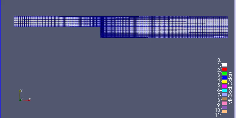
The grading factors were inputted such that the mesh was finer closer to the physical walls.
This ensured that the maximum physics were captured in these regions of importance without expending too much of the available computational resource.
Why is ‘Grading Factor’ important in meshing?
The grading factor is the ratio of the cell dimension of the last cell in a specified dimension to that of the first cell.
Thus, it ‘stretches’ the mesh in the way we require it, coarser towards a direction and finer in the direction opposite towards it and vice-versa.
Thus, this ‘stretching’ of the mesh lets us keep the mesh finer in places of interest (like near the walls in this problem) while keeping the total number of computational cells as low as possible. Thus, it lets us capture more accurate results without taking on too much of the added computational cost.
Thus, in short, such an altered mesh give more accurate results while being computationally efficient.
Post-processed results:
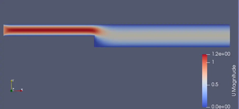
(Contour for velocity magnitude in the flow domain.)
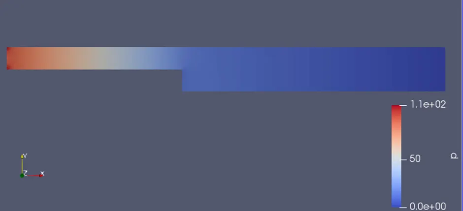
(Contour for kinematic pressure in the flow domain.)
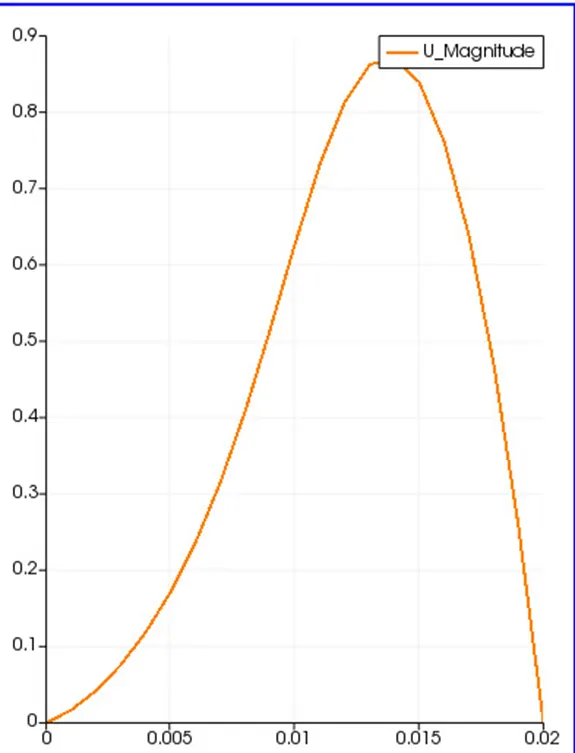
(Line plot for velocity magnitude at 0.085m from the inlet)
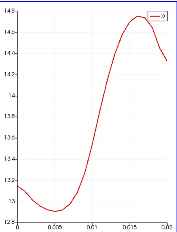
(Line plot for velocity magnitude at 0.085m from the inlet)
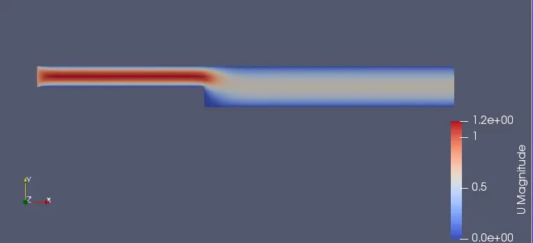
(Contour for velocity magnitude in the flow domain.)
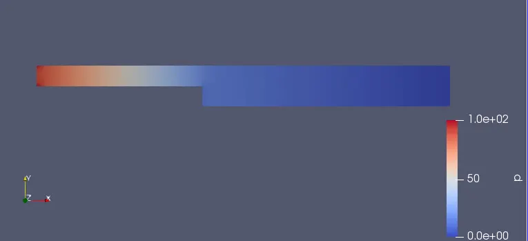
(Contour for kinematic pressure in the flow domain.)
For case 2:
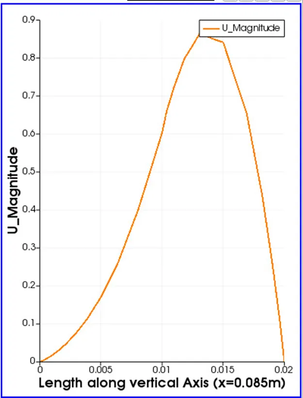
(Line plot for velocity magnitude at 0.085m from the inlet)
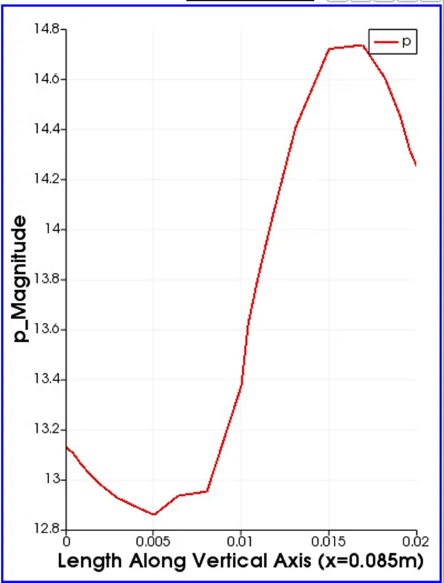
(Line plot for velocity magnitude at 0.085m from the inlet)
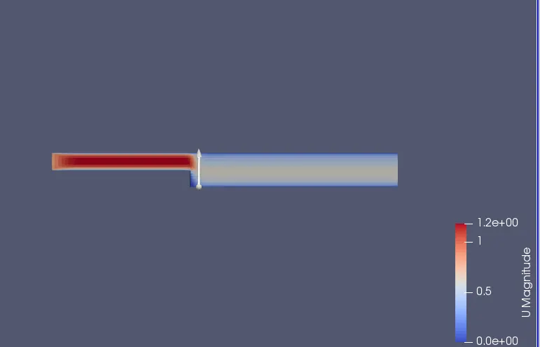
(Contour for velocity magnitude in the flow domain.)
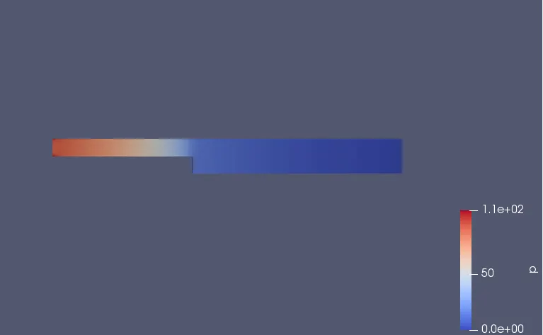
(Contour for kinematic pressure in the flow domain.)