Week 3 Challenge : CFD meshing on Turbocharger
AIM: To check the supplied model for geometric errors, performing topological corrections to make it suitable for surface and volume meshing.
Procedure: Single cons were trickier to solve In comparison to the previous challenges.
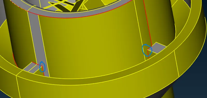
Here, we cannot create a new face in one step. Using the ‘Multi Project’ tool, the hot points on the corners of the rectangular structures (shown in the pictures with the blue circles) were projected onto to the CONS directly above it. Then new rectangular faces were created over these structures with the help of these hot points. After this, the remaining part was simply closed off with the ‘Fill Hole’ option.
The next single cons to solve was due to a jutting surface in the interior.
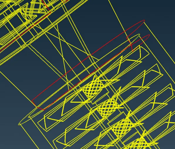
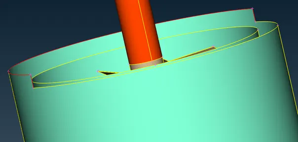
Here, I projected the cons using the ‘Project’ cons in the CONS group to project the cons of the inner surface onto the outer face. Thus, the jutting surface could now be conveniently selected and deleted. This was a better method than using the ‘Intersect’ option as shown in the video.
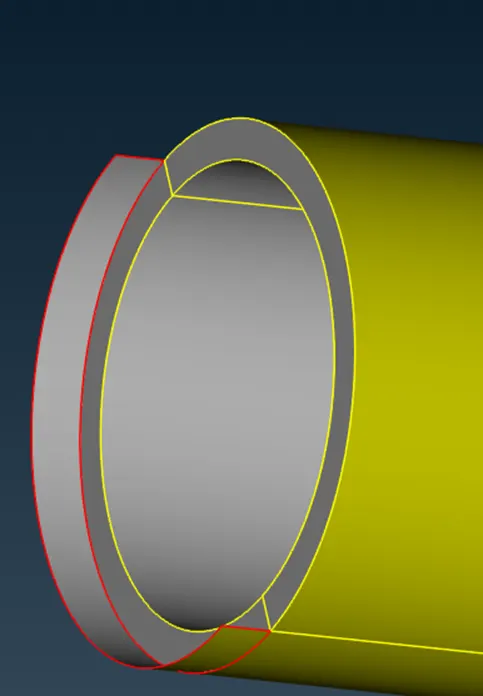
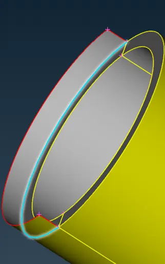
A similar method was used here to project the cons onto outer most surface and thus creating a triple con. The jutting surface was then deleted and the triple cons was turned into a double cons.
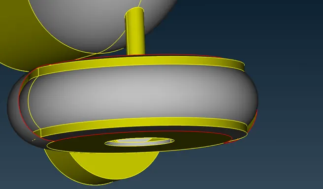
This face was created in parts. 14 hot points were symmetrically inserted (7 on each cons) on both the cons on the side of the opening. This was done by using the ‘Parametric’ option. Hot points were inserted in the mid points (putting 0.5 as the parameter). This method also ensured that a smooth surface was created.
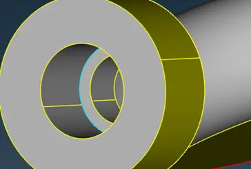
This triple ‘cons’ is a required one as it is the meeting point of three undeletable surfaces.
Now, I switched my view to PID view and saw that the inlet casing had overlapping surfaces. Using ‘PID Region’ I selected the pink PID region and deleted it.
There were several more overlapping surfaces on the ‘Rotor Shaft’. The common method was to project the cons onto the overlapping face and then deleting the separated surfaces. The ‘Fine’ tool was used in each case in the ‘Auxiliaries’ group. Here are examples:
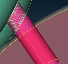
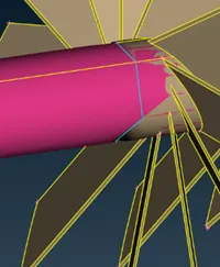
Now, I had to solve the triple cons in the shaft and make the shaft, the blades and the impeller to be a continuous volume. So, the faces separating these were deleted. To do this for the impeller, the cons of the shaft was projected onto the face of the impeller. The separated face was then deleted.
I hid both ends of the rotor assembly to confirm if it was a single continuous volume. This was done using the ‘NOT’ option. As I could see through to the ANSA window, I concluded that it was a continuous hollow surface.
The model was closed off using the fill hole option (to close off the inlet/outlet holes in the compressor casing and the hole in the turbo casing).
Then, the PIDs were assigned using the PID manager. Separate PIDs were assigned to the Inlet/outlet of the casing.
Then the surface meshing was performed.
The meshing was done by selecting the PIDs with separate target lengths.
The turbo and the compressor were meshed. The quality criteria were fed accordingly. The mesh type was chosen to be 5mm, the minimum and the maximum lengths were 3mm and 7mm.
Then from the perimeters section, the ‘Length’ option was chosen and the 5mm length was inputted for both the ‘Macros’ and the ‘Perimeter’ sections.
Then using ‘Spot Mesh”, the visible model was meshed. The rotor shaft and the blade stages were similarly meshed with 1mm target length (0.5mm being the minimum length and 2mm being the maximum length).
Similarly, this was done for the impeller. But the mesh for the region in the shaft in contact with the impeller was erased. This was because of different target lengths of meshing coming together at a single boundary. So, the ‘Lengths’ option was used again to see for the ranges of lengths in both the perimeters and the macros section in the concerned location. Once seeing that range accommodated the target lengths of both the meshes, the region was re meshed using the ‘Spot Mesh’ algorithm (target length=1mm, min length=0.5mm and max length=2mm).
Similarly, macros of the turbo and compressor casing that were in contact were facing similar issues. The same process was followed and those surfaces were re meshed with their appropriate quality criteria (5mm target length, 3mm min length and 7mm max length).
Then in the meshing tab, from the macros group, the cut option was selected. The heal cut option was checked, mesh mode was changed to flexible and in the options drop down, the ‘Parametric’ cut was chosen. Then cuts were made around the region where the shaft was meeting the macros on the casings to ease the transitions towards the shaft.
Then it was time for volumetric meshings.
In the volumes tab, the define option was chosen. The list only showed 7 detected volumes. On further investigation, there were openings that were missed in the compressor casing. They were patched using the ‘COONS” options and the surfaces in contact with those opening had to be re meshed.
This time ANSA auto detected all 8 volumes. The volumes corresponding to the parent geometry of the structures were deleted.
The remaining had to be meshed with “Tetra Rapid” volumetric meshes.
All the volumes were meshed except the turbo casing. An error warned me of an “OPEN VOLUME”. I checked for topological errors first. Since there were none, it was obviously the surface meshing that was causing issues. I sought help.
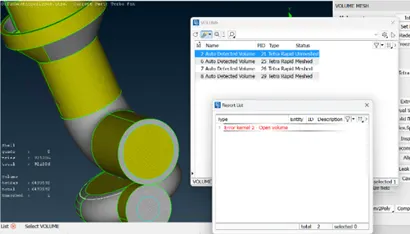
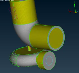
I was advised to go to the ‘Spacing’ option in the perimeters group and to change the minimum and maximum lengths to 0.3mm and 5mm.
After remeshing with these changed criteria, I was able to finish the volumetric meshing.
LEARNING OUTCOMES: I was advised in the future to mesh the components with smaller target lengths first and then to freeze them so that the remaining components can be meshed. This would prevent the sort of errors that prevented me from completing the volumetric meshing on the turbo casing.
This was an important take-away.
CONCLUSION: I was introduced to volumetric meshings and learned of the complications that could arise from meshing the different PIDs/Components with different target lengths.