Project 1 : CFD Meshing for Tesla Cyber Truck
AIM: To perform Topological cleanup on the given model of a Cybertruck and to correct geometrical errors and then surface. The cleaned-up model is then surface meshed with appropriate quality criteria and target lengths. The meshed model is then enclosed in a wind tunnel. The wind tunnel is then surface meshed. The volume between the truck and the enclosing tunnel is to be meshed with tetra rapid volumetric mesh.
Procedure:
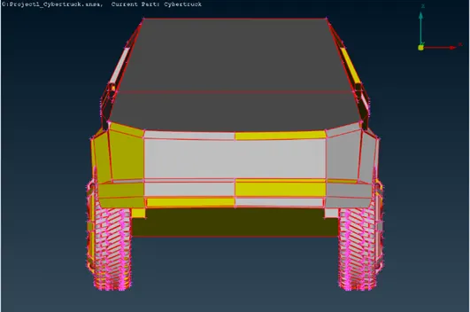
(The received model.)
The ‘length’ option in the perimeters group was used after selecting all the perimeters of the model (via box selection). The length was set to 1mm (for better resolution).
The ‘Topo’ option was used after selecting the whole model via box selection. This solved for most of the single cons.
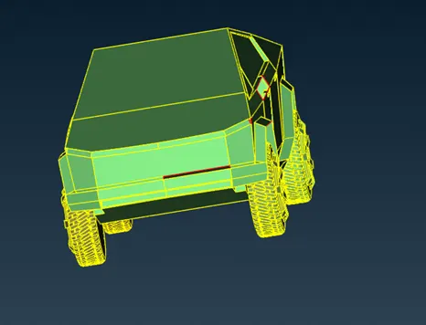
The gaps were filled using the “Fill Hole” option or using the “New” options in the ‘Faces’ tab (using either the ‘Fitted’ or the ‘Coons’ algorithms).
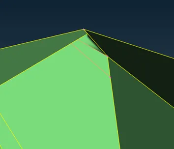
The sharp edges were fixed by deleting some surfaces and creating new ones using the ‘New’ ones. The extra cuts were then deleted. The truck had many such sharp angles. These could have caused issues while meshing as this may cause many elements to fail the skewness criteria.
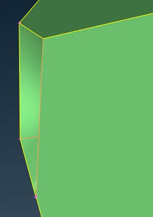
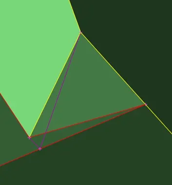
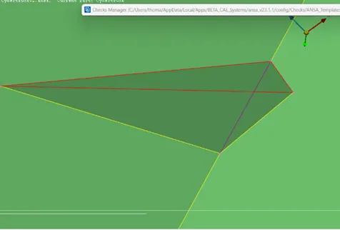
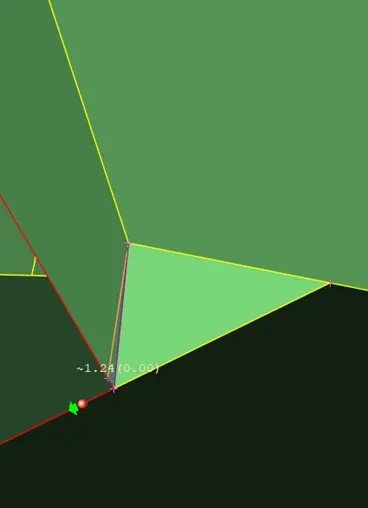
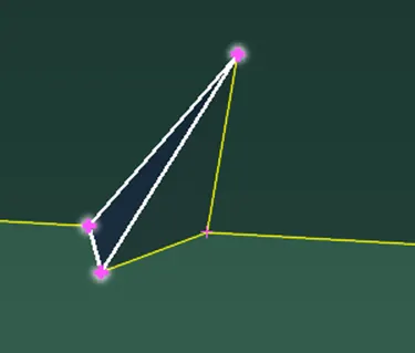
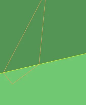
There were also many ‘Cracks between Cons’:
They were fixed by creating new ‘Curves’ (see in picture). Then a new face was created along these contours. The surfaces inside were deleted to remove the triple cons formed.

The inside of the model was also cleaned up. The door handles were patched up after deleting thew surfaces inside.
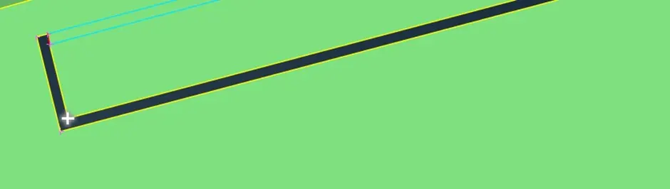
The cuts demarcating the handles were then deleted.
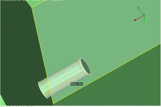
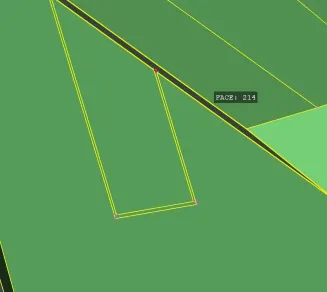
similar treatment was given to these “motors” and the “charging ports”. This cleaned up the inside of truck.
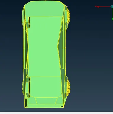
I anticipated that these sharp features may cause issues while meshing.
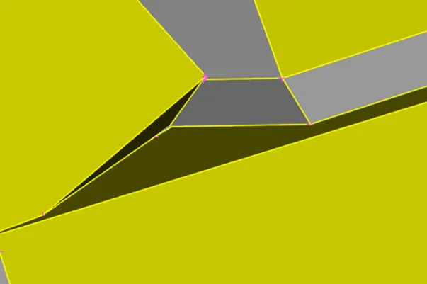
So, this area near the front of the car was patched into this:
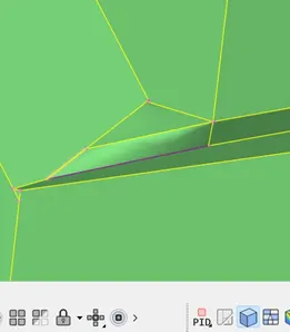
<!--[endif]-->
The topo cleanup was more labourious than expected. Cuts were made across the model to halve it. One half of the model was deleted and the remainig was worked on. After topo cleanup and meshing, the 'Symmetry' option in the transfrom gruop was used to mirror the other half using a three point symmetry plane.

I anticipated that the skewed geometry of the window panes might cause issues while meshing. So ,this area was fixed up by creating a new face to cover this skewed geometry and the surfaces inside were deleted. (refer pictures):
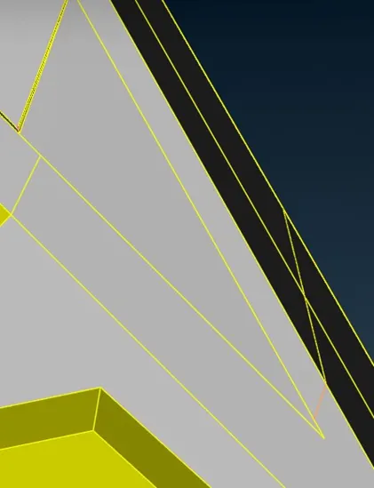
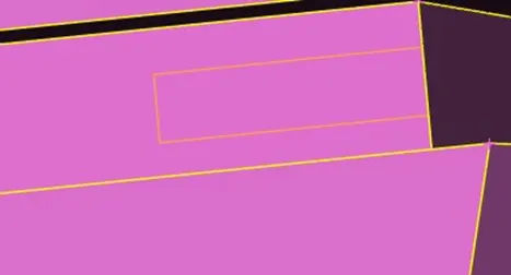
The ridge between the doors were also closed off. And the cuts on the side panels were duly deleted fir a cleaner mesh.
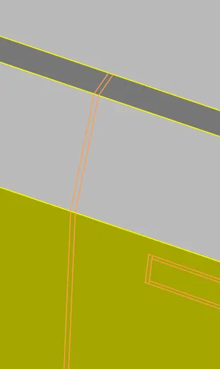
Many unnecessary surface cuts were deleted for a mor continuous, uninterrupted mesh.
After this, PIDs were strategically applied to the different parts, so that the meshing with individual quality criterion.
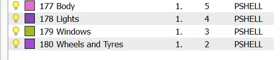
The different PIDs were then meshed with individual criteria. This model was a bigger model in comparison to the BMW M6 model supplied. Thus, the same target lengths could not be used as the number of elements would be quite large and the task would be a lot more computationally intensive.
The quality criteria skewness, min angle quads, max angle quads, min angle trias, max angle trias were common to all the PIDs (taken from the videos referencing the BMW M6 project).
The criteria for the PIDs were as follows:
(The length of perimeters and macros were set as the target lengths for the different PIDs)
Lights; Min length: 1mm, Max length:5mm, Target length: 3mm.
Windows; Min length:3mm, Max length: 9mm, Target length: 6mm.
Wheels and Tyres; Min length:1mm, Max length: 5mm, Target length: 3mm.
As the body PID was in connection to all the other PIDs, the perimeters in contact with the other PIDs were carefully deselected so as to not disturbed the macros that were already meshed.
The perimeter length was then accordingly set to 7mm (as it was the target length).
Body; Min length: 2.5mm, Max length: 11mm, Target length: 7mm.
The Off elements were analyzed in the ‘Hidden’ view. The off elements were dealt with by mostly using the ‘Reconstruct’ option, the ‘Smooth’ option and the ‘Move’ option.
The ‘Reconstruct option was used till the number of off elements reduced to a manageable number. The remaining were rearranged using the move option. The skewed elements were converted to elements that were not meeting the minimum length criteria. These elements were easier to deal with as compared to these not meeting the skewness criteria. The very skewed elements were solved by using the ‘Paste’ options in the ‘Grids’ tab.
After solving the off elements, the next step was to create the wind tunnel.
The dimensions of the wind tunnel are based off on the length of the car.
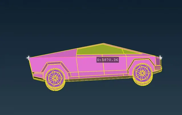
The length of the model was approximately 5870mm.
A new point was inserted just below the car using the ‘Relative’ option in the ‘Points’ tab just below the wheels of the car.
Similarly, a new point was inserted in front of this point at a distance of ‘4X’ (if ‘X’ is the length of the vehicle) in front of the frontmost point.
4*(5870mm)+4145mm=27625mm
(4145mm is the distance of the inserted point from the front of the car).
Similarly, a point was inserted at a distance of ‘6X’ from the rearmost point.
6*(5870mm)+1000mm=36820mm (from the initially inserted point).
(1000mm being the distance of the initially inserted point from the rear of the vehicle).
Similarly, points were inserted on either side at a distance of ‘X’ from the side of the vehicle.
5870mm+1040mm=6910mm (from the initially inserted point).
(1040mm being half the lateral length of the model, as the initially inserted point is halfway along the lateral length.)
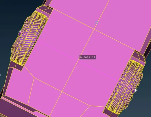
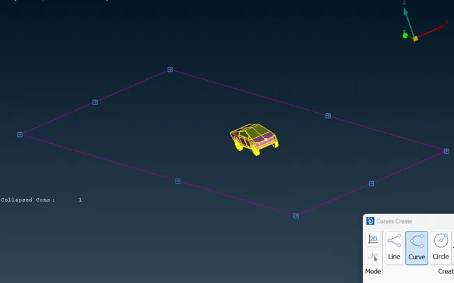
Curves were used to trace along these reference points. Then a new face was created along these curves using the ‘New’ option (‘Fitted’ algorithm).
The top surface of the wind tunnel is supposed to be ‘3X’ distance above the top of the car. This length was worked out to be 20,122mm.
The new face was created using the ‘Offset’ option in the ‘Faces’ tab.
The lateral surfaces were then created using these two faces. The curves and the points were then duly deleted. They were then assigned appropriate PIDs.
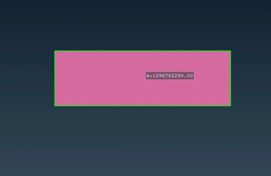
Since these surfaces were much larger than those used for the tunnel enclosing the M6 model, it was decided to use a different meshing criterion.
The target length for the bottom surface would be 80mm and the target length for the top surface would be 160mm. The lengths of the perimeters and the macros were set accordingly.
For the lateral surfaces, the ‘Spacing’ option was used in the ‘Perimeters’ tab.
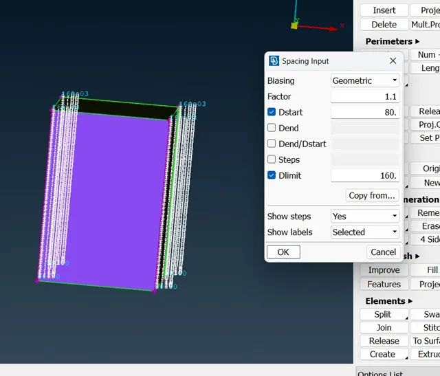
For meshing the sides, the following criteria were inputted:
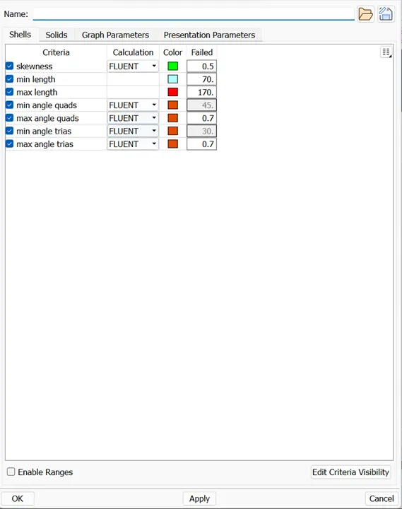
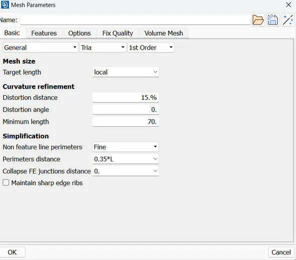
Learning outcome: The nuances of choosing the appropriate quality criteria were explored. A finer mesh captures the details better and reduces chances of meshing errors. The smaller quality criteria that was initially used for the body (4mm as target length, 2mm as min length and 6mm as maximum lenngth) took a very visible strain on the computer and it crashed every time i was trying to reconstruct the mesh to reduce the off elements. Similarly, the quality criteria for the windows was also raised. The quality criteria was chosen to be as small as possible, in order to get a proper surface mesh and to not cause my system to crash while running mesh improvement algorithms.
I also learned how to recognize the areas that could cause issues and to patch them accordingly.
Result and Conclusion : The given model was made free of geometrical errors and the different PIDs assigned were meshed with appropriate quality criteria. A wind tunnel was made to enclose the model with appropriate dimensions and was meshed with appropriate quality criteria.
Link to the ANSA model:
https://drive.google.com/file/d/1SZUkAuvSKJ3-3plzObOjfJkQeZaLSAUT/view?usp=drive_link