Week 8 - Simulation of a backward facing step in OpenFOAM
Given:
In this challenge, you are going to simulate an incompressible-laminar-viscous flow through the backward facing step geometry. You should perform a transient simulation. The solver can be chosen based on the described physics of the flow. You need to explain the entire simulation procedure (how you set up the case). You should also provide explanations to every change you make inside the reference case files obtained from OpenFOAM tutorials. You can choose the inlet velocity shuch that the flow is laminar.
After that, you will perform 2 case studies as described below and compare the results.
Case 1 - Simulate the flow without using any grading factor (i.e., GF = 1)
Case 2 - Simulate the flow with grading factor of 0.2. The cells should be finer near the walls (includig the step wall).
You can use the following mesh parameters but you can feel free to modify these values.
Mesh specification
Number of cells along the x direction (longer dimension) = 200
Number of cells along the longer y direction = 20;
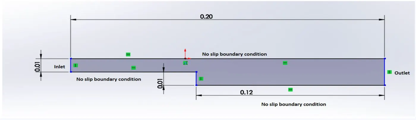
Boundary condition specification
The domain specifications are provided in the following figure.
Procedure:
1.launch the openFoam terminal
2.Open the tutorial and copy the cavity folder into the icoFoam solver. The IcoFoam solver is contained within the incompressible subdirectory.
3.After transferring the cavity folder to the Foam_run folder, navigate to the system folder and update the blockmeshdict. To construct geometry, edit velocity and blocks.
4.Run the blockMesh and paraFoam commands to inspect the produced geometry within paraview.
5.Edit the controldict folder similarly to give time restrictions after editing the blockMesh dict and controldict run the blockMesh command and then run the icoFoam solver tool.
6.The simulation will begin, and you will be able to examine mesh and velocity and pressure changes in Paraview by using the paraFoam command.
Let us see the starting procedure once the OPENFOAM terminal is opened,
>> cd tut >> ls >> cd incompressible >> ls >> cd icoFoam
>> ls >> cp -r cavity/ $FOAM_RUN/ channel_test >> cd $FOAM_RUN
>> cd chaneel_test >> cd system >> gedit blockMesh
Blockmeshdict: The blockMeshDict file serves as input for the blockMesh utility, which generates the mesh based on the specified parameters. Proper configuration of this file is essential for creating a mesh that accurately represents the geometry and meets the requirements of the simulation. This dict includes data about vertices, blocks, and borders. Vertices are used to produce points, which are subsequently linked to form geometry; hence, modify vertices entries to construct the appropriate geometry, and then edit block entries to make faces. After that, run the blockMesh command and then the paraFoam command to inspect the geometry creation in paraview. Edit boundary entries and define or name each face.
/*--------------------------------*- C++ -*----------------------------------*\
  =========                 |
  \\      /  F ield         | OpenFOAM: The Open Source CFD Toolbox
   \\    /   O peration     | Website:  https://openfoam.org
    \\  /    A nd           | Version:  9
     \\/     M anipulation  |
\*---------------------------------------------------------------------------*/
FoamFile
{
    format      ascii;
    class       dictionary;
    object      blockMeshDict;
}
// * * * * * * * * * * * * * * * * * * * * * * * * * * * * * * * * * * * * * //

convertToMeters 1;

vertices
(
   //vertices from points 0 to 10
    (0 0 0)
    (0.08 0 0)
    (0.08 0.005 0)
    (0 0.005 0)
    (0.08 0.01 0)
    (0 0.01 0)
    (0.2 0.01 0)
    (0.2 0.005 0)
    (0.2 0 0)
    (0.2 -0.01 0)
    (0.08 -0.01 0)

    //vertices from points 11 to 21
    (0 0 0.1)
    (0.08 0 0.1)
    (0.08 0.005 0.1)
    (0 0.005 0.1)
    (0.08 0.01 0.1)
    (0 0.01 0.1)
    (0.2 0.01 0.1)
    (0.2 0.005 0.1)
    (0.2 0 0.1)
    (0.2 -0.01 0.1)
    (0.08 -0.01 0.1)
);

blocks
(
    //block 1
    hex (0 1 2 3 11 12 13 14) (80 5 1) simpleGrading (1 1 1)
    //block 2
    hex ( 3 2 4 5 14 13 15 16) (80 5 1) simpleGrading (1 1 1)
    //block 3
    hex (2 7 6 4 13 18 17 15) (120 5 1) simpleGrading (1 1 1)
    //block 4
    hex (1 8 7 2 12 19 18 13) (120 5 1) simpleGrading (1 1 1)
    //block 5
    hex ( 10 9 8 1 21 20 19 12) (120 10 1) simpleGrading (1 1 1)
);

edges
(
);
boundary
(
  outlet
  {
    type patch;
    faces
  (
    (6 17 18 7)
    (8 7 18 19)
    (9 8 19 20)
  );
 }

  inlet
  {
    type patch;
    faces
   (
    (11 14 3 0)
    (14 16 5 3)
   );
  }

  top
  {
    type wall;
    faces
   (
    (15 4 5 16)
    (15 17 6 4)
   );
  }

  bottom
  {
    type wall;
    faces
   (
    (11 0 1 12)
    (21 10 9 20)
   );
  }

   sidestep
  {
   type wall;
   faces
   (
    (21 12 1 10)
   );
  }


   frontface
  {
   type empty;
   faces
   (
     (13 15 16 14)
     (12 13 14 11)
     (20 19 12 21)
     (19 18 13 12)
     (18 17 15 13)
   );
   }

   backface
   {
    type empty;
    faces
    (
      (0 3 2 1)
      (3 5 4 2)
      (2 4 6 7)
      (1 2 7 8)
      (10 1 8 9)
     );
     }
);


mergePatchPairs
(
);

// ************************************************************************* //
controlDict :The controlDict file essentially governs the temporal aspects of the simulation, dictating when to start and stop, the size of each time step, and the frequency of data output. It is a critical component of the OpenFOAM case setup, influencing the accuracy, efficiency, and duration of the simulation process. Proper configuration of the controlDict file is essential to ensure a successful and meaningful CFD simulation. This dict holds time-related information, such as start and finish times and time steps. Change all of the parameters to your liking. The start time is 0 and the end time is 5s, with a time step dt of 0.001.
/*--------------------------------*- C++ -*----------------------------------*\
========= |
\\ / F ield | OpenFOAM: The Open Source CFD Toolbox
\\ / O peration | Website: https://openfoam.org
\\ / A nd | Version: 9
\\/ M anipulation |
\*---------------------------------------------------------------------------*/
FoamFile
{
format ascii;
class dictionary;
location "system";
object controlDict;
}
// * * * * * * * * * * * * * * * * * * * * * * * * * * * * * * * * * * * * * //
application icoFoam;
startFrom startTime;
startTime 0;
stopAt endTime;
endTime 5;
deltaT 0.001;
writeControl timeStep;
writeInterval 20;
purgeWrite 0;
writeFormat ascii;
writePrecision 6;
writeCompression off;
timeFormat general;
timePrecision 6;
runTimeModifiable true;
// ************************************************************************* //Transport properties – next we change value of viscosity to 0.0001, so that we get reynolds number for laminar flow. Re = (density.u.viscosity)/ L
/*--------------------------------*- C++ -*----------------------------------*\
========= |
\\ / F ield | OpenFOAM: The Open Source CFD Toolbox
\\ / O peration | Website: https://openfoam.org
\\ / A nd | Version: 9
\\/ M anipulation |
\*---------------------------------------------------------------------------*/
FoamFile
{
format ascii;
class dictionary;
location "constant";
object transportProperties;
}
// * * * * * * * * * * * * * * * * * * * * * * * * * * * * * * * * * * * * * //
nu [0 2 -1 0 0 0 0] 1e-5;
// ************************************************************************* //Velocity: Set velocity settings for each boundary. The top and bottom faces have no slip, the inlet and exit have a neumann boundary condition, and the front and back faces have no slip. When we want 2D simulation on 3dD geometry, we employ the empty condition, which implies they don't record velocity and pressure changes.
/*--------------------------------*- C++ -*----------------------------------*\
  =========                 |
  \\      /  F ield         | OpenFOAM: The Open Source CFD Toolbox
   \\    /   O peration     | Website:  https://openfoam.org
    \\  /    A nd           | Version:  9
     \\/     M anipulation  |
\*---------------------------------------------------------------------------*/
FoamFile
{
    format      ascii;
    class       volVectorField;
    object      U;
}
// * * * * * * * * * * * * * * * * * * * * * * * * * * * * * * * * * * * * * //

dimensions      [0 1 -1 0 0 0 0];

internalField   uniform (0.1 0 0);

boundaryField
{
    inlet
    {
        type            fixedValue;
        value           uniform (0.2 0 0);
    }

    top
    {
        type            noSlip;
    }

    bottom
    {
        type            noSlip;
    }

    sidestep
    {
        type            noSlip;
    }

    frontface
    {
        type            empty;
    }

    backface
    {
        type            empty;
    }

    outlet
    {
        type            zeroGradient;
    }
}

// ************************************************************************* //Pressure: This dict, which can be located in the 0 folder, defines pressure conditions at all borders, with the inlet and outflow utilising the Neumann boundary condition. Neumann boundary conditions define either velocity or pressure for the inlet or outflow.
/*--------------------------------*- C++ -*----------------------------------*\
========= |
\\ / F ield | OpenFOAM: The Open Source CFD Toolbox
\\ / O peration | Website: https://openfoam.org
\\ / A nd | Version: 9
\\/ M anipulation |
\*---------------------------------------------------------------------------*/
FoamFile
{
format ascii;
class volScalarField;
object p;
}
// * * * * * * * * * * * * * * * * * * * * * * * * * * * * * * * * * * * * * //
dimensions [0 2 -2 0 0 0 0];
internalField uniform 0;
boundaryField
{
inlet
{
type zeroGradient;
}
top
{
type zeroGradient;
}
bottom
{
type zeroGradient;
}
sidestep
{
type zeroGradient;
}
frontface
{
type empty;
}
backface
{
type empty;
}
outlet
{
type fixedValue;
value uniform 0;
}
}OUTPUTS:
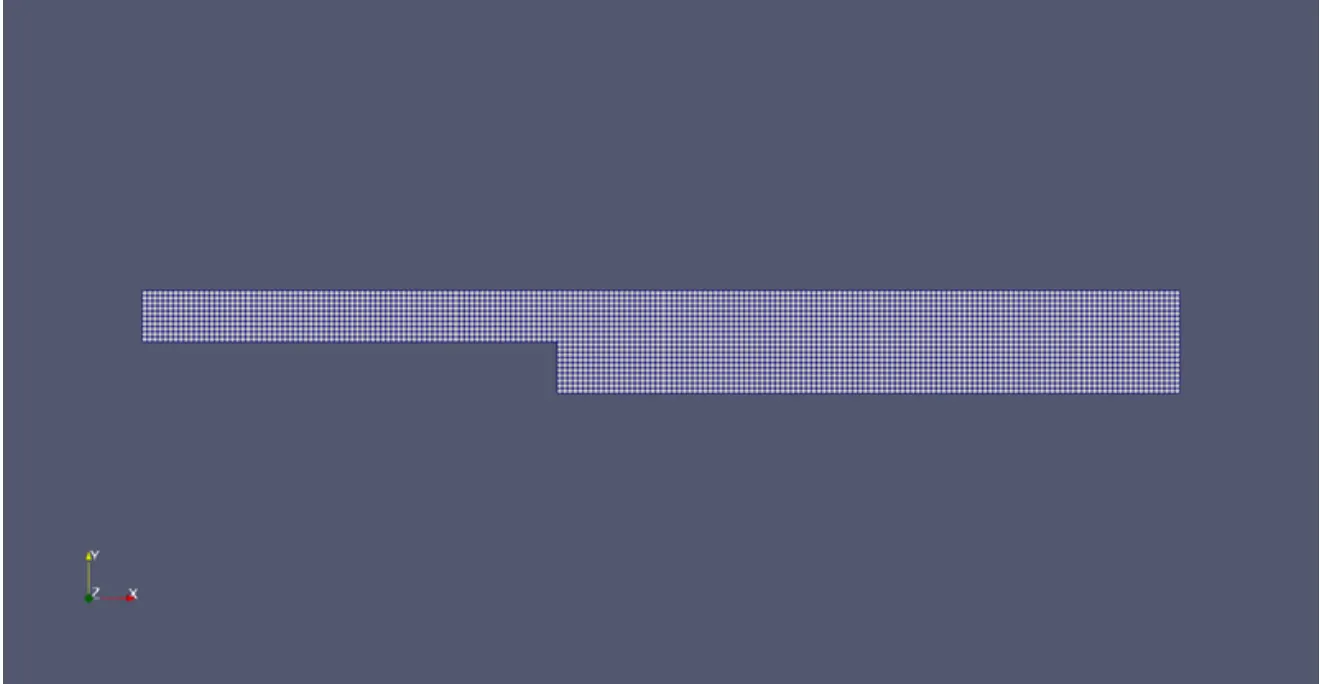
Firstly let us see the Mesh Without Grading.The image below shows mesh without grading,
The Velocity contour and Pressure contour simulations link are attached,
https://drive.google.com/file/d/1Jcpi1q3qpQTeXvdgeT-OiXOPz7CUlIB6/view?usp=sharing
https://drive.google.com/file/d/1lvk5zKjth6FTNO7WHdTXmEpg9OiJjf2r/view?usp=sharing
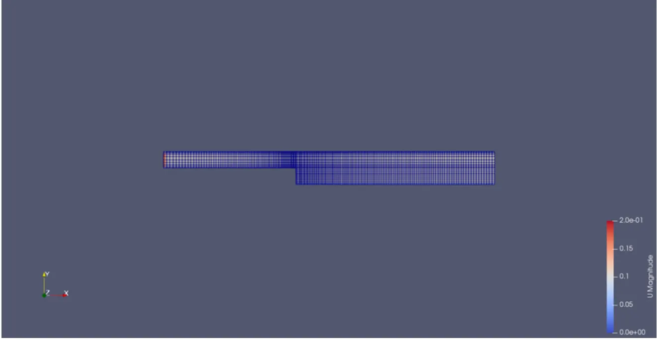
Only the grading values in block entries of blockMeshdict need to be altered in this simulation to get the desired grading on faces. In this instance, a denser mesh at the side step is preferred.Only the grading values in block entries of blockMeshdict need to be altered in this simulation to get the desired grading on faces. In this instance, a denser mesh at the side step is preferred.so we use simulation with grading 0.2.
*--------------------------------*- C++ -*----------------------------------*\
  =========                 |
  \\      /  F ield         | OpenFOAM: The Open Source CFD Toolbox
   \\    /   O peration     | Website:  https://openfoam.org
    \\  /    A nd           | Version:  9
     \\/     M anipulation  |
\*---------------------------------------------------------------------------*/
FoamFile
{
    format      ascii;
    class       dictionary;
    object      blockMeshDict;
}
// * * * * * * * * * * * * * * * * * * * * * * * * * * * * * * * * * * * * * //

convertToMeters 1;

vertices
(
   //vertices from points 0 to 10
    (0 0 0)
    (0.08 0 0)
    (0.08 0.005 0)
    (0 0.005 0)
    (0.08 0.01 0)
    (0 0.01 0)
    (0.2 0.01 0)
    (0.2 0.005 0)
    (0.2 0 0)
    (0.2 -0.01 0)
    (0.08 -0.01 0)

    //vertices from points 11 to 21
    (0 0 0.1)
    (0.08 0 0.1)
    (0.08 0.005 0.1)
    (0 0.005 0.1)
    (0.08 0.01 0.1)
    (0 0.01 0.1)
    (0.2 0.01 0.1)
    (0.2 0.005 0.1)
    (0.2 0 0.1)
    (0.2 -0.01 0.1)
    (0.08 -0.01 0.1)
);

blocks
(
    //block 1
    hex (0 1 2 3 11 12 13 14) (80 5 1) simpleGrading (0.2 3 1)
    //block 2
    hex ( 3 2 4 5 14 13 15 16) (80 5 1) simpleGrading (0.2 0.2 1)
    //block 3
    hex (2 7 6 4 13 18 17 15) (120 5 1) simpleGrading (3 0.2 1)
    //block 4
    hex (1 8 7 2 12 19 18 13) (120 5 1) simpleGrading (3 3 1)
    //block 5
    hex ( 10 9 8 1 21 20 19 12) (120 10 1) simpleGrading (3 1 1)
);

edges
(
);
boundary
(
  outlet
  {
    type patch;
    faces
  (
    (6 17 18 7)
    (8 7 18 19)
    (9 8 19 20)
  );
 }

  inlet
  {
    type patch;
    faces
   (
    (11 14 3 0)
    (14 16 5 3)
   );
  }

  top
  {
    type wall;
    faces
   (
    (15 4 5 16)
    (15 17 6 4)
   );
  }

  bottom
  {
    type wall;
    faces
   (
    (11 0 1 12)
    (21 10 9 20)
   );
  }

   sidestep
  {
   type wall;
   faces
   (
    (21 12 1 10)
   );
  }


   frontface
  {
   type empty;
   faces
   (
     (13 15 16 14)
     (12 13 14 11)
     (20 19 12 21)
     (19 18 13 12)
     (18 17 15 13)
   );
   }

   backface
   {
    type empty;
    faces
    (
      (0 3 2 1)
      (3 5 4 2)
      (2 4 6 7)
      (1 2 7 8)
      (10 1 8 9)
     );
     }
);


mergePatchPairs
(
);
Now let us see the Mesh with grading,
The Velocity contour and Pressure contour simulations link are attached,
https://drive.google.com/file/d/1jFhN1WdN7jhMGv5vP8gjU_DPfzd7W84Z/view?usp=sharing
https://drive.google.com/file/d/1rSlEk488SgbFCeAvFSKOeLYrcGISGcOs/view?usp=sharing
Plots:
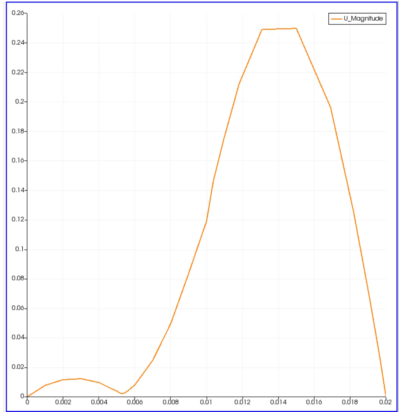
The plotting for velocity was done and the image shows velocity plot with no grading,
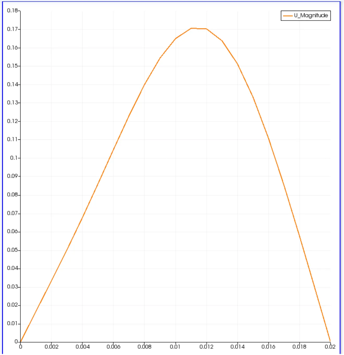
This image shows velocity plot with grading 0.2.
Results and Discussion:
1.By increasing the simple grading factor from 0.2, the mesh becomes finer and the solution becomes extremely exact.
2.Overall, when the size of the basic grading factor (mesh size) is changed, the results stay nearly the same.
3.A lower meshing grading factor results in a shorter execution time.
4.I learned how to conduct simulations in the openFoam terminal and alter the blockMeshdict and controldict.