Week 8 - Simulation of a backward facing step in OpenFOAM
Aim:
In this challenge, you are going to simulate an incompressible-laminar-viscous flow through the backward facing step geometry. You should perform a transient simulation. The solver can be chosen based on the described physics of the flow. You need to explain the entire simulation procedure (how you set up the case). You should also provide explanations to every change you make inside the reference case files obtained from OpenFOAM tutorials. You can choose the inlet velocity shuch that the flow is laminar.
Objective:
After that, you will perform 2 case studies as described below and compare the results.
Case 1 - Simulate the flow without using any grading factor (i.e., GF = 1)
Case 2 - Simulate the flow with grading factor of 0.2. The cells should be finer near the walls (includig the step wall).
You can use the following mesh parameters but you can feel free to modify these values.
Answer:
Geometry:
The given geometry & boundary conditions are shown in the below image. The faces has been defined in the boundary conditions file based on the following inputs. Dimensions mentioned in the below image is in meter.
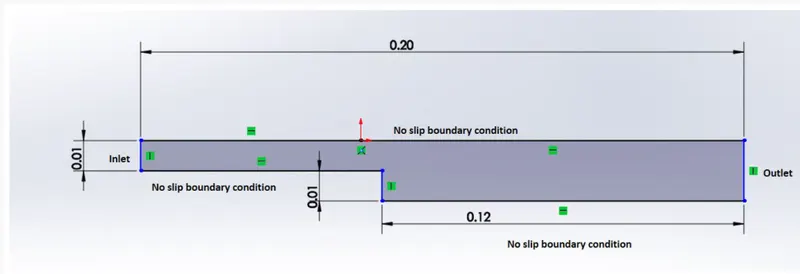
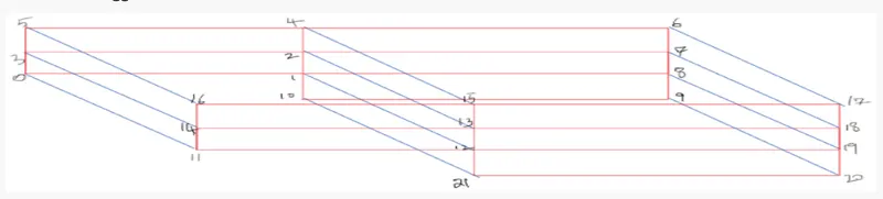
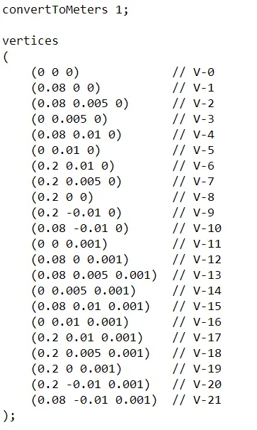
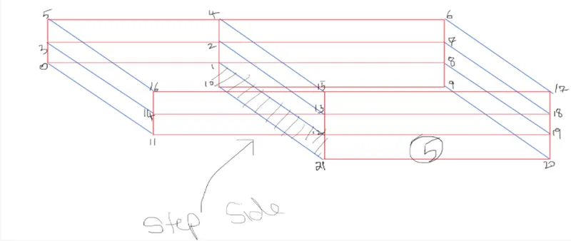
To made the geometry in the OpenFOAM, following geometry has been created with defined vertex number to indicate the faces & blocks in the blockMeshDict file.
Blocks Numbering

Vertex Numbering
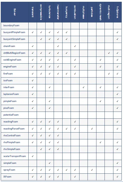
To perform simulation which is incompressible-laminar-viscous in nature, the suitable solver is icoFoam in OpenFOAM. Following is the table provided on the openfoam website to explain the functionality of each & each every solver availble in the openFOAM.
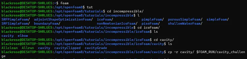
The casefiles of cavity tutorial has been copied from the installed directory to the "run" folder using following command. Initial commands is to navigate the WSL2 to the tutorial folder to copy the cavity casefiles. Name has been change from cavity to cavity_challenge.
Creating Geometry using the vertices location in blockMeshDict file located in the system folder of the case. The blockMesh is used for creating multiblock geometry. convertToMeters indicates the conversion ratio for the unit of the size. In this case, as we are inserting in "meter" only, so we have kept it to 1.
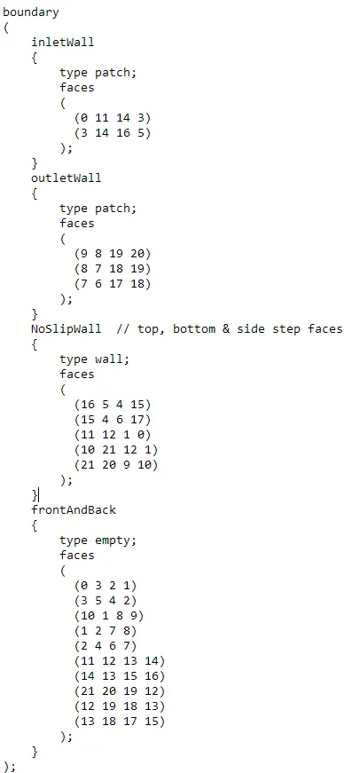
The boundaries of the geometries has been defined as follows & divided them into inlet, outlet, NoSlip wall, and front and back faces. First sert of images indicates the boundary conditions on the geometry & later faces has been defined using the vertex numbering.
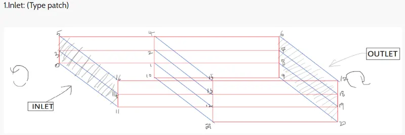
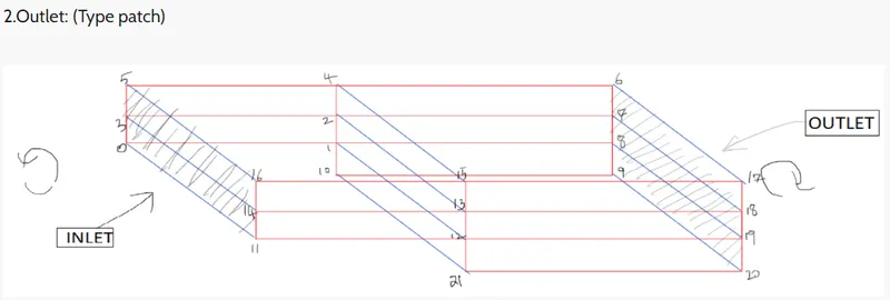
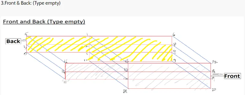
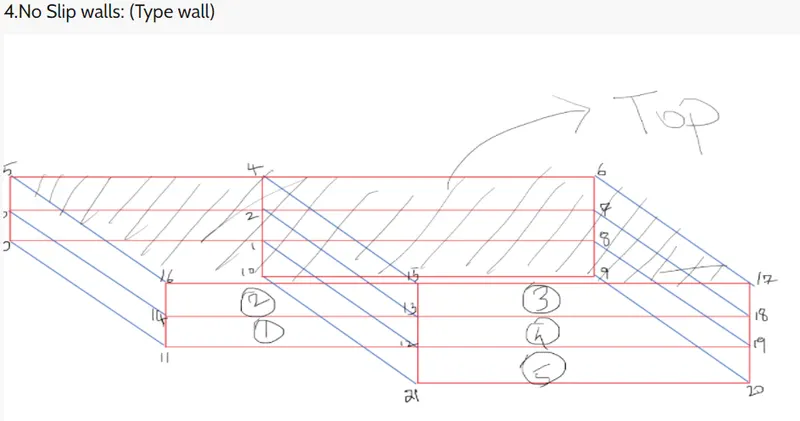
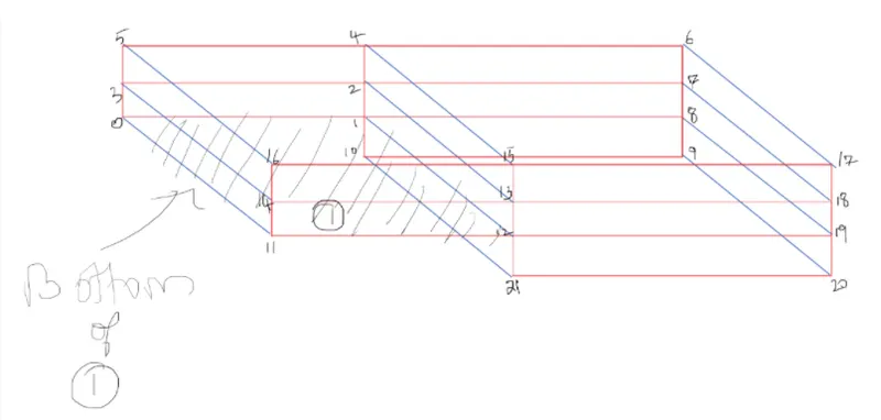
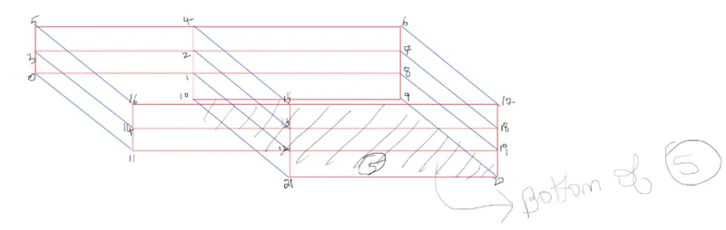
All above boundary conditions has been defined in following text file with their respective titles.
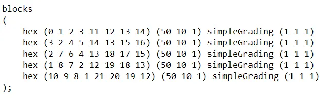
blocks of the geometry has been defined in the same file in the following way. The simpleGrading kept it uniform for the first simulation while it has been changed for the second simulation. Beside hexa block, number of mesh elements in the x, y & z direction has been mentioned to create the mesh on the geometry.
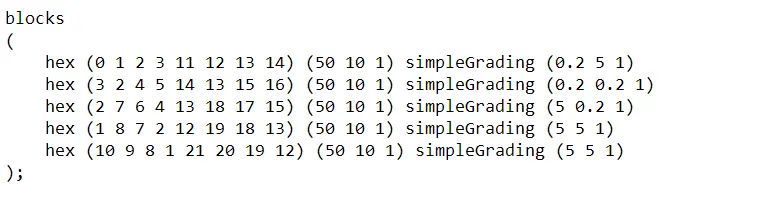
And at last, simpleGrading defines the mesh stretching in particular direction. In first simulation we kept the grading uniform while we changed in the second simulation in x & y direction.
For first simulation
For second simulation
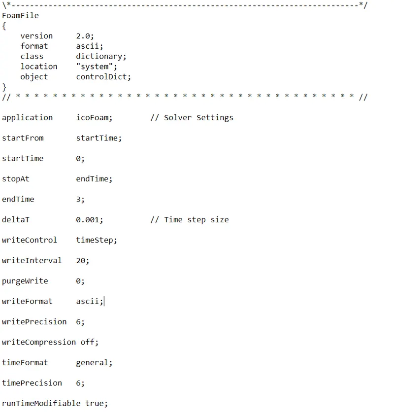
In system folder, there is one more file called controlDict which controlled the simulation process. In this file, we have changed start & end time & also time step size (deltaT). Remaining options has been kept same.
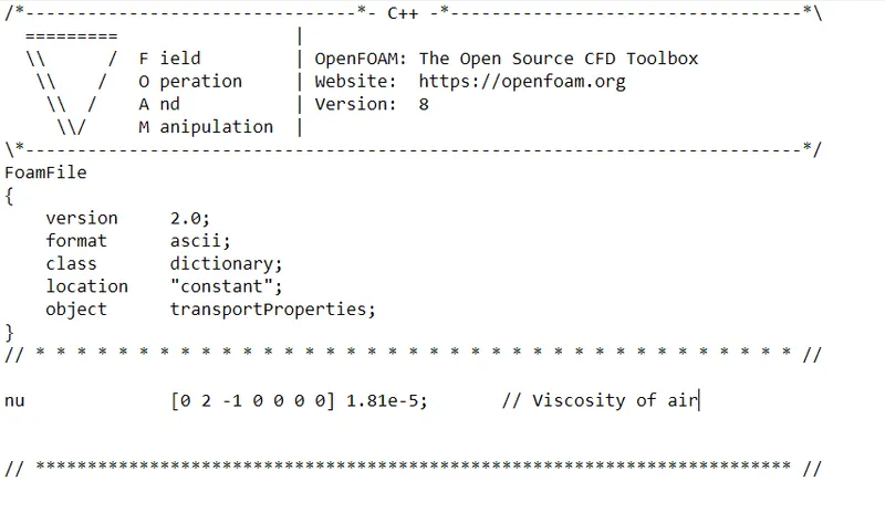
In transport properties file located in constant folder, the viscosity of air has been changed.
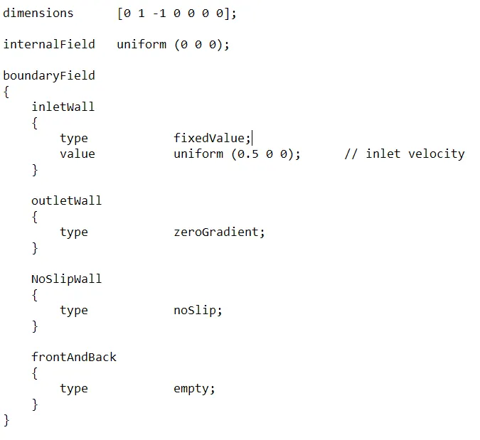
To setup intial condition, files of "U" & "p" has been modified. U stands for velocity & p stands for pressure inputs.
In the U file, inlet velocity has been changed.
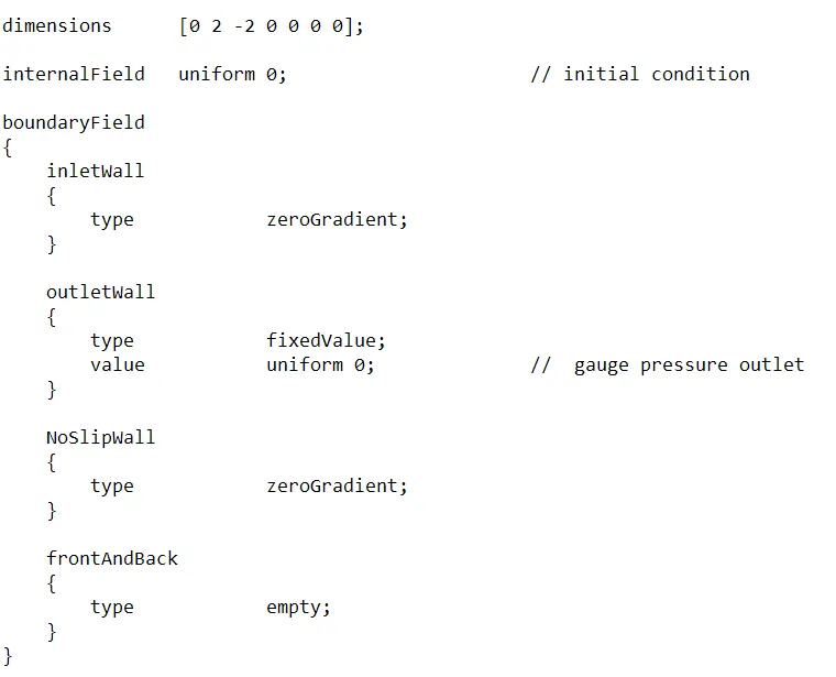
Initial pressure condition has also been changed in following manner.
Mesh:
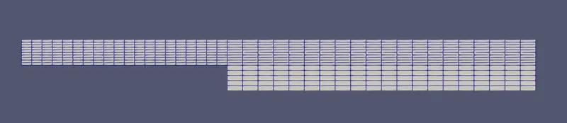
The mesh has been performed on the geometry using "blockMesh" command. To review mesh, paraview software as been used. First mesh image is for the case 1 with uniform grading while the second image shows with grading mentioned in the above sections. The grading used in the second case to capture the flow details nearer the walls more effectively by using finer mesh.
Uniform grading
With grading - finer mesh near wall

Processing & Post-processing:
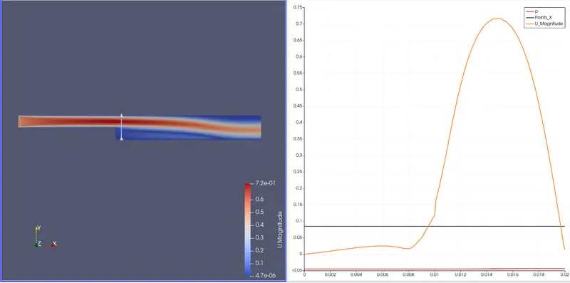
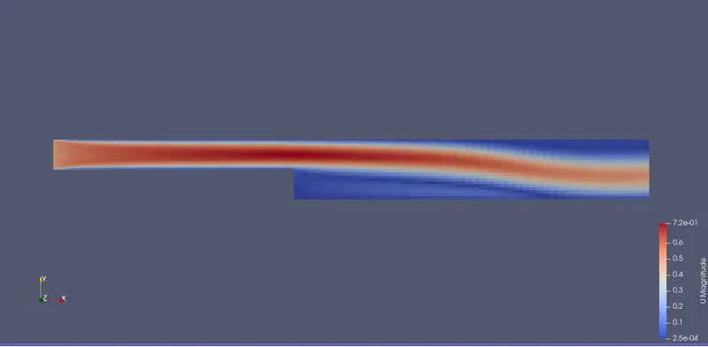
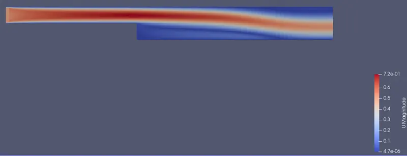
Transient simulation has been processed with 0.5 m/s inlet velocity using the "icoFoam" command. The results are as follows:
For case 1:
For case 2:
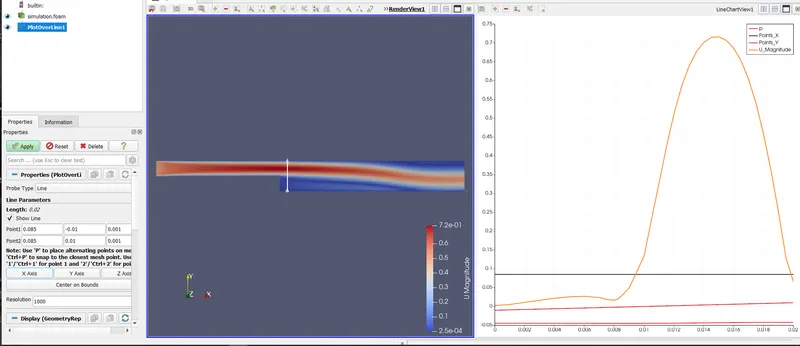
Using the filter called plot over line, vertical line has been created the location of 0.085m in x direction in both cases. The graph that represent the change in velocity on that line.
For case 1:
For case 2: