Simulation of a backward facing step in OpenFOAM
Objective:
- To simulate the backward facing step in OpenFoam.
Problem Statement:
In this project, we are going to simulate an incompressible-laminar-viscous flow through the backward facing step geometry. we will be perform a transient simulation. The solver can be chosen based on the described physics of the flow. You need to explain the entire simulation procedure (how you set up the case). You should also provide explanations to every change you make inside the reference case files obtained from OpenFOAM tutorials. You can choose the inlet velocity shuch that the flow is laminar.
After that, you will perform 2 case studies as described below and compare the results.
Case 1 - Simulate the flow without using any grading factor (i.e., GF = 1)
Case 2 - Simulate the flow with grading factor of 0.2. The cells should be finer near the walls (includig the step wall).
You can use the following mesh parameters but you can feel free to modify these values.
Mesh specification
- Number of cells along the x direction (longer dimension) = 200
- Number of cells along the longer y direction = 20;
Boundary condition specification
The domain specifications are provided in the following figure.
Desired output
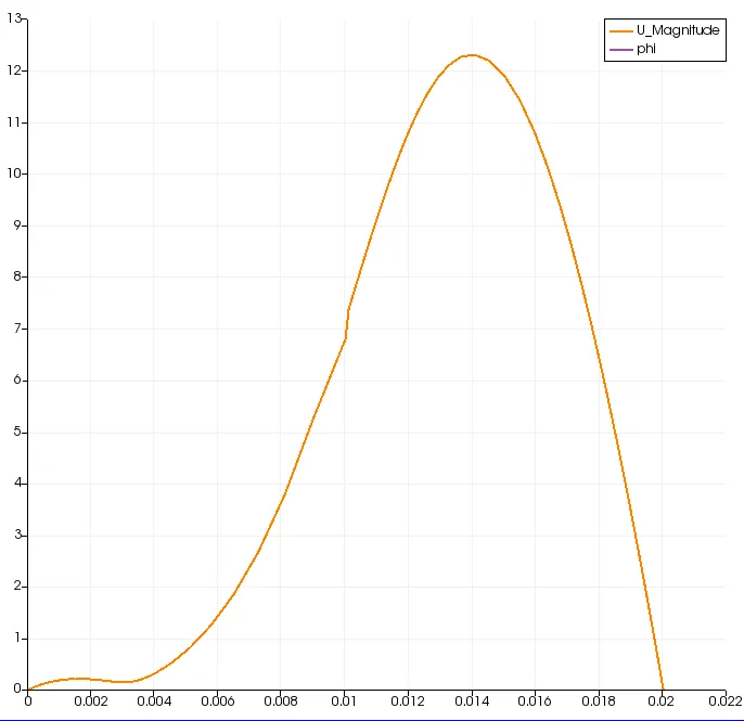
- Measure the velocity profile at 0.085 m from the inlet of the geometry for both case studies and compare. You can use the plot over line tool for this.
- Explain why Grading/Growth factor is essential for meshing.
Procedure:
In order to simulate the incompressible-laminar-viscous flow in the geometry asked in the problem statement we need to follow the steps that is required to run the simulation in OpenFoam:
- Copying the related file from the tutorial folder to an another folder.
- Creating the geometry.
- Specifying the value of primitive variables (pressure and velocity in this case).
- Creating and Checking the mesh to the geometry.
- Run the simulation with all the cases.
1. Copying the related file from the tutorial folder to another folder.
In the first step, we are going to access the the cavity file which is located inside the icoFoam solver. We are using icoFoam solver because it is built for incompressible-laminar-flow.
To reach the target file we should be following the steps shown below using the terminal window:
tut `->` cd incompressible `->`cd icoFoam `->` cd cavity.
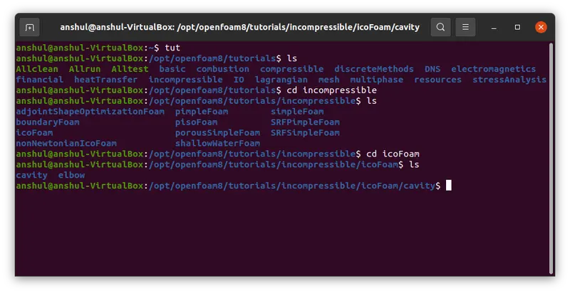
After accessing the required folder we need to copy the cavity folder to a run folder which is located outside the OpenFoam folder as we cannot run the tutorial files inside the OpenFoam folder.
To do this task,we must go thorugh the following steps in the terminal:
- Use command cp -r cavity $FOAM_RUN/cavity_test. This wiil copy the cavity file to a different folder called run outside the OpenFoam.
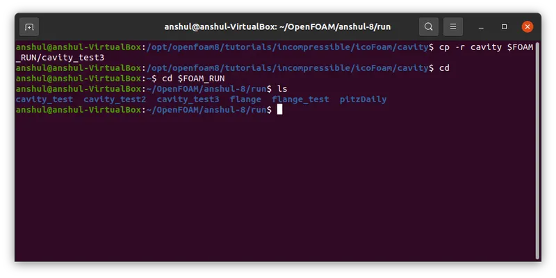
Hence our target file is copied to the folder where we can run our simulation effortlessly.
2. Creating the Geometry:
We are going to create the geometry in OpenFoam as shown in the problem statement:
To create the geometry as shown in the figure, we need to edit the blockMeshDict file that is available in the system folder of the case setup.
We can consider creating the geometry using 5 blocks as shown in the figure below,
The Isometric View,
Now let’s, start indexing the Vertices on the Back side of the Blocks, Since openFoam uses C++ programming, we start the index from “0”. (The Numbering of the vertices can be varied according to your comfort)
Similarly, the indexing for the frontside of the Blocks are,
To View the Bigger Picture,
Finally, to define the blocks, we need to specify the right order of vertex indices
For example:
to create the 1st Block for this case,
hex (0 1 2 3 11 12 13 14) (1 1 1) simpleGrading (1 1 1)
Similarly proceed by defining the vertices of the other blocks in the Geometry.
To View geometry that you have created, clear out all the entries inside the boundary section of the blockMeshDict file and execute the blockMesh command in the terminal.
Now open paraview and view the geometry that you have created.
Meshing:
Now to mesh the geometry fill in the number of cells in x, y and z direction inside the second parenthesis of the Hex command,
i.e., hex(0 1 2 3 11 12 13 14) (10 10 1) simplegrading(1 1 1).
since this is a 2D problem, increasing the number of cells in the z direction, doesn’t make sense. To view the mesh in paraFoam, select the surface with edges option and view the mesh.
Similarly to refine the mesh near the walls of the geometry, you need to play around with the numbers in the third parenthesis. We leave that for you to figure out, how It can be done.
Boundary Conditions:
Before we run the simulations, we need to specify the initial and boundary conditions.
The given boundary conditions are,
1.Inlet: (Type patch)
The faces that contribute to inlet boundary are shown above. If we are looking at these faces from the outside, the definition of inlet boundary will be in counter-clockwise direction,
(0 11 14 3)
(3 14 16 5)
2.Outlet: (Type patch)
Similarly, we have 3 faces contributing to the outlet boundary condition. Since we are viewing the faces from outside, hence the definition of the outlet boundary will be in counter-clockwise direction,
(9 8 19 20)
(8 7 18 19)
(7 6 17 18)
Now for the other boundary look at the images below and repeat the steps to define the boundaries.
3.Front & Back: (Type empty)
4.No Slip walls: (Type wall)
After defining the boundaries correctly, to check if you have given defined them correctly, execute the blockMesh command in the terminal.Now open paraFoam, select all the patches and click apply. You will now be able to see the boundary conditions that have been applied to the geometry.
Now we are going to implement the above explained concept in the terminal,
- Opening the blockMeshDict library using the terminal.
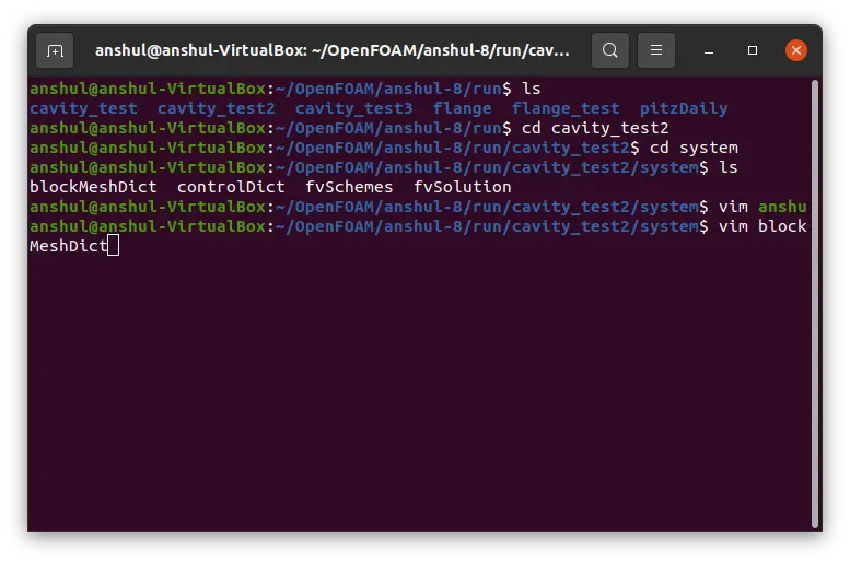
- The editor window is now opened where we have to specify the coordinates for all the verteces and specify the inlet,outlet and fixed walls of the geometry.
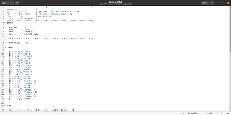
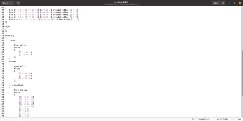
/*--------------------------------*- C++ -*----------------------------------*
  =========                 |
  \      /  F ield         | OpenFOAM: The Open Source CFD Toolbox
   \    /   O peration     | Website:  https://openfoam.org
    \  /    A nd           | Version:  8
     \/     M anipulation  |
*---------------------------------------------------------------------------*/
FoamFile
{
    version     2.0;
    format      ascii;
    class       dictionary;
    object      blockMeshDict;
}
// * * * * * * * * * * * * * * * * * * * * * * * * * * * * * * * * * * * * * //

convertToMeters 0.01;

vertices
(
    (0 0 0) // Vertex 0
    (8 0 0) // Vertex 1
    (8 0.5 0) // Vertex 2
    (0 0.5 0) // Vertex 3
    (8 1 0) // Vertex 4
    (0 1 0) // Vertex 5
    (20 1 0) // Vertex 6
    (20 0.5 0) // Vertex 7
    (20 0 0) // Vertex 8
    (20 -1 0) // Vertex 9
    (8 -1 0) // Vertex 10
    (0 0 0.1) // Vertex 11
    (8 0 0.1) // Vertex 12
    (8 0.5 0.1) // Vertex 13
    (0 0.5 0.1) // Vertex 14
    (8 1 0.1) // Vertex 15
    (0 1 0.1) // Vertex 16
    (20 1 0.1) // Vertex 17
    (20 0.5 0.1) // Vertex 18
    (20 0 0.1) // Vertex 19
    (20 -1 0.1) // Vertex 20
    (8 -1 0.1) // Vertex 21
);

blocks
(
    hex (0 1 2 3 11 12 13 14) (200 20 1) simpleGrading (1 1 1)
    hex (3 2 4 5 14 13 15 16) (200 20 1) simpleGrading (1 1 1)
    hex (2 7 6 4 13 18 17 15) (200 20 1) simpleGrading (1 1 1)
    hex (1 8 7 2 12 19 18 13) (200 20 1) simpleGrading (1 1 1)
    hex (10 9 8 1 21 20 19 12) (200 20 1) simpleGrading (1 1 1)
);

edges
(
);

boundary
(
    inlet
    {
        type wall;
        faces
        (
            (0 11 14 3)
            (3 14 16 5)
        );
    }
    outlet
    {
        type wall;
        faces
        (
            (9 8 19 20)
            (8 7 18 19)
            (7 6 17 18)
        );
    }
    frontAndBack
    {
        type empty;
        faces
        (
            (11 12 13 14)
            (14 13 15 16)
            (13 18 17 15)
            (12 19 18 13)
            (21 20 19 12)
            (0 3 2 1)
            (3 5 4 2)
            (2 4 6 7)
            (1 2 7 8)
            (10 1 8 9)
        );
    }
    fixedWalls
    {
    	type wall;
    	faces
    	(
    		(5 16 15 4)
    		(0 1 12 11)
    		(4 15 17 6)
    		(10 9 20 21)
    		(10 21 12 1)
    	);
    }
);

mergePatchPairs
(
);

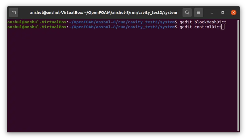
// ************************************************************************* //- Now we are going to the controlDict library to specify the starting and ending time of the simulation and number of time steps.
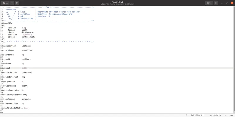
/*--------------------------------*- C++ -*----------------------------------*
  =========                 |
  \      /  F ield         | OpenFOAM: The Open Source CFD Toolbox
   \    /   O peration     | Website:  https://openfoam.org
    \  /    A nd           | Version:  8
     \/     M anipulation  |
*---------------------------------------------------------------------------*/
FoamFile
{
    version     2.0;
    format      ascii;
    class       dictionary;
    location    "system";
    object      controlDict;
}
// * * * * * * * * * * * * * * * * * * * * * * * * * * * * * * * * * * * * * //

application     icoFoam;

startFrom       startTime;

startTime       0;

stopAt          endTime;

endTime         2;

deltaT          0.001;

writeControl    timeStep;

writeInterval   20;

purgeWrite      0;

writeFormat     ascii;

writePrecision  6;

writeCompression off;

timeFormat      general;

timePrecision   6;

runTimeModifiable true;


// ************************************************************************* //
Hence the geometry of the backward facing step is created.
3. Specifying the values of primitive variables (pressure and velocity):
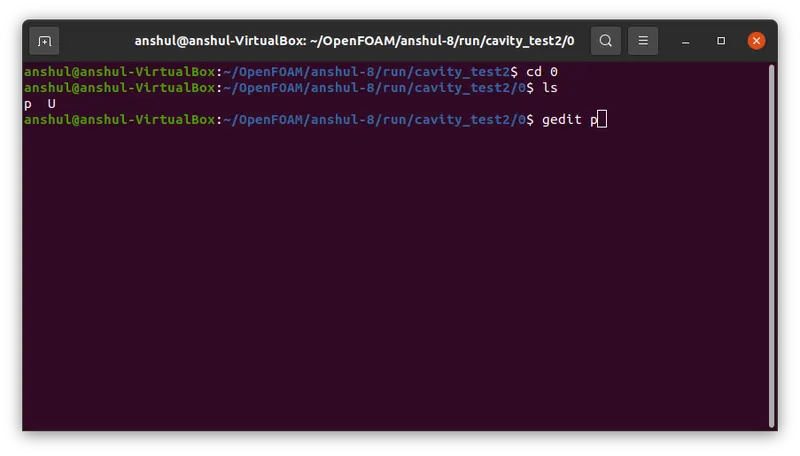
In this step we need to access the folder name '0' inside the cavity_test file and edit text editor file of both the variables.
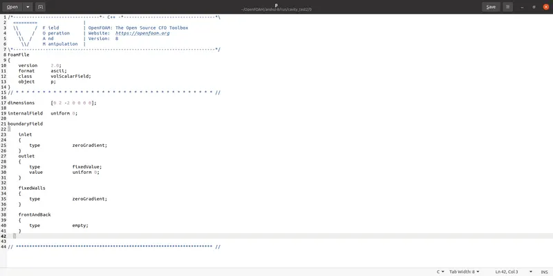
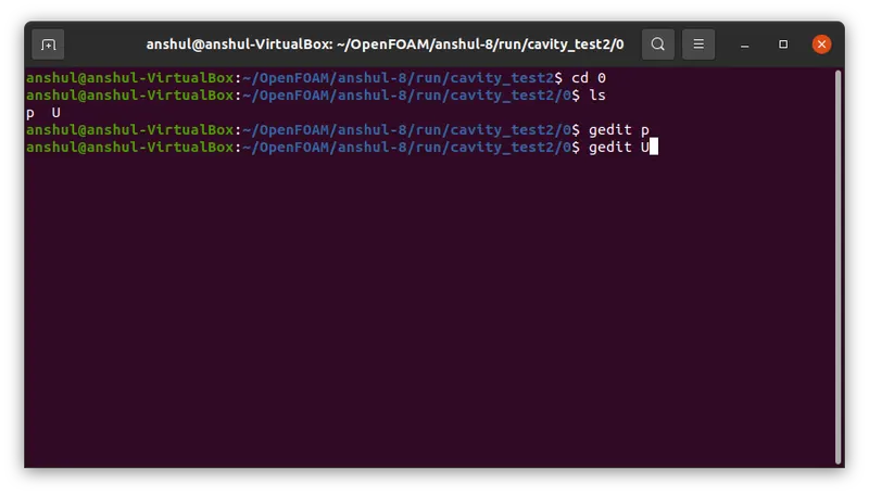
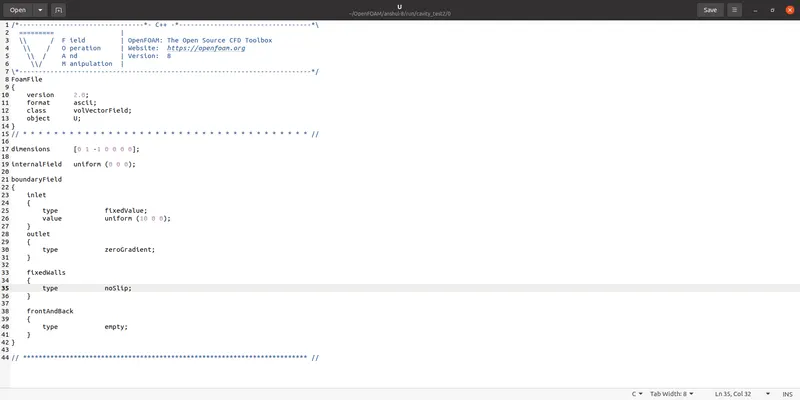
4. Creating and checking the mesh:
- To create the mesh we will use the blockmMesh command and execute it.
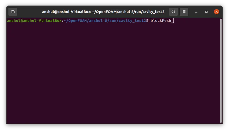
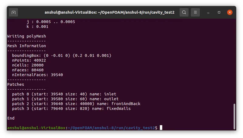
- To check the mesh is Ok we will use the checkMesh command.
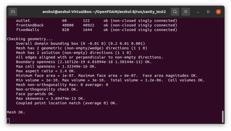
Let's see the mesh in paraFoam.
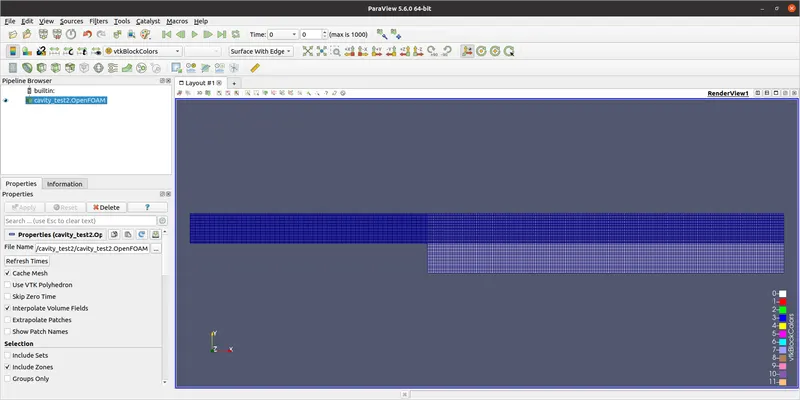
The Mesh is generated.
5. Running the Simulation:
Case 1: Grading factor = 1
For grading factor 1,
    hex (0 1 2 3 11 12 13 14) (200 20 1) simpleGrading (1 1 1)
    hex (3 2 4 5 14 13 15 16) (200 20 1) simpleGrading (1 1 1)
    hex (2 7 6 4 13 18 17 15) (200 20 1) simpleGrading (1 1 1)
    hex (1 8 7 2 12 19 18 13) (200 20 1) simpleGrading (1 1 1)
    hex (10 9 8 1 21 20 19 12) (200 20 1) simpleGrading (1 1 1)
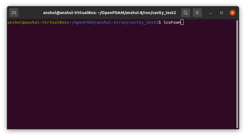
To solve the geometry we will use icoFoam solver as it is suitable for incompressible laminar flow. We will execute the icoFoam command in the terninal window to solve the geometry.
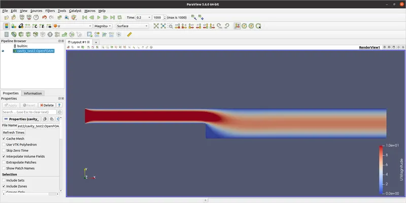
Velocity Distribution along the geometry:
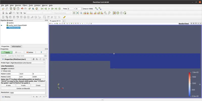
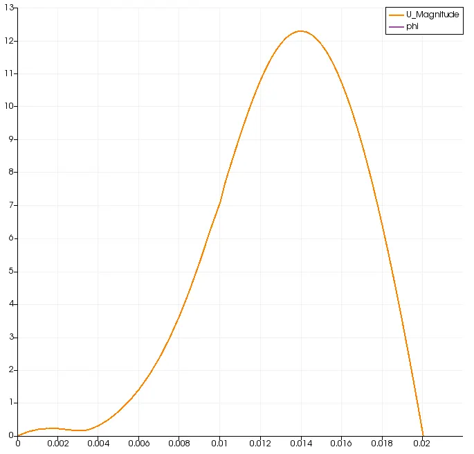
Calculating the velocity at 0.085 m:
Pressure Distribution along the geometry:

Case 2:
For grading factor 0.2,
    hex (0 1 2 3 11 12 13 14) (200 20 1) simpleGrading (0.2 5 1)    // Block 1
    hex (3 2 4 5 14 13 15 16) (200 20 1) simpleGrading (0.2 0.2 1)   // Block 2
    hex (2 7 6 4 13 18 17 15) (200 20 1) simpleGrading (5 0.2 1)    // Block 3
    hex (1 8 7 2 12 19 18 13) (200 20 1) simpleGrading (5 5 1)     // Block 4
    hex (10 9 8 1 21 20 19 12) (200 20 1) simpleGrading (5 5 1)    // Block 5
Mesh generated with grading factor 0.2:

Velocity Distribution along the geometry at a distance 0.085m from the inlet:

Pressure Distribution along the geometry:

Conclusion:
- The simulation of the incompressible laminar flow is done.
- The simulation ran by two cases where scaling factor was 1 at the first case and 0.2 at the second case.
- The case two mesh is more finer than the case one mesh.
- The results obtained from the case two is more accurate than the case one.