Week 8 - Simulation of a backward facing step in OpenFOAM
Objective: To perform transient incompressible-laminar-viscous flow through the backward-facing step geometry in two cases one with a grading factor of one & the next one with a grading factor of 0.2.
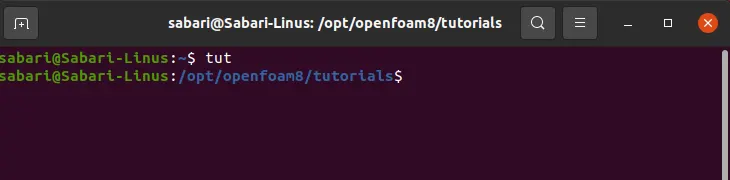
To start with the simulations, the terminal window is opened by pressing ctrl+alt+T on the keyboard. Browsing to the tutorial folder of OpenFOAM is done by typing the command "tut".
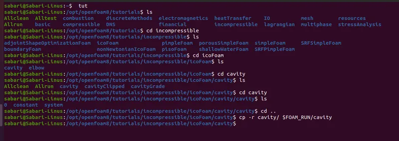
Inside the tutorial folder, the browsing is done into the following folders incompressible -> icoFoam-> cavity -> cavity for locating the needed tutorial files. These files are then copied to the OpenFOAM run folder using the copy command.
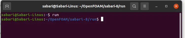
After copying, Browing to the run folder of OpenFOAM is performed by run command in terminal
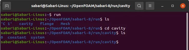
Inside the run folder, the copied folders are again browsed.
Case -1: Flow simulation without using any grading factor (i.e., GF = 1)
First, we need to modify the blockMeshDict file in the system folder as per our geometry. Opening of the blockMeshDict file is performed by using the gedit commands in the terminal
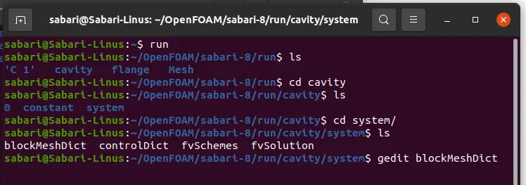
blockMeshdict file:
Modified blockMeshdict file is written below
/*--------------------------------*- C++ -*----------------------------------*\
  =========                 |
  \\      /  F ield         | OpenFOAM: The Open Source CFD Toolbox
   \\    /   O peration     | Website:  https://openfoam.org
    \\  /    A nd           | Version:  8
     \\/     M anipulation  |
\*---------------------------------------------------------------------------*/
FoamFile
{
    version     2.0;
    format      ascii;
    class       dictionary;
    object      blockMeshDict;
}
// * * * * * * * * * * * * * * * * * * * * * * * * * * * * * * * * * * * * * //

convertToMeters 1;

vertices
(
    (0 0 0)          //0
    (0.08 0 0)       //1
    (0.08 0.005 0)   //2
    (0 0.005 0)      //3
    (0.08 0.01 0)    //4
    (0 0.01 0)       //5
    (0.2 0.01 0)     //6
    (0.2 0.005 0)    //7
    (0.2 0 0)        //8
    (0.2 -0.01 0)     //9
    (0.08 -0.01 0)    //10

    (0 0 0.001)          //11
    (0.08 0 0.001)       //12
    (0.08 0.005 0.001)   //13
    (0 0.005 0.001)      //14
    (0.08 0.01 0.001)    //15
    (0 0.01 0.001)       //16
    (0.2 0.01 0.001)     //17
    (0.2 0.005 0.001)    //18
    (0.2 0 0.001)        //19
    (0.2 -0.01 0.001)     //20
    (0.08 -0.01 0.001)    //21
);

blocks
(
    hex (0 1 2 3 11 12 13 14) (80 5 1) simpleGrading (1 1 1)
    hex (3 2 4 5 14 13 15 16) (80 5 1) simpleGrading (1 1 1)
    hex (2 7 6 4 13 18 17 15) (120 5 1) simpleGrading (1 1 1)
    hex (1 8 7 2 12 19 18 13) (120 5 1) simpleGrading (1 1 1)
    hex (10 9 8 1 21 20 19 12) (120 10 1) simpleGrading (1 1 1)
);

edges
(
);

boundary
(
    inlet
    {
        type patch;
        faces
        (
            (0 11 14 3)
            (3 14 16 5)
        );
    }
    outlet
    {
        type patch;
        faces
        (
            (9 8 19 20)
            (8 7 18 19)
            (7 6 17 18)
        );
    }
    frontAndBack
    {
        type empty;
        faces
        (
            (11 12 13 14)
            (14 13 15 16)
            (21 20 19 12)
            (12 19 18 13)
            (13 18 17 15)
            (1 0 3 2)
            (2 3 5 4)
            (9 10 1 8)
            (8 1 2 7)
            (7 2 4 6)
        );
    }
    noSlipWalls
    {
        type wall;
        faces
        (
            (5 16 15 4)
            (15 17 6 4)
            (12 1 10 21)
            (0 1 12 11)
            (10 9 20 21)
        );

    }
);

mergePatchPairs
(
);

// ************************************************************************* //
An explanation for the blockMeshdict file:
This file starts with the standard header mentioning the name and version of OpenFOAM
Following this FoamFile is present which contains the file identifier and necessary format. The Dictionary structure is used in this FoamFile section
The next line specifies the conversion value to convert the values into meters.
Following this, the vertices for the blocks are listed in (x,y,z) format and the block are formed using suitable vertices mentioning hex which denotes that hex elements are needed to be created in the blocks. Inside the blocks command, the number of elements to be created along x, y & z directions inside the blocks is mentioned and the grading factor for them is specified. For this case, the grading factor is mentioned as one.
Next, all the boundary names are mentioned one by one along with the list of faces including the single boundary.
Meshing is performed by typing the blockMesh Command in the terminal and checked for no error in the mesh report

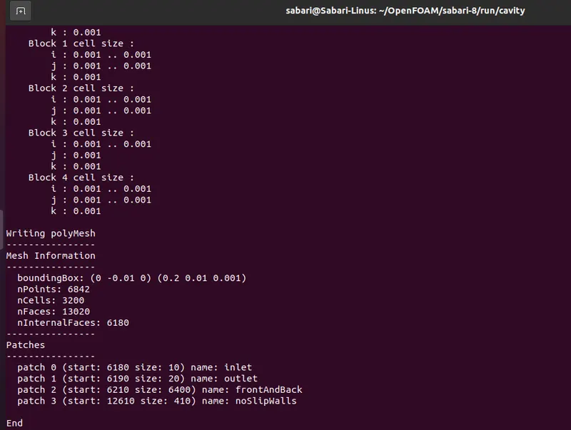
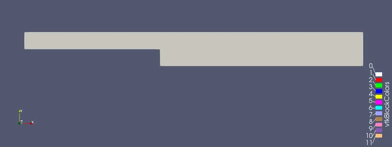
The mesh is successfully created with no errors and mesh is previewed in paraFoam to confirm if they are created as if we need them.

The geometry created is shown below
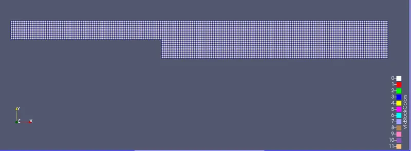
Generated mesh with GF 1 is shown below
Input files
Next initial conditions for the analysis need to be provided.
For providing the initial conditions of pressure, file "p" in the "0" folder is taken and modified as below.
/*--------------------------------*- C++ -*----------------------------------*\
  =========                 |
  \\      /  F ield         | OpenFOAM: The Open Source CFD Toolbox
   \\    /   O peration     | Website:  https://openfoam.org
    \\  /    A nd           | Version:  8
     \\/     M anipulation  |
\*---------------------------------------------------------------------------*/
FoamFile
{
    version     2.0;
    format      ascii;
    class       volScalarField;
    object      p;
}
// * * * * * * * * * * * * * * * * * * * * * * * * * * * * * * * * * * * * * //

dimensions      [0 2 -2 0 0 0 0];

internalField   uniform 0;

boundaryField
{
    inlet
    {
        type            zeroGradient;
    }

    outlet
    {
        type            fixedValue;
        value           uniform 0;
    }

    frontAndBack
    {
        type            empty;
    }
    noSlipWalls
    {
        type            zeroGradient;
    }
}

// ************************************************************************* //
In the "p" file, following the general intro of OpenFOAM and foamFile, the unit is mentioned in the standard format of the OpenFOAM. then the Boundary names are listed along with their boundary type and value. Inlet face and noslip wall faces are given with zerogradiennt, front and back walls re of type empty and outlet of fixed value 0 gauge pressure.
Following the pressure initial condition, velocity initial conditions are provided in the "U" file inside the "0" folder.
/*--------------------------------*- C++ -*----------------------------------*\
  =========                 |
  \\      /  F ield         | OpenFOAM: The Open Source CFD Toolbox
   \\    /   O peration     | Website:  https://openfoam.org
    \\  /    A nd           | Version:  8
     \\/     M anipulation  |
\*---------------------------------------------------------------------------*/
FoamFile
{
    version     2.0;
    format      ascii;
    class       volVectorField;
    object      U;
}
// * * * * * * * * * * * * * * * * * * * * * * * * * * * * * * * * * * * * * //

dimensions      [0 1 -1 0 0 0 0];

internalField   uniform (0 0 0);

boundaryField
{
    inlet
    {
        type            fixedValue;
        value           uniform (1 0 0);
    }

    outlet
    {
        type            zeroGradient;
    }

    frontAndBack
    {
        type            empty;
    }

    noSlipWalls
    {
        type            noSlip;
    }
}

// ************************************************************************* //
In the "U" file, following the general intro of OpenFOAM and foamFile, the unit is mentioned in the standard format of the OpenFOAM. then the Boundary names are listed along with their boundary type and value. Inlet face is given a fixed value 1m/s in the x-direction, outlet face is given with zerogradiennt, front and back walls re of type empty and for noslip wall faces, noSlip type is assigned.
As the simulation is transient, we need to provide the conditions of time & that is given in the "controldict" file inside the system folder.
/*--------------------------------*- C++ -*----------------------------------*\
  =========                 |
  \\      /  F ield         | OpenFOAM: The Open Source CFD Toolbox
   \\    /   O peration     | Website:  https://openfoam.org
    \\  /    A nd           | Version:  8
     \\/     M anipulation  |
\*---------------------------------------------------------------------------*/
FoamFile
{
    version     2.0;
    format      ascii;
    class       dictionary;
    location    "system";
    object      controlDict;
}
// * * * * * * * * * * * * * * * * * * * * * * * * * * * * * * * * * * * * * //

application     icoFoam;

startFrom       startTime; // latestTime for restarting in the middle

startTime       0;

stopAt          endTime;

endTime         2;

deltaT          0.0001;

writeControl    timeStep;

writeInterval   10;

purgeWrite      0;

writeFormat     ascii;

writePrecision  6;

writeCompression off;

timeFormat      general;

timePrecision   6;

runTimeModifiable true;


// ************************************************************************* //
In the "controldict" file, following the general intro of OpenFOAM and foamFile, Start time, end time, delta t & write interval are provided suitably
In the "transport properties" file inside the constant folder kinematic viscosity of the air is provided.
/*--------------------------------*- C++ -*----------------------------------*\
  =========                 |
  \\      /  F ield         | OpenFOAM: The Open Source CFD Toolbox
   \\    /   O peration     | Website:  https://openfoam.org
    \\  /    A nd           | Version:  8
     \\/     M anipulation  |
\*---------------------------------------------------------------------------*/
FoamFile
{
    version     2.0;
    format      ascii;
    class       dictionary;
    location    "constant";
    object      transportProperties;
}
// * * * * * * * * * * * * * * * * * * * * * * * * * * * * * * * * * * * * * //

nu              [0 2 -1 0 0 0 0] 0.0000148;


// ************************************************************************* //
Once all the input files are saved in respective folders, the simulation is started in the icoFoam application & post-processing is done in paraFoam.
Velocity Countour of Case 1
Case -2: Flow simulation with grading factor (i.e., GF = 0.2)
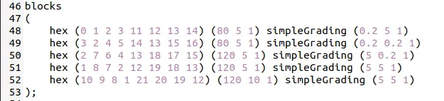
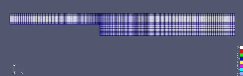
The grading factor can be changed in the blockMeshDict file. The following changes are made in the blockMeshDict to change the grading factor to 0.2. blockMesh command is used to create the mesh and its preview in paraFoam.
blockMeshDict file
Graded Mesh (GF=0.2)
All the input files in case 1 are the same here, except the mesh file & solved
Velocity Countour of Case 2
Desired Output - Velocity Profiles
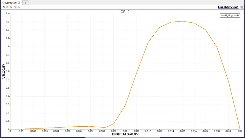
Velocity profile at 0.085 m from the inlet of the geometry for the case I
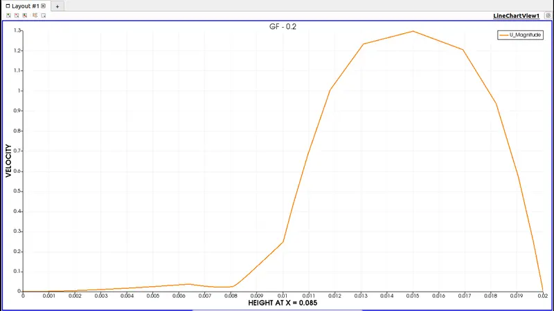
Velocity profile at 0.085 m from the inlet of the geometry for case II
Desired Output - why Grading/Growth factor is essential for meshing.
- On comparing the two graphs, we can see that the curve of case 2 (GF - 0.2) is smooth when compared with case 1 (GF - 1) particularly at the walls and near the step area.
- This is because the computational values near the walls and step area need more elements for capturing accurate solutions.
- Increase grading factor helps us capture the accurate solutions without an increase in the number of elements in the domain thus maintaining the total time taken to solve the problem.
- Boundary layer flow conditions are captured more clearly when the graded mesh is used.
- From the result videos, we can notice that the graded mesh case solves more accurately when compared with the ungraded mesh problem.
For these reasons, the graded mesh is preferred for solving CFD problems.