Week 8 - Simulating Cyclone separator with Discrete Phase Modelling
Simulating Cyclone separator with Discrete Phase Modelling
Aim:- To perform analysis on cyclone separator and calculate the separation efficiency and pressure drop.
Objective:-
- To write a few words about any four empirical models used to calculate the cyclone separator efficiency.
- To perform an analysis on a given cyclone separator model by varying the particle diameter from 1 μm to 5 μm and calculate the separation efficiency in each case. Discuss the results. [Use both the velocity's as 3m/sec.]
- To perform an analysis on a given cyclone separator model by varying the particle velocity from 1 m/sec to 5 m/sec and calculate the separation efficiency and pressure drop in each case. Discuss the results. [Use particle diameter size as 5 μm for all cases & keep flow velocity same as particle velocity]
------------------------------------------------------------------------------------------------------------------------------------------------------------------
1. To write a few words about any four empirical models used to calculate the cyclone separator efficiency.
Cyclones separator are devices that employ a centrifugal force generated by a spinning gas stream to separate partices from the carrier gas. These are basically centrifugal separators. They simply transform the inertia force of gas particle to a centrifugal force by means of a vortex generated in the cyclone body. The particle laden gas enters tangentially at the upper part & passes through the body describing the vortex. Particles are driven to the walls by centrifugal forces, losing its momentum & falling down to the cyclone leg.
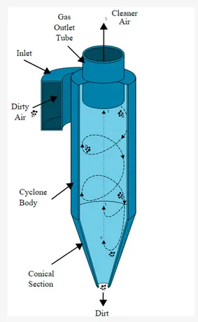
Four empirical models used to calculate the cyclone separator efficiency-
a) lozia & leith model:
lozia & leith logistic model is a modified version of Barth model, which is developed based on force balance. The model assumes that particle carried by the vortex endures the influence of two forces: a centrifugal force,Z & a flow resistance, W.The collection efficiency E of particle diameter dpi can be calculated from
E=1/(1+(dpc/dpi)^beta)
b) li & wang model:
The li & wang model include particle bounce or re-entrainment & turbulent diffusion at the cyclone wall. A 2D analytial expression of particle distribution in the cyclone is obtained. The resultant expression of the collection efficiency for particle of any size is given as
E= 1-exp{-lambda*theta(1)}, where theta1= (2*pie(S+L))/α">α
c) koch & licht model:
koch & licht model recognized the inherently turbulent nature of cyclones & the distribution of gas residence times within the cyclone. koch & licht described particle motion in the entry & collection regions with additional following assumptions:
- The tangential velocity of a particle is equal to the tangential velocity of gas flow, i.e there is no slip in the tangential direction between the particle & gas.
- The tangential velocity is related to the radius of cyclone by uRn=constant.
A force balance & an equation on the particles collection yield the grade efficiency E
E=1-exp*{-2[((G*tau*Q)/(D^3))*(n+1)]^0.5/(n+1)}
d) lapple model:
lapple model was developed based on force balance without considering the flow resistance. Lapple assumed that a particle entering the cyclone is evenly distributed across the inlet opening. The particle that travels from inlet half width to the wall in cyclone is collected with 50% efficiency.
The efficiency of collection of any size of particle is given by
E=1/(1+(dpc/dpi)^2), where dpi is particle diameter & dpc is cut diameter.
-----------------------------------------------------------------------------------------------------------------------------------------------------------------------------------------
Simulation:
Geometry Setup:
As we import cyclone separator geometry, we need to carry out analysis on fluid volume, so extract fluid volume.
Preapare->volume extract->edges
Mesh Generation:
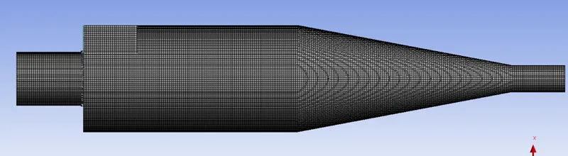
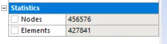
As in Ansys 2020 R2 cut cell mesh option is not available so we choose cartesian mesh method.
Name selection: name one inlet (in axial direction), outlet 1 at top & outlet 2 at bottom.
Select cutcell meshing for the best results.
Mesh element size is 5mm.
Fluent Setup:
Setting physics:
Select k-epsilon, RNG, with swirl dominated flow turbulent model.
Solver- pressure based as Mach number is less than 3.
choose steady state-solver, enable gravity in y-axis -9.81 m/s^2.
Material selection:
for gas- air
for solid particles- Anthracite
Material properties:
For air: density= 1.22 kg/m^3
viscosity= 0.0000181 kg/m.s
For anthracite: density= 1506 kg/m^3
Boundary condition setup:
for inlet:
velocity= 1,3,5 m/s
Temp.= 300K
In DPM:
Inlet & wall- reflect
Outlet:
pressure= 0 Pa
In DPM:
outlet (top)- escape
outlet (bottom)- trap
To enable interaction between gas & solid particles, turn on DPM.
Click on interaction with continuos phase.
select update DPM sources every flow iterations.
select contour plots for DPM variables.
select maximum number of steps 50,000 & step length factor 5.
Now select Injections->create->particle type->inert->material(anthracite)->injection type(surface injections)->surface release(inlet)
Point properties: x-velocity= 3m/s, diameter= 5 microns, total flow rate= 1e-20 kg/s.
Solution:
Methods
for turbulent kinetic energy-> 1st order upwind interpolation scheme.
for turbulent dissipation rate-> 1st order upwind interpolation scheme.
Controls: pressure of particle 0.1, momentum of particles 0.3
Solving: standard initialization->options->compute from inlet->initialize & calculate.
After calculations, check DPM data from console & export->particle history data from injection0 folder for CFD post.
CFD Results:
Import particle data.
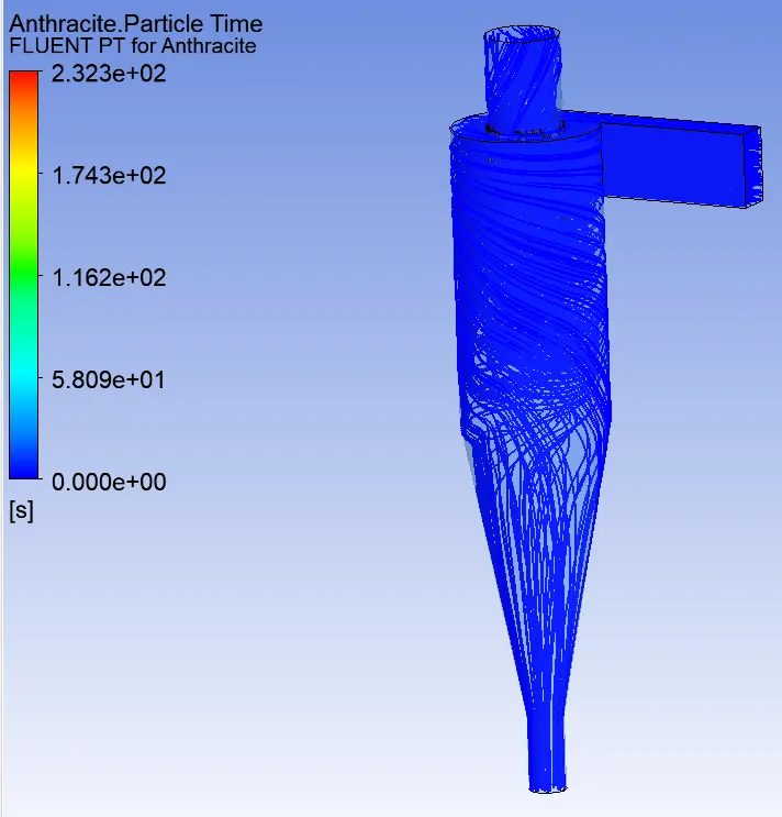
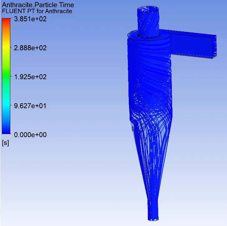
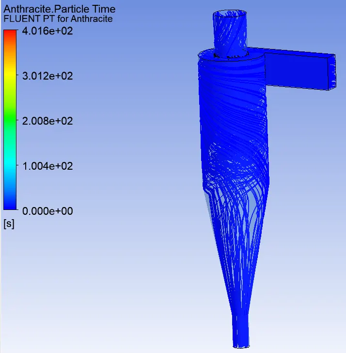
double click on Fluent PT for Anthracite->color(anthracite particle time)->apply.
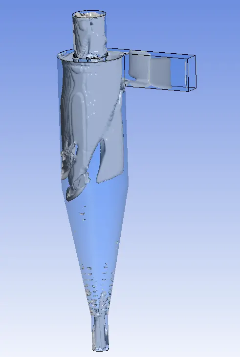
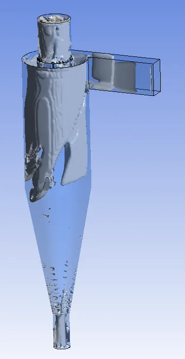
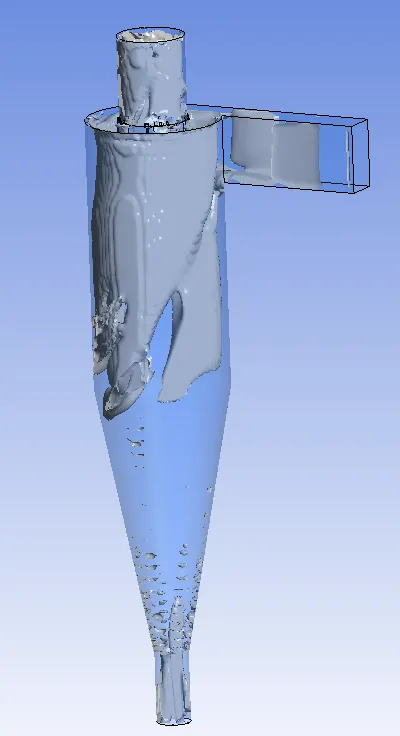
Enable the vortex core region.
Create an animation of particle tracking.
calculate various properties like mass flow rate, pressure, velocity.
Plots & results:
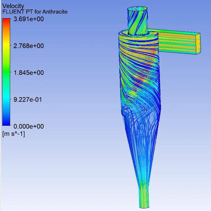
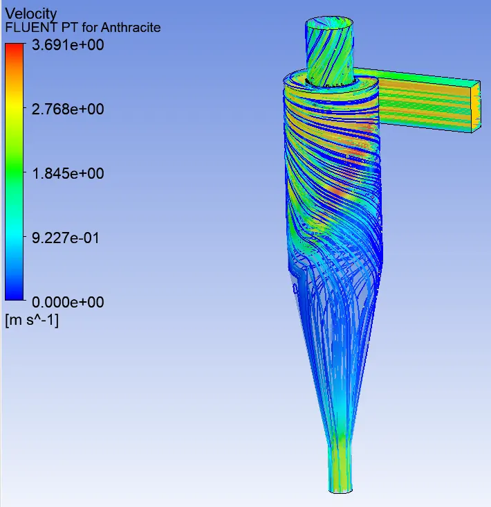
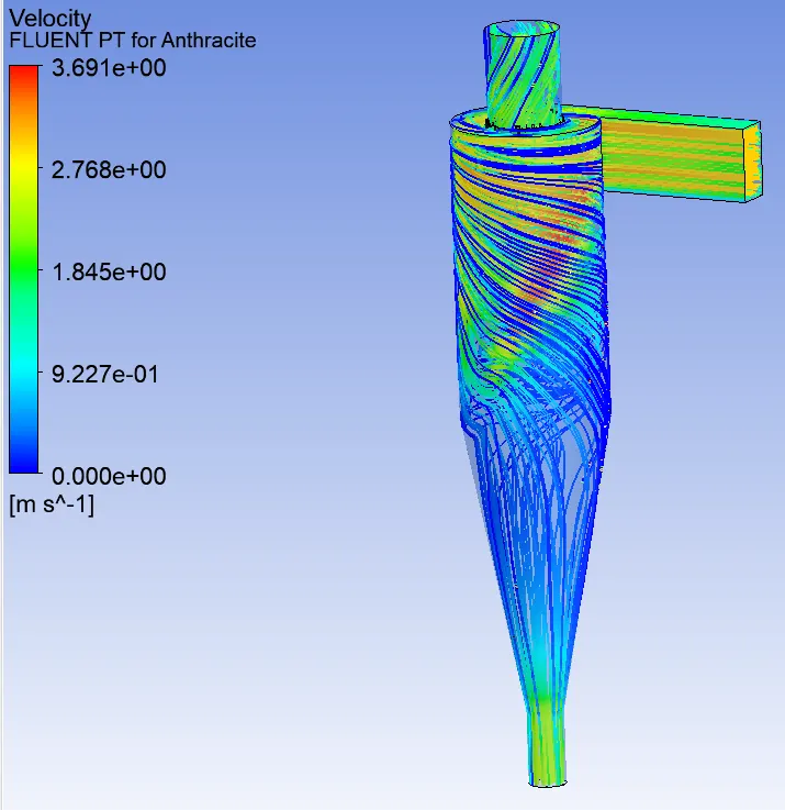
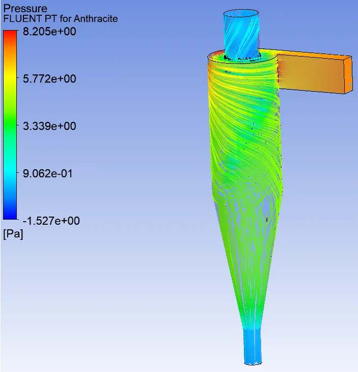
case 1- For the particle diameter from 1,3 & 5 μm respectively & velocity of gas & particle is constant 3 m/s.
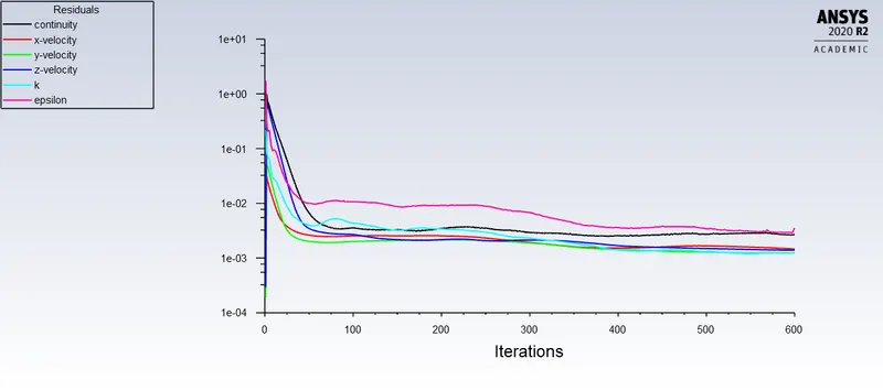
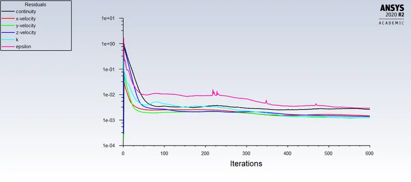
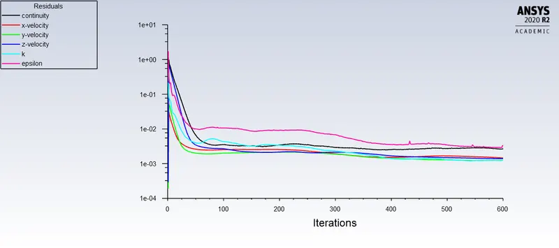
Residual plot:
Anthracite particle time plot:
Vortex core region:
Velocity tracking of particles:
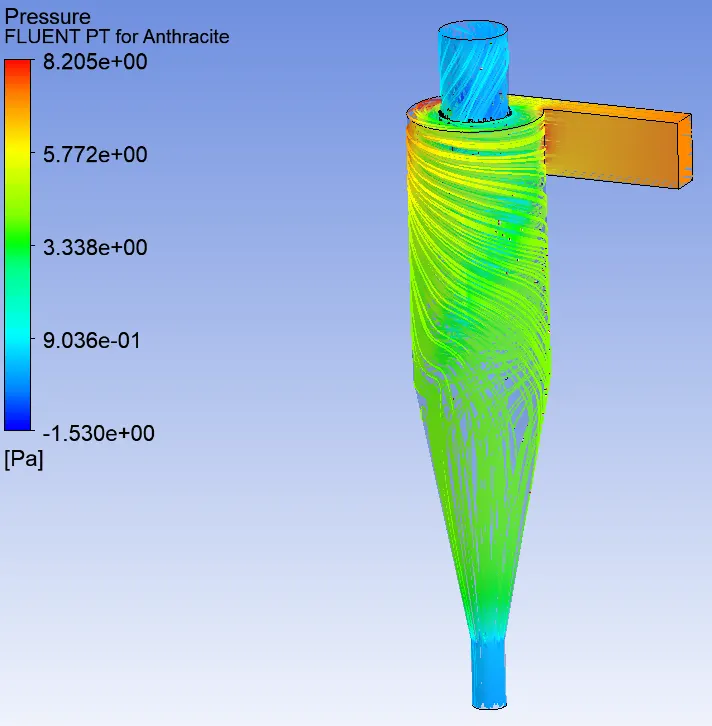
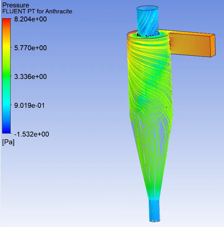
Pressure plots:
Efficiency & mass flow rate:
At a velocity of particle & gas is constant 3 m/s
For particle size 1 micron
Mass flow rate at accept port=-0.0126078 kg/s
Mass flow rate at reject/trash port=-0.0057678 kg/s
Particle tracked=378; particle escaped=200; trapped=133, incomplete=45
E=Number of particle trapped/number of particles tracked= 133/378=35.19%
For particle size 3 micron
Mass flow rate at accept port=-0.0126076 kg/s
Mass flow rate at reject/trash port=-0.00576779 kg/s
Particle tracked=378; particle escaped=203; trapped=137, incomplete=38
E=Number of particle trapped/number of particles tracked= 137/378=36.24%
For particle size 5 micron
Mass flow rate at accept port= -0.020851 kg/s
Mass flow rate at reject/trash port= -0.00977679 kg/s
Particle tracked=378; particle escaped=185; trapped=146, incomplete=47
E=Number of particle trapped/number of particles tracked= 146/378=38.62%
- As the particle size increases, the efficiency of cyclone separator also increases.
- The mass flow rate is negative, means mass flows out of the separator.
-----------------------------------------------------------------------------------------------------------------------------------
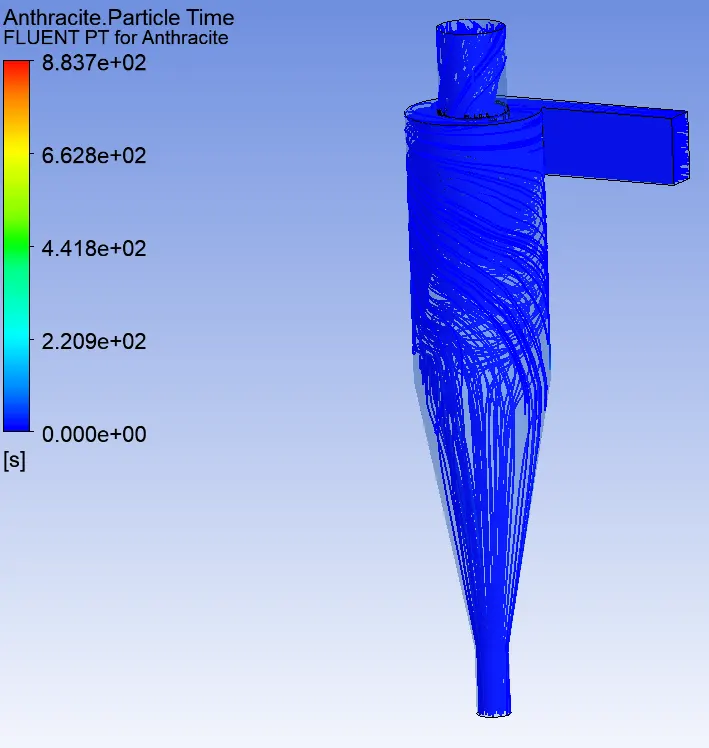
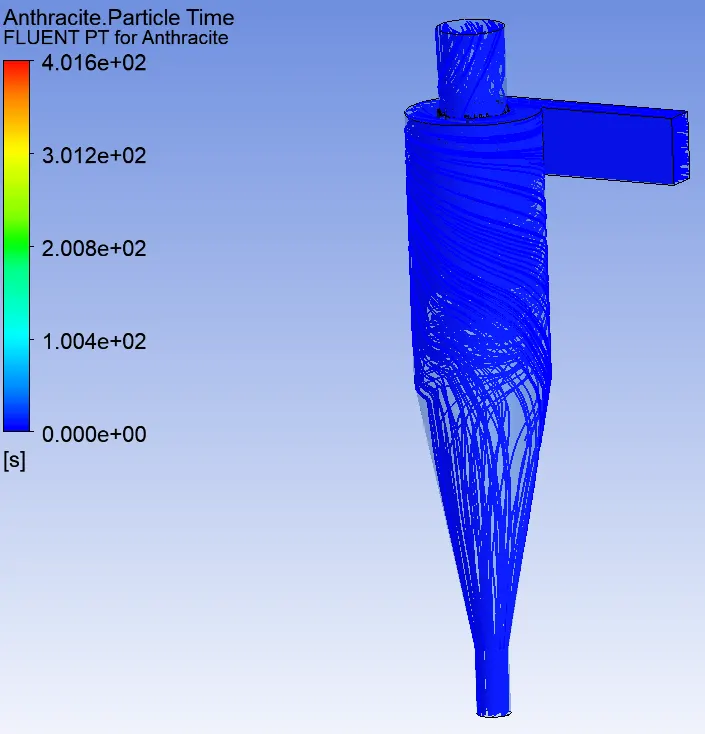
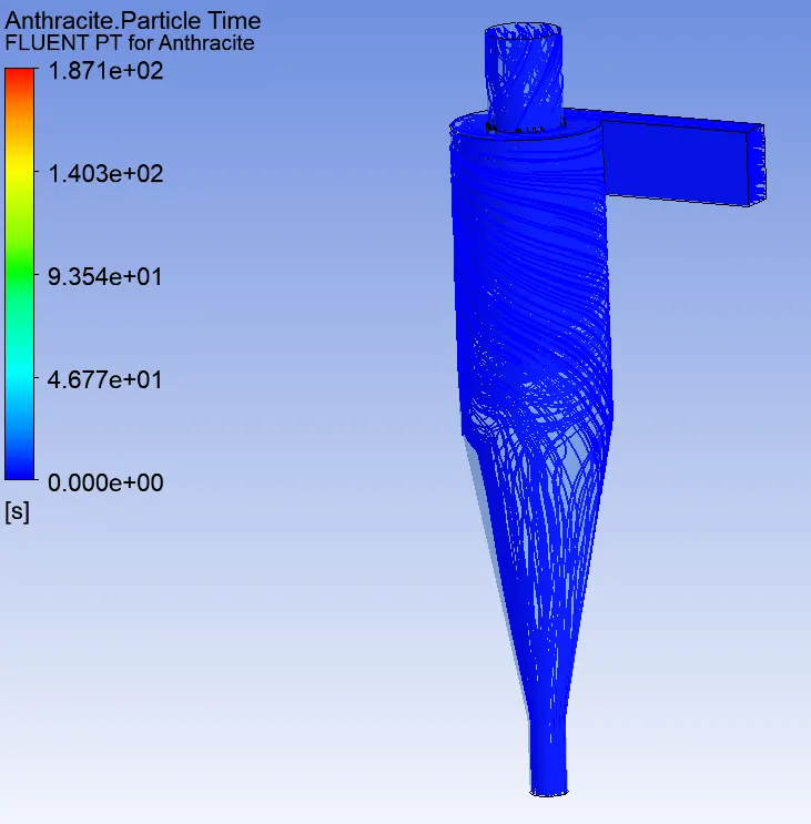
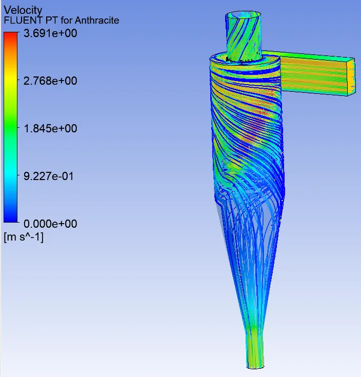
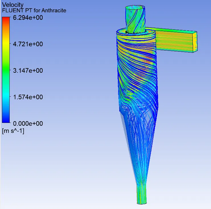
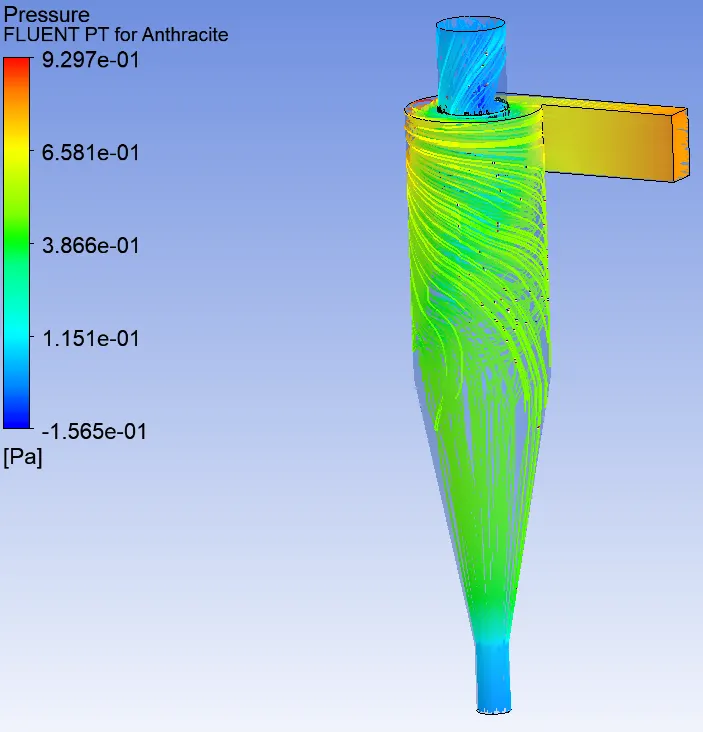
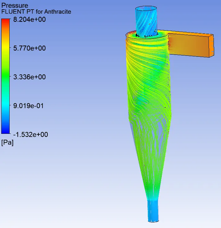
case 1- For the particle & gas velocities are 1,3 & 5 m/s respectively, particle size is constant 5 μm.
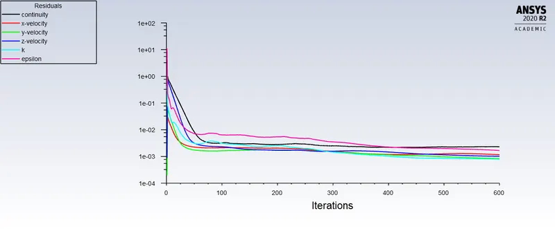
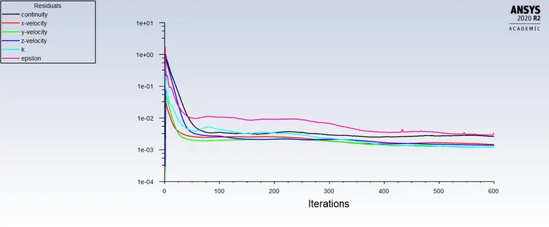
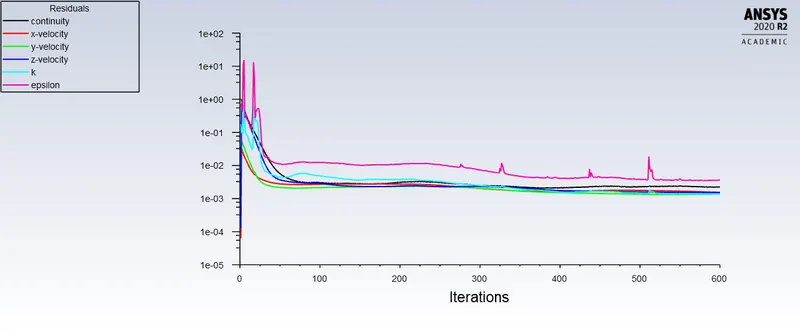
Residual plot:
Anthracite particle time plot:
Vortex core region:
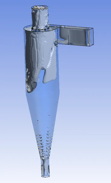
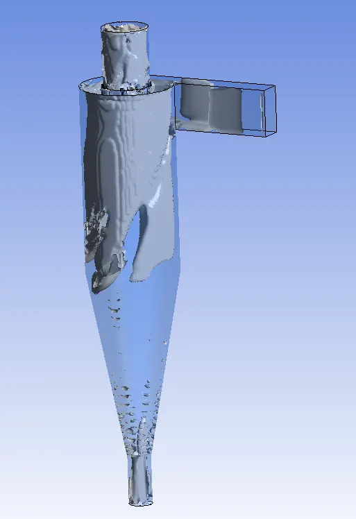
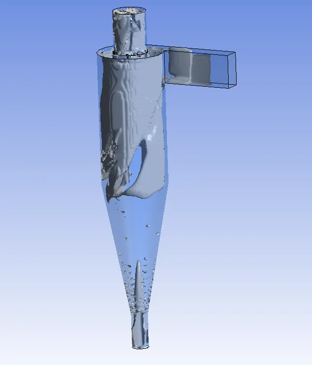
Velocity tracking of particles:
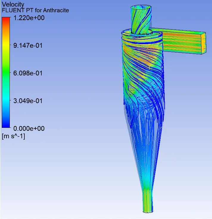
Pressure plots:
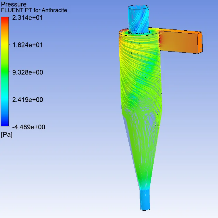
Efficiency & mass flow rate:
At a particle size constant 5 microns &
For particle & gas velocity 1 m/s
Mass flow rate at accept port= -0.00431663 kg/s
Mass flow rate at reject/trash port= -0.00180832 kg/s
Particle tracked=378; particle escaped=183; trapped=136, incomplete=59
E=Number of particle trapped/number of particles tracked= 136/378=35.98%
For particle & gas velocity 3 m/s
Mass flow rate at accept port= -0.0126075 kg/s
Mass flow rate at reject/trash port= -0.00576771 kg/s
Particle tracked=378; particle escaped=185; trapped=149, incomplete=44
E=Number of particle trapped/number of particles tracked= 149/378=39.42%
For particle & gas velocity 5 m/s
Mass flow rate at accept port= -0.020851 kg/s
Mass flow rate at reject/trash port= -0.00977679 kg/s
Particle tracked=378; particle escaped=157; trapped=180, incomplete=41
E=Number of particle trapped/number of particles tracked= 180/378=47.62%
- As the velocity of gas & particles increases for the same size of particle, the efficiency of cyclone separator also increases.
- The mass flow rate is negative, means mass flows out of the separator.
-----------------------------------------------------------------------------------------------------------------------------------
Conclusion:
- As the velocity of gas & particles increases for the same size of the particle, the efficiency of cyclone separator & pressure drop also increases due to inertia.
- As the particle size increases the efficiency of cyclone separator & pressure drop also increases.
Animation:
- Sam24fatehHello, I would like to know how did you keep the number of particles trapped (injected) 378 please?