Week 8 - Simulating Cyclone separator with Discrete Phase Modelling
OBJECTIVE:
- To write a few words about any four empirical models used to calculate the cyclone separator efficiency.
- To perform an analysis on a given cyclone separator model by varying the particle diameter from 1 μm to 5 μm and calculate the separation efficiency in each case. Discuss the results. [Use both the velocity's as 3m/sec.].
- To perform an analysis on a given cyclone separator model by varying the particle velocity from 1 m/sec to 5 m/sec and calculate the separation efficiency and pressure drop in each case. Discuss the results. [Use particle diameter size as 5 μm for all cases & keep flow velocity same as particle velocity].
CYCLONE SEPARATOR:
- (Gas)Cyclone separator is widely used in industries to separate dust from gas of for product recovery because of its geometrical simplicity, economy in power and flexibility. These devices employ a centrifugal force generated by a spinning gas stream to separate particles rom the carrier gas. Because of its excellent features in design, low capital cost and also a maintenance free operation make them ideal for use as precleaners for more expensive final control devices such as bag houses or electrostatic precepitators. Cyclone collection efficiencies can reach 99% for particles bigger than 5µm and can be operated at very high dust loading.Cyclones are used for the removal of large paricles for both air pollution control and process use. CFD has a great potential to predict the flow field characteristics and particle trajectories inside the cyclone.
- Many different types of cyclone separators have been built but the reverse flow cyclone with tangential inlet. The below shows the most often type used for industrial gas cleaning.
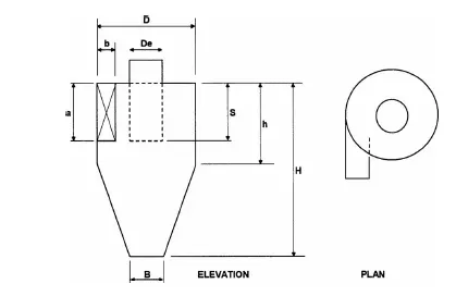
Tangential cyclone configuration.
Empirical models used to calculate the cyclone separator efficiency.
- Iozia and Leith Model.
It is a modified version of barth model, which is developed based on force balance. This model assumes that a particle is carried by the vortex endures the influence of two forces, which are the centrifugal force (Z) and a flow resistance. The collection efficiency (╖i ) of particle with diameter dpi can be calculated from;
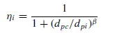
ß is an expression for slope parameter derived based on the statistical analysis of experimental data of a cyclone with a respective D.

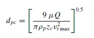
dpc is the 50% cut size given by barth.
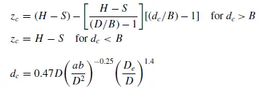
zc - Core length and dc - Core diameter
2. Li and Wanng Model.
The Li and Wang model includes particle bounce or reentrainment and turbulent diffusion at the cyclone wall. Li and Wang model was developed based on the following assumptions.
- The radial particle velocity and he radial concentration profile are not constant for uncollected particles with in the cyclone.
- Boundary conditions with the consideration of turbulent diffusion coefficient and particle bounce reentrainment on the cyclone wall are;
c = c0 , at θ = 0.
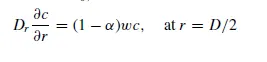
- The tangential velocity is related to the radius of cyclone by: uRn = constant.
The concentration distribution in the cyclone is given as;
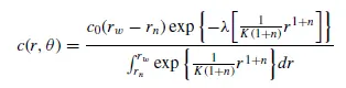
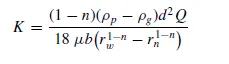
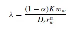
The collection efficiency for particle of any size is given as;
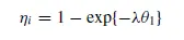
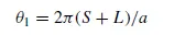
3. Koch and Licht Model.
Koch and Licht described particle motion in the entry and collection regions with the additional following assumptions.
- The tangential velocity of particle is equal to the tangential velocity of the gas flow,i.e; there is no slip in the tangential direction between the particle and the gas.
- The tangential velocity is related to the radius of cyclone by uRn = constant.


G- factor related to the configuration of the cyclone
n- Related to the vortex and Ⴀ -Relaxation term.
3. Lapple Model.
It is developed based on the force balance without considering the flow resistance. Lapple assumed that a particle entering the cyclone is evenly distributed across the inlet opening. The particle that travels from inlet half width to the wall in the cyclone is collected with 50% efficiency. The semi empirical relationship developed by Lapple to calculate a 50% cut diameter, dpc is;
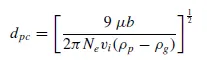
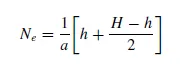
where Ne - No of revolutions.
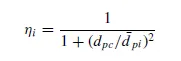
Efficiency of the collection of any size of particle is given by;
Case:1-Changing particle diameter from 1 micrometer to 5 micrometer, with velocity as 3 m/s
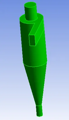
GEOMETRY SETUP.
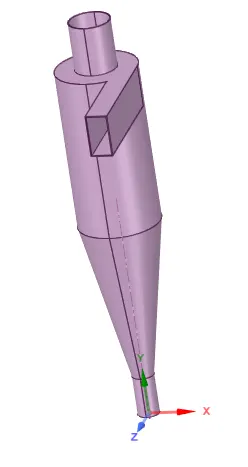
- Starting from the fluent(fluid flow) module and import the step file of cyclone separator.
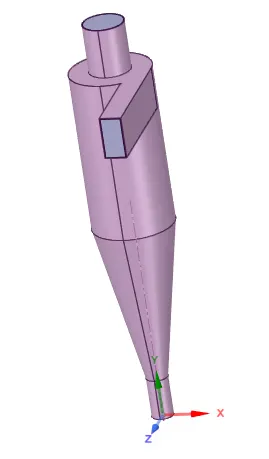
- Edit the geometry of cyclone separator in Ansys spaceclaim.
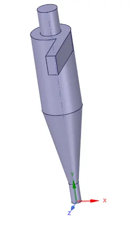
- Fluid volume is extracted from the geometry by using the Prepare → Volume extract option.
- Hide the previous geometry and supress physics, since we are inerested only fluid volume and not the external surface.
MESHING.
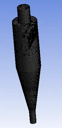
- After editting the geometry and extracting the fluid volume, a suitable mesh has to be provide.
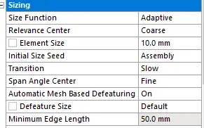
- Choose generate mesh to generate a base line mesh and then a suitable element size has to be provided for numerical simulation.
- Element size = 10mm.
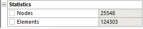
- No of elements = 124303.
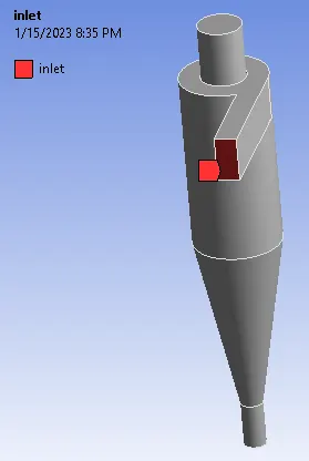
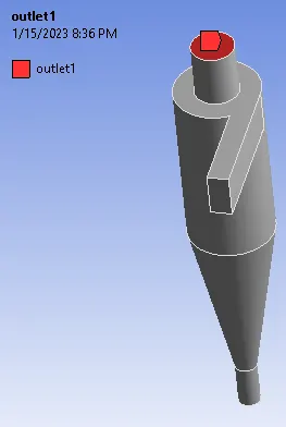
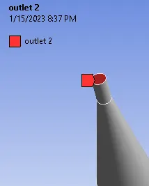
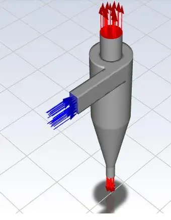
- The next step is to provide "Named selection", Face selection tool is selected and provide the inlet , outlet has shown below.
SET UP.
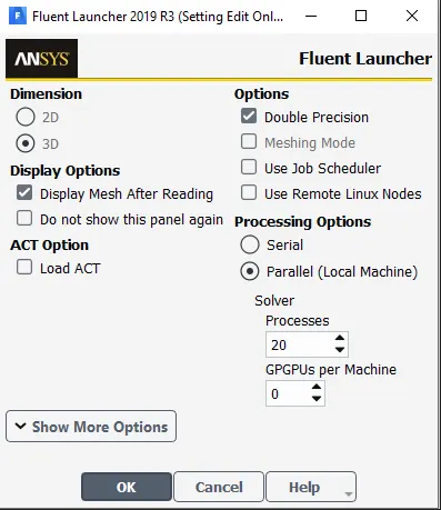
General Conditions.
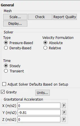
- As it is in the x-y plane, the acceleration due to gravity needs to be turned on. we can see that the acceleration due to gravity acts in upward direction. so the g valuue is assigned as -9.81 in the positive y axis.
- Solver type - Pressure based
- Steady state analysis is done and the velocity formulation is normal to the boundary and absolute.
Turbulence Modelling:
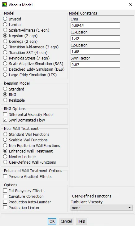
- K-epsilon(2 eqn) model with RNG and swirl dominated flow is selected and the wall functions are enhanced wall treatment, since the temperature is not involved hence the energy is turned off.

DPM(Discrete Phase Modelling).
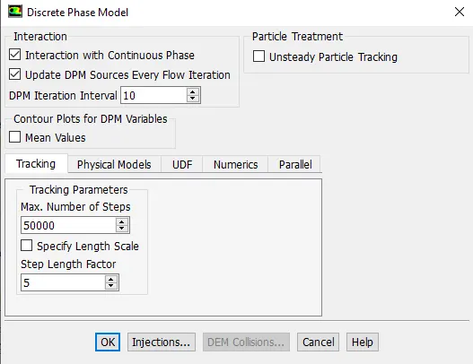
- Discrete Phase Modelling (DPM) is a method in which the flow of the discrete phase with a continuous flow is modeled. DPM is used to track individual particles through the continuum fluid.
- The Lagrangian discrete phase model follows the Euler Lagrange approach.
- The fluid phase is treated as a continuum by solving the Navier Stokes equation, while the dispersed phase is solved by tracking a large number of particle, bubble, or droplet through the calculated flow field.
- The dispersed phase can exchange momentum, mass, and energy with the fluid phase.
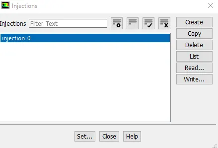
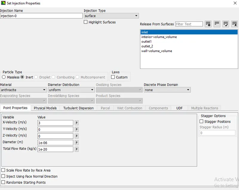
Boundary conditions.
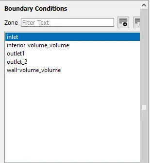
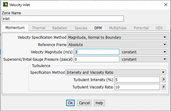
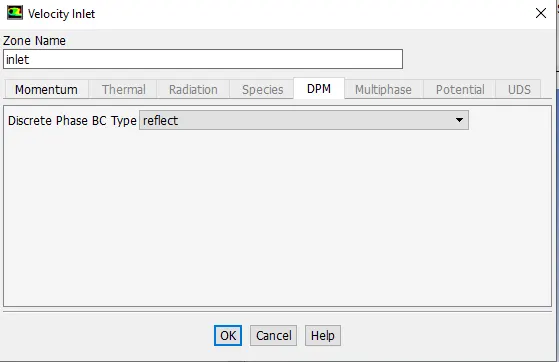
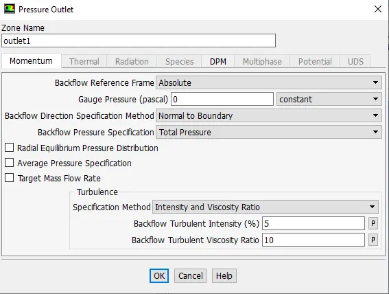
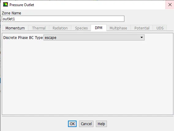
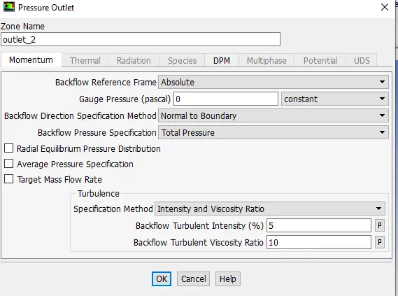
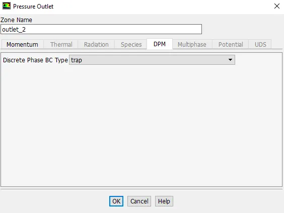
Initialization: Standard initialization is done with flow compute from inlets.
RESULTS.
PART:1- Varying the particle diameter from 1 to 5µm, with velocity 3m/s.
- Dia of particle equal to 1µm.
Residual.
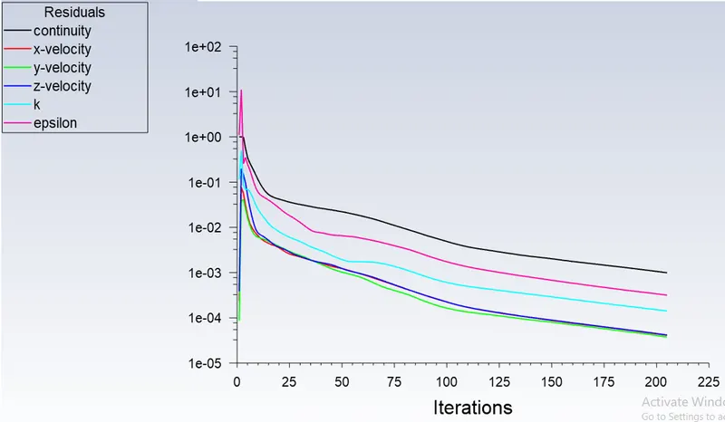
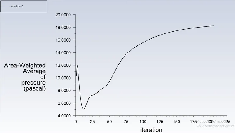
Area weighted average of pressure (pa) at inlet:-
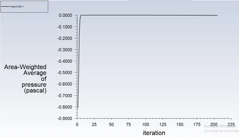
Area weighted average of pressure (pa) at Outlet-1:-
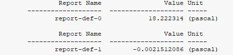
Post processing - Results.
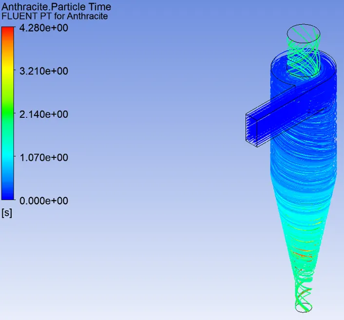
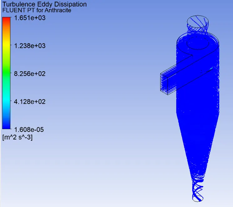
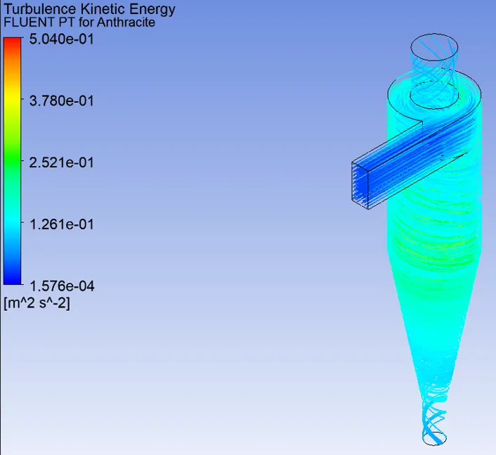
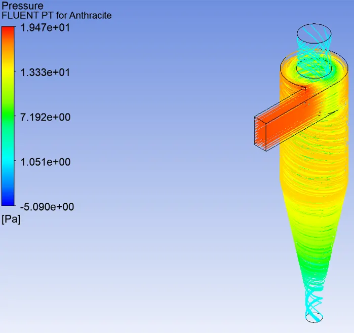

- Separation Efficiency = ((No of particles trapped)/(No of particles tracked))* 100
= (40/124)*100 = 32.25%.
- Dia of particle equal to 2µm.
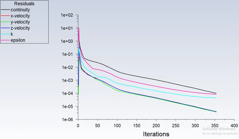
Residual.
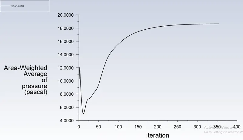
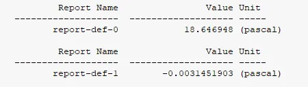
Area weighted average of pressure (pa) at inlet:-
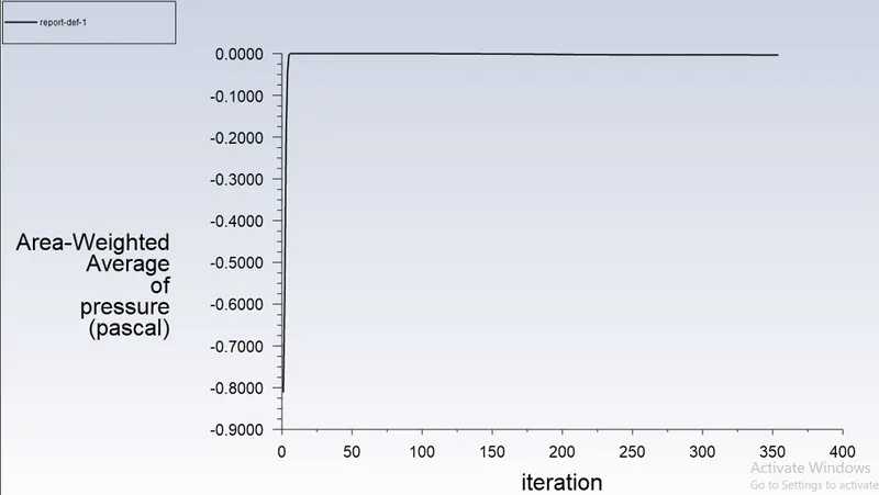
Area weighted average of pressure (pa) at Outlet-1:-
Post processing - Results.
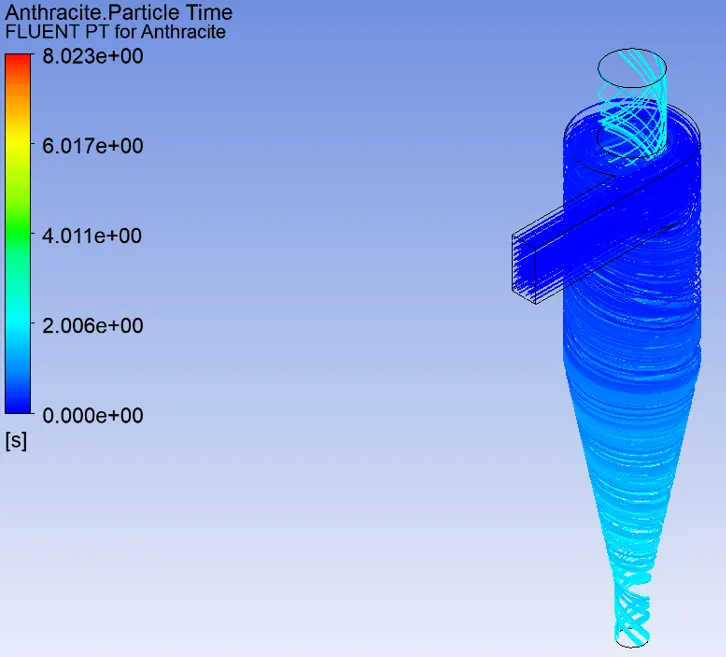
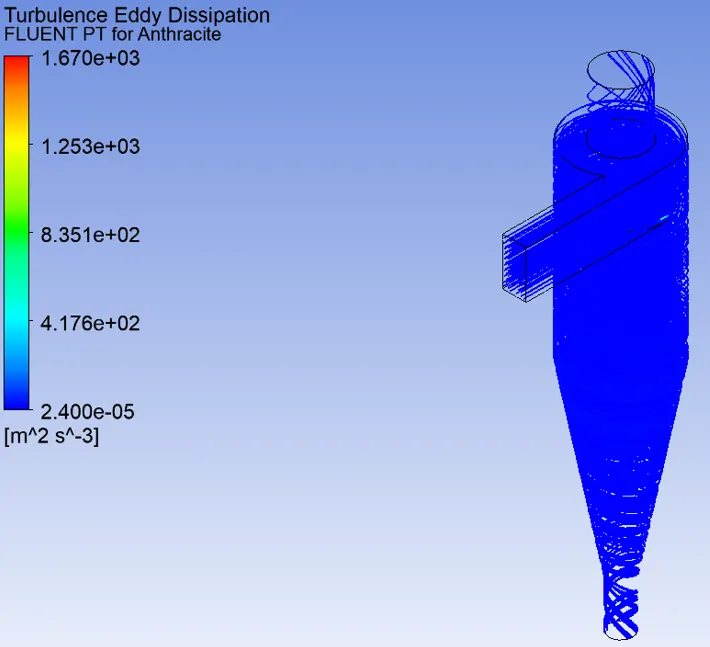
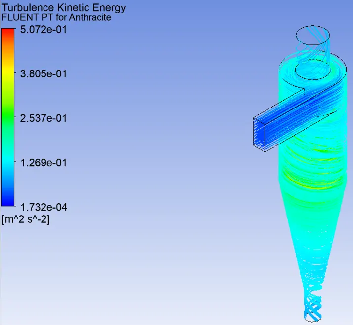
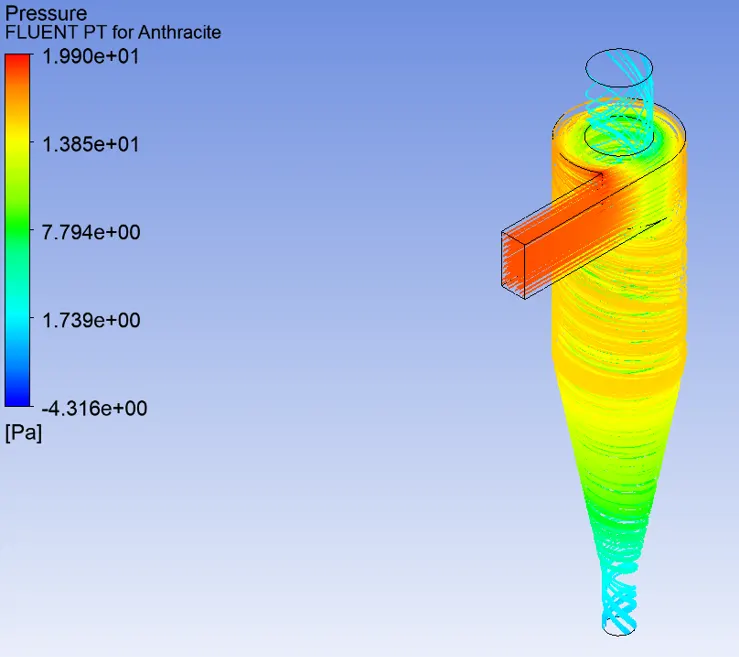

- Separation Efficiency = ((No of particles trapped)/(No of particles tracked))* 100
= (98/124)*100 = 79.03%.
- Dia of particle equal to 3µm.
Residual.
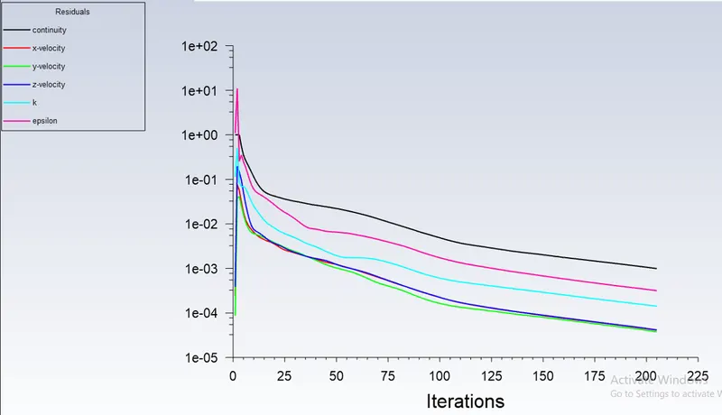
Area weighted average of pressure (pa) at inlet:-
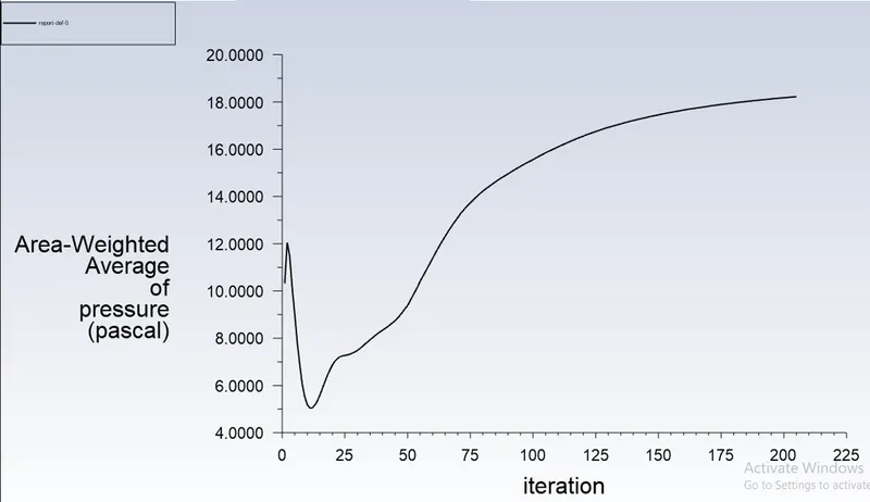
Area weighted average of pressure (pa) at Outlet-1:-
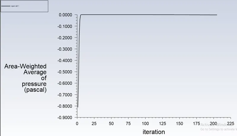
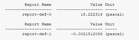
Post processing - Results.
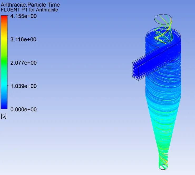
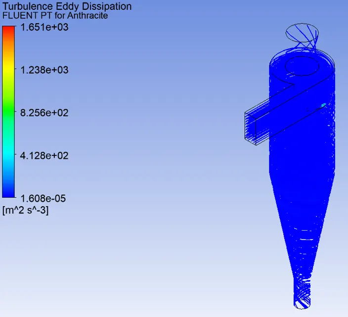
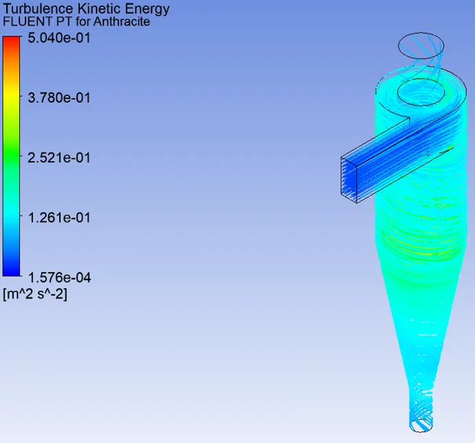
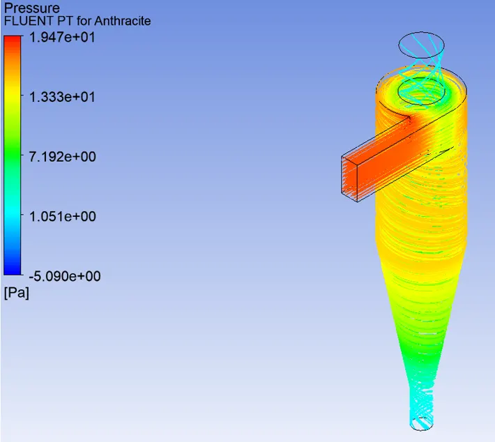

- Separation Efficiency = ((No of particles trapped)/(No of particles tracked))* 100
= (110/124)*100 = 88.71%.
- Dia of particle equal to 4µm.
Residual.
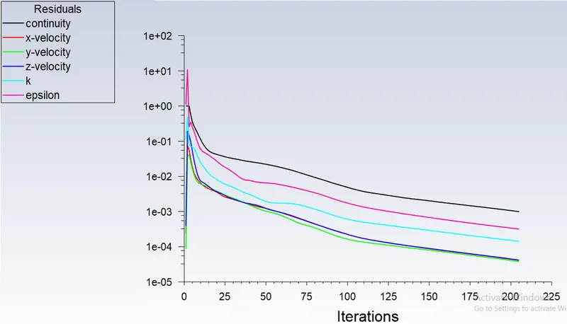
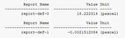
Area weighted average of pressure (pa) at inlet:-
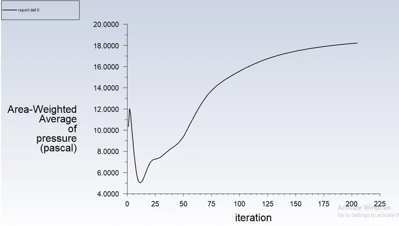
Area weighted average of pressure (pa) at Outlet-1:-
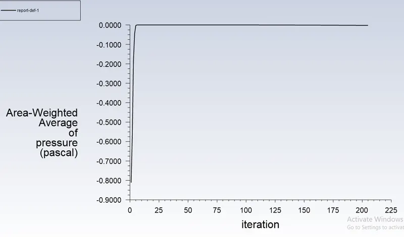
Post processing - Results.
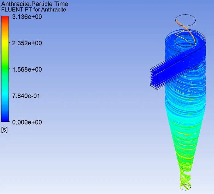
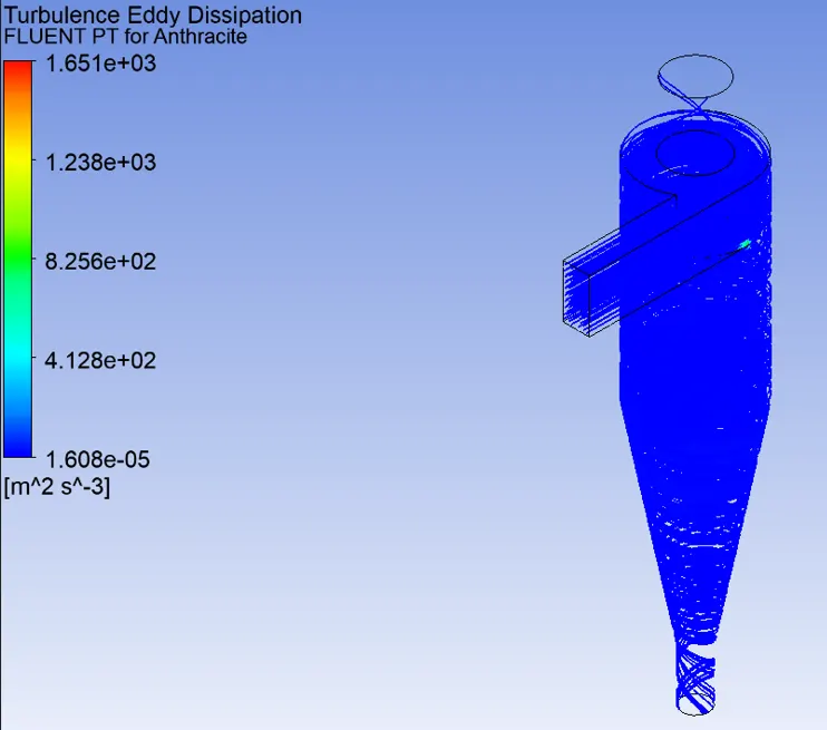
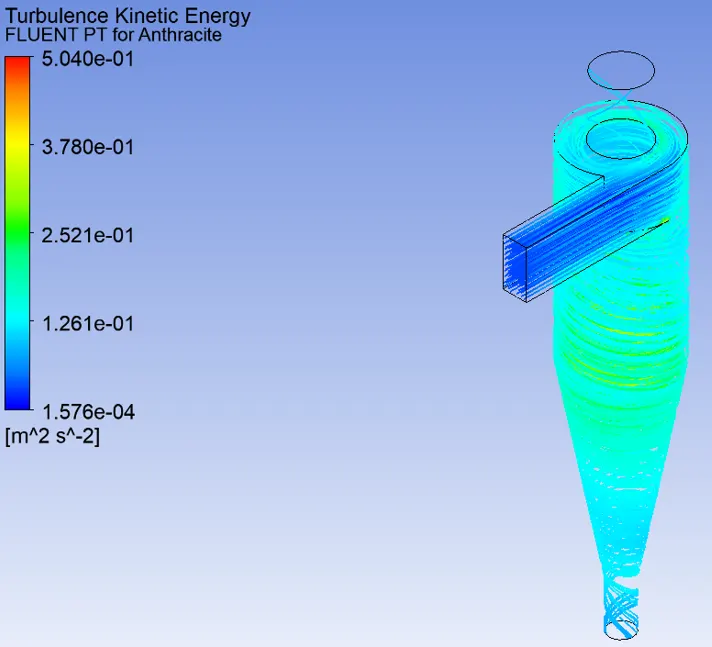
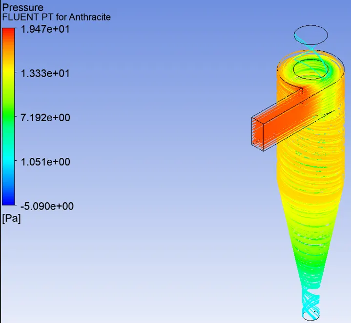

- Separation Efficiency = ((No of particles trapped)/(No of particles tracked))* 100
= (120/124)*100 = 96.77%.
- Dia of particle equal to 5µm.
Residual.
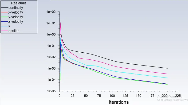
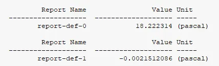
Area weighted average of pressure (pa) at inlet:-
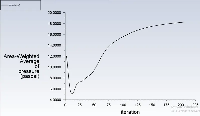
Area weighted average of pressure (pa) at Outlet-1:-
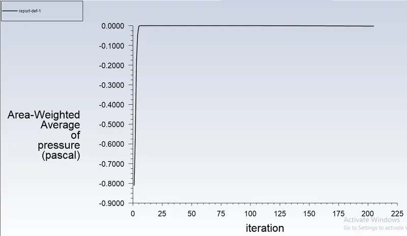
Post processing - Results.
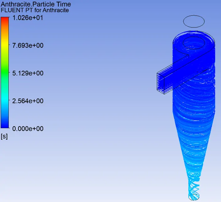
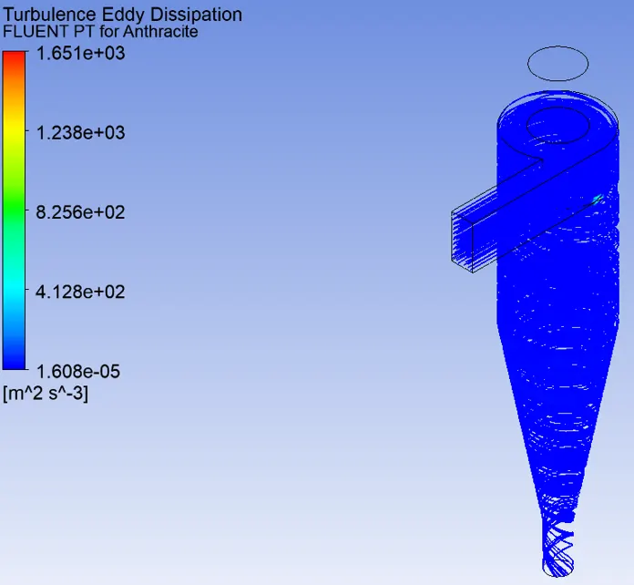
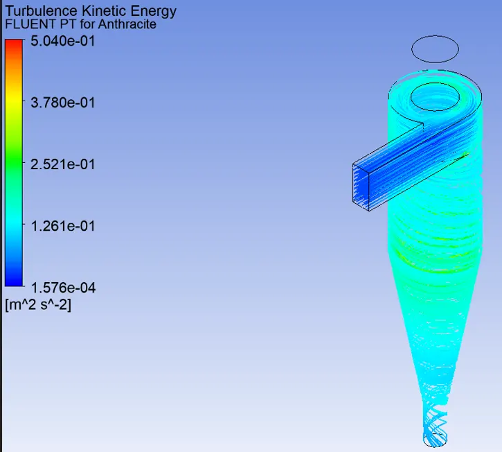
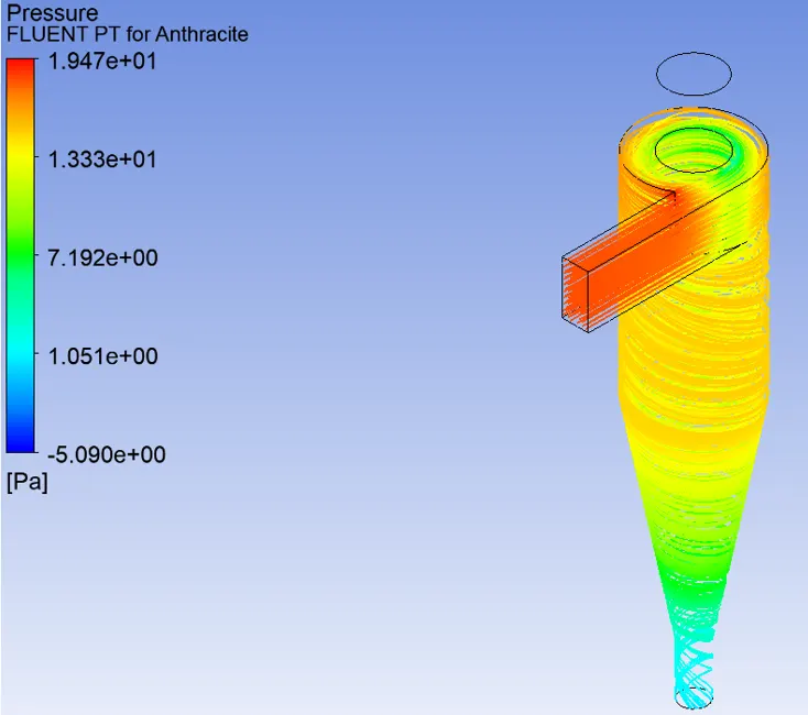

- Separation Efficiency = ((No of particles trapped)/(No of particles tracked))* 100
= (123/124)*100 = 99.20%.
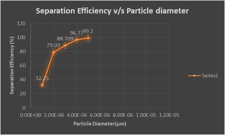
Plot showing the variation of separation efficiency of cyclone separator with varying particle diameter.
PART:1- Varying the inlet velocity from 1m/s to 5m/s for a fixed particle diametr of 5µm.
- Inlet veolcity-1m/s, for a particle size of 5µm.
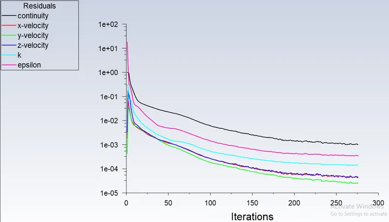
Residual.
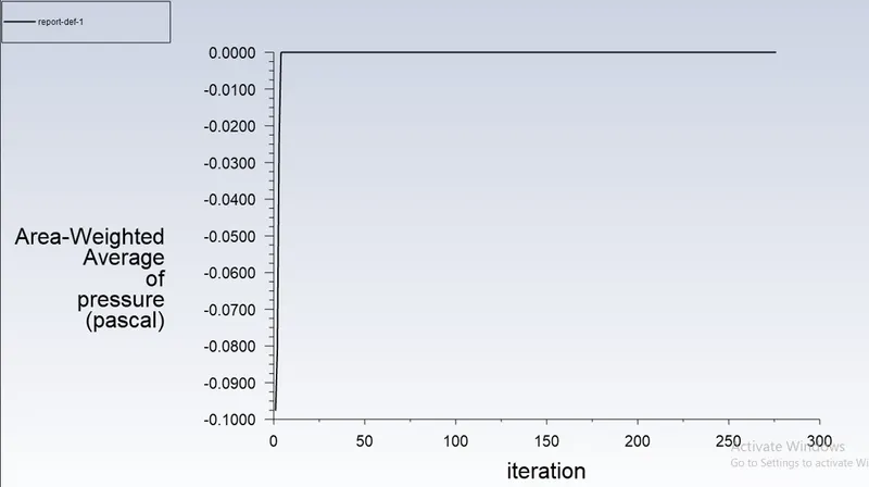
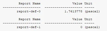
Area weighted average of pressure (pa) at inlet:-
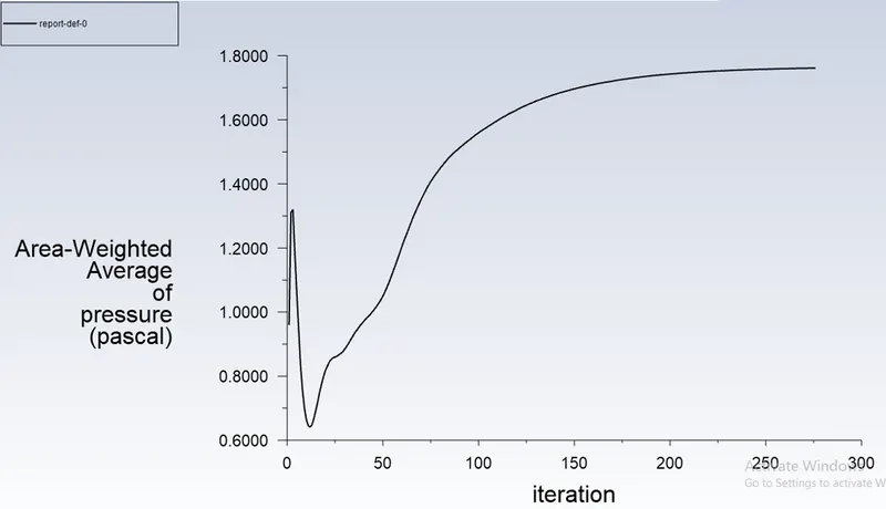
Area weighted average of pressure (pa) at Outlet-1:-
Post processing - Results.
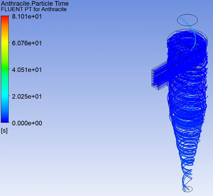
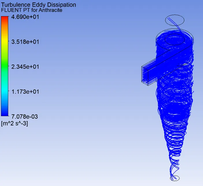
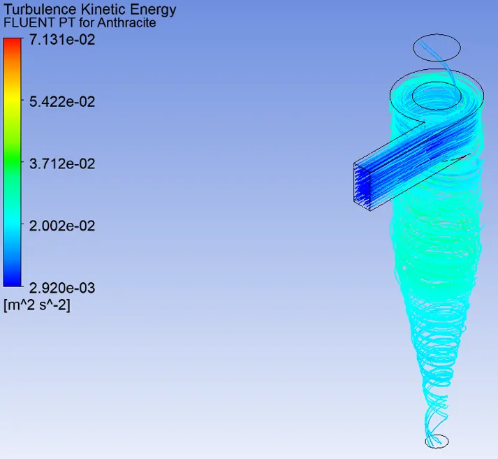
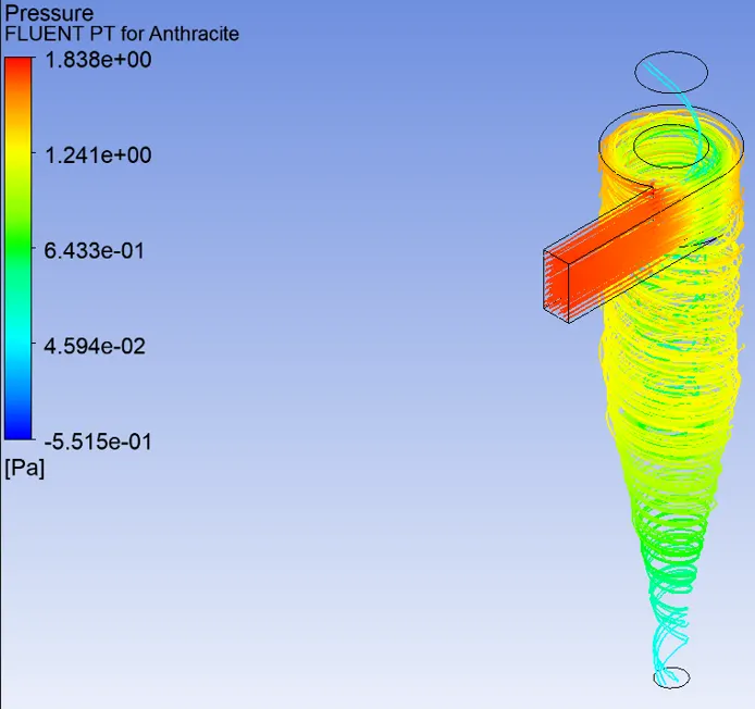

- Separation Efficiency = ((No of particles trapped)/(No of particles tracked))* 100
= (6/124)*100 = 4.83%.
- Inlet veolcity-2m/s, for a particle size of 5µm.
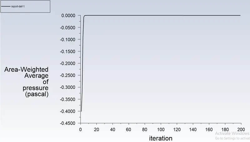
Residual.
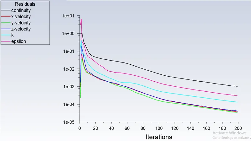
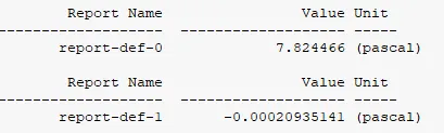
Area weighted average of pressure (pa) at inlet:-
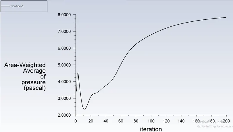
Area weighted average of pressure (pa) at Outlet-1:-
Post processing - Results.
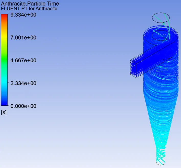
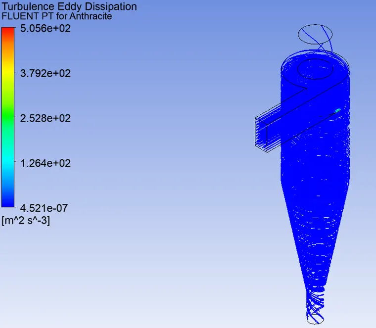
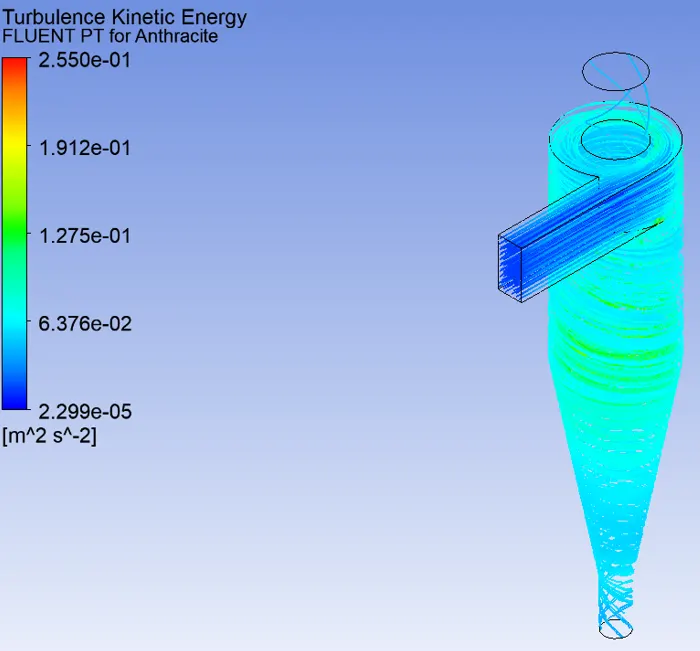
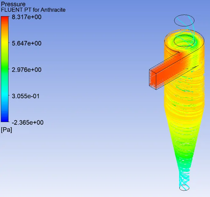

- Separation Efficiency = ((No of particles trapped)/(No of particles tracked))* 100
= (21/124)*100 = 16.93%.
- Inlet veolcity-3m/s, for a particle size of 5µm.
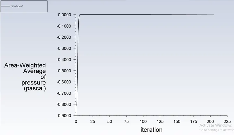
Residual.
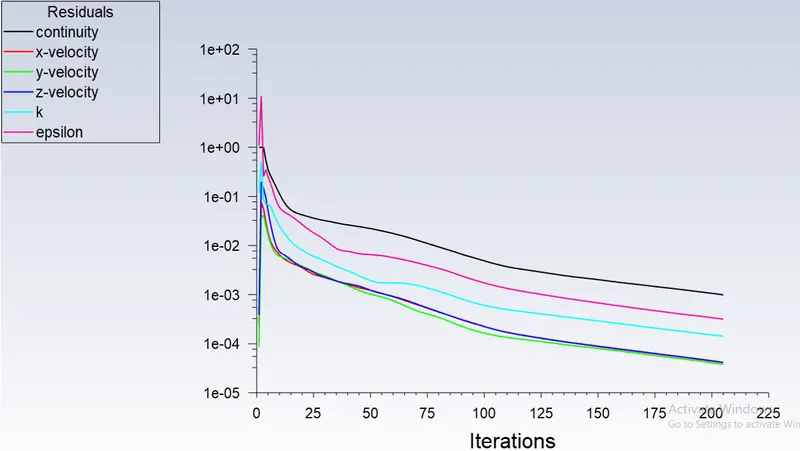
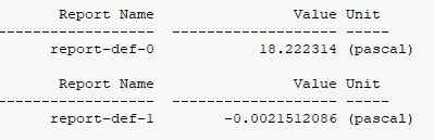
Area weighted average of pressure (pa) at inlet:-
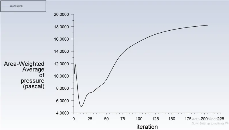
Area weighted average of pressure (pa) at Outlet-1:-
Post processing - Results.
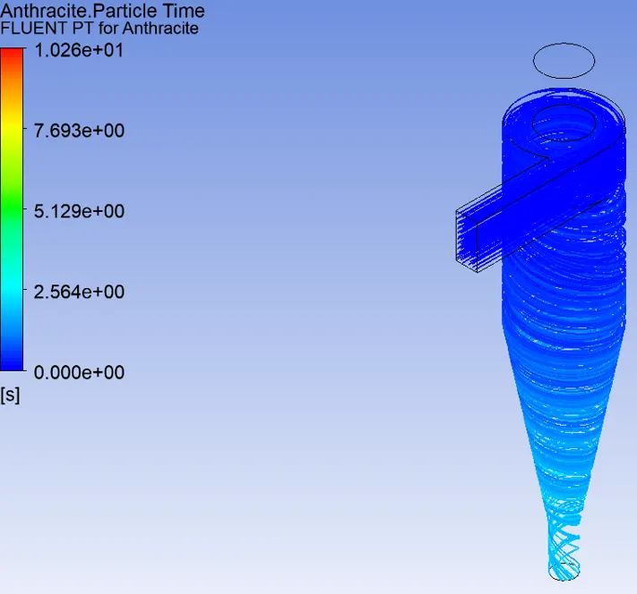
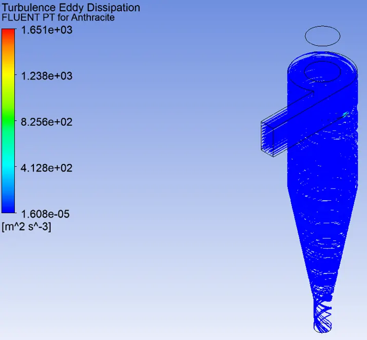
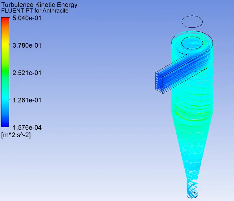
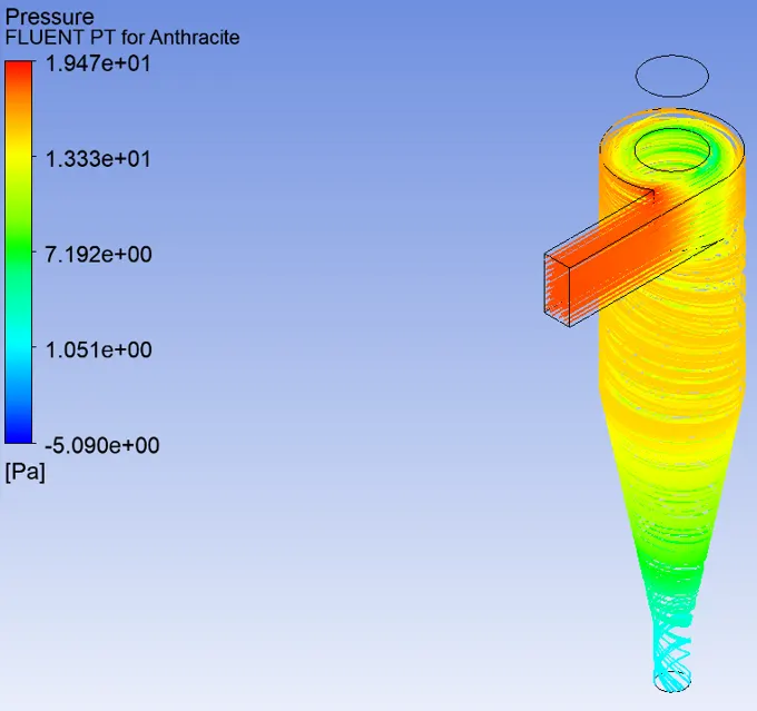

- Separation Efficiency = ((No of particles trapped)/(No of particles tracked))* 100
= (123/124)*100 = 99.20%.
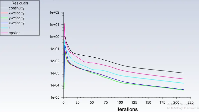
- Inlet veolcity-4m/s, for a particle size of 5µm.
Residual.
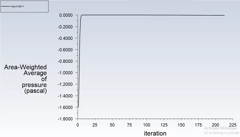
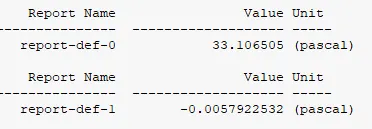
Area weighted average of pressure (pa) at inlet:-
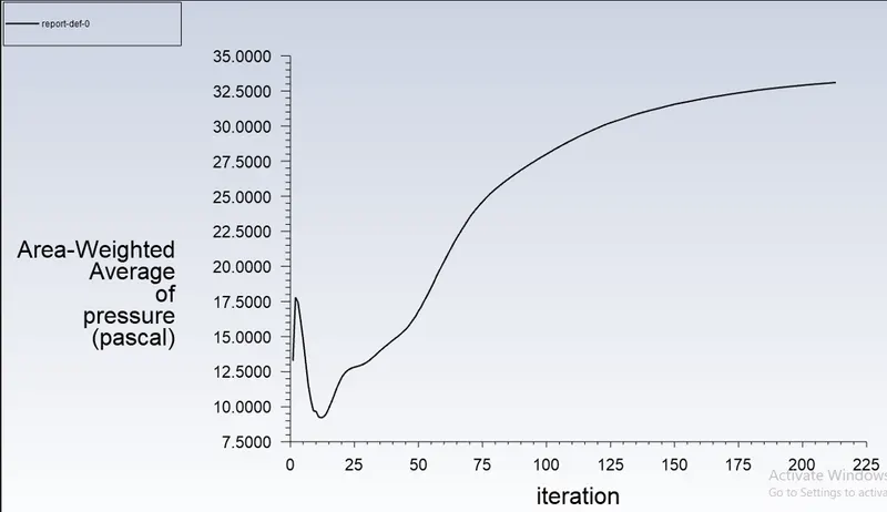
Area weighted average of pressure (pa) at Outlet-1:-
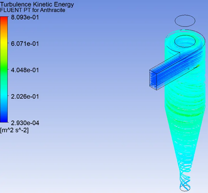
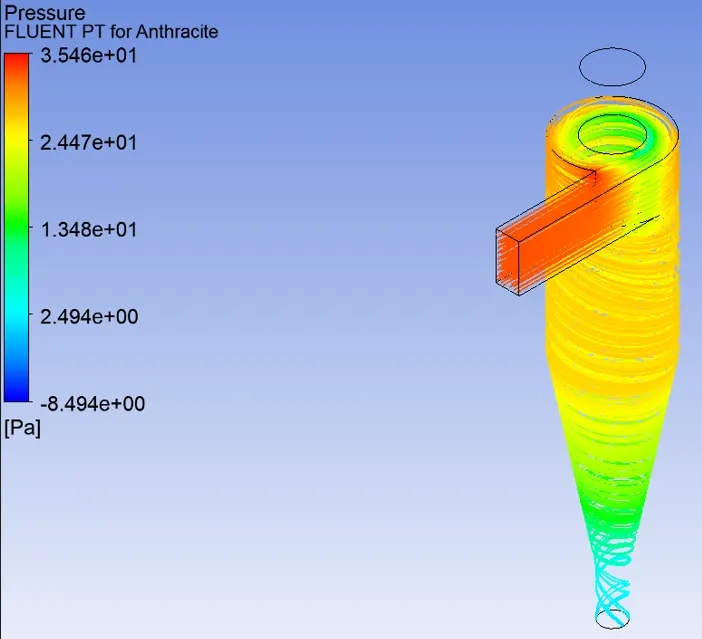
Post processing - Results.
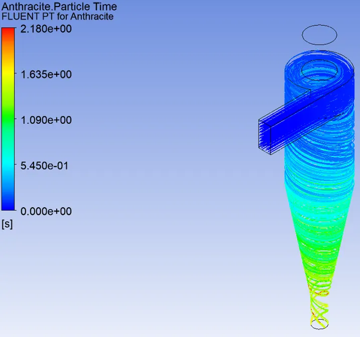
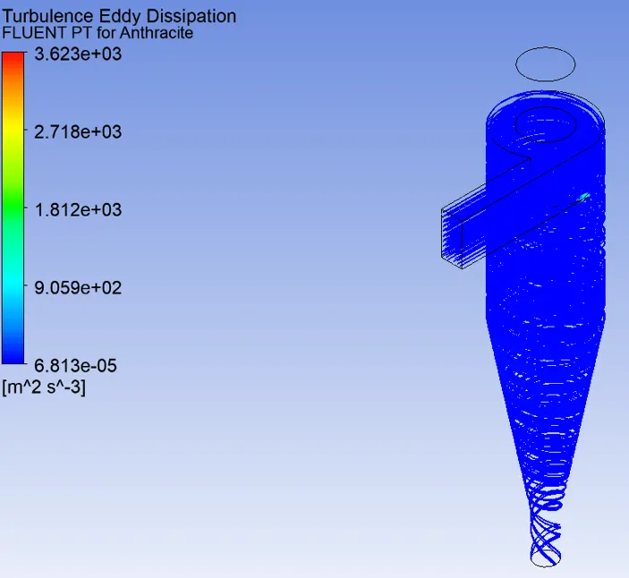

- Separation Efficiency = ((No of particles trapped)/(No of particles tracked))* 100
= (124/124)*100 = 100%.
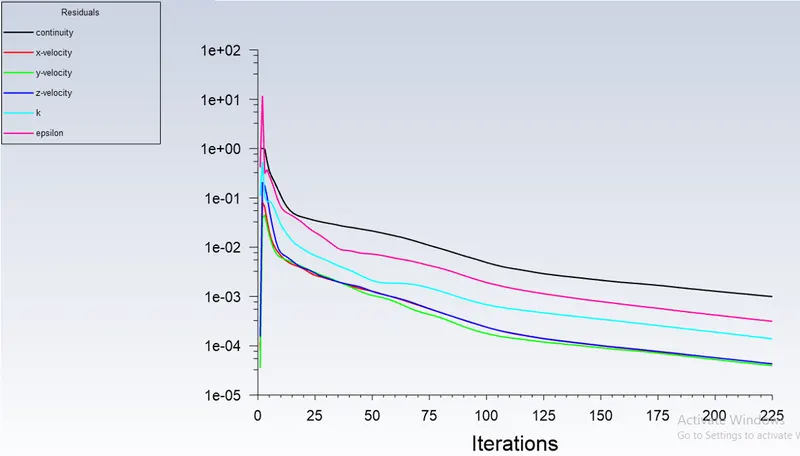
- Inlet veolcity-5m/s, for a particle size of 5µm.
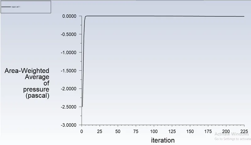
Residual.
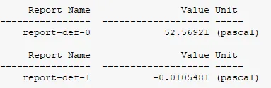
Area weighted average of pressure (pa) at inlet:-
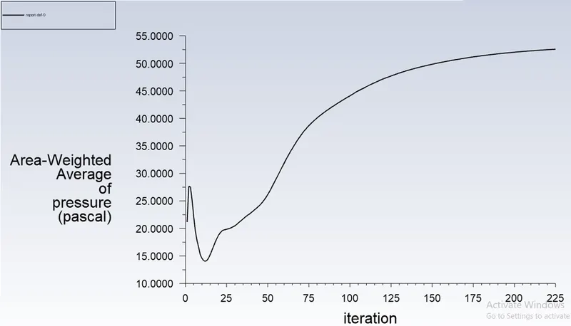
Area weighted average of pressure (pa) at Outlet-1:-
Post processing - Results.
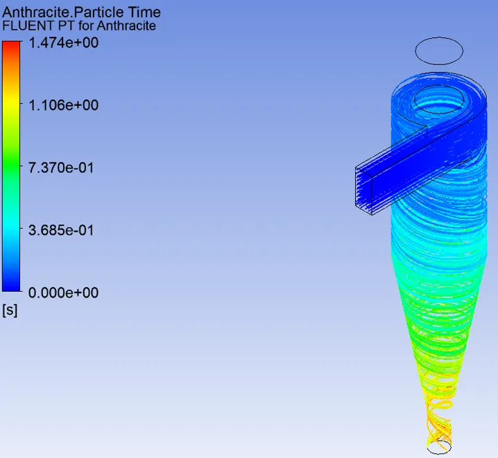
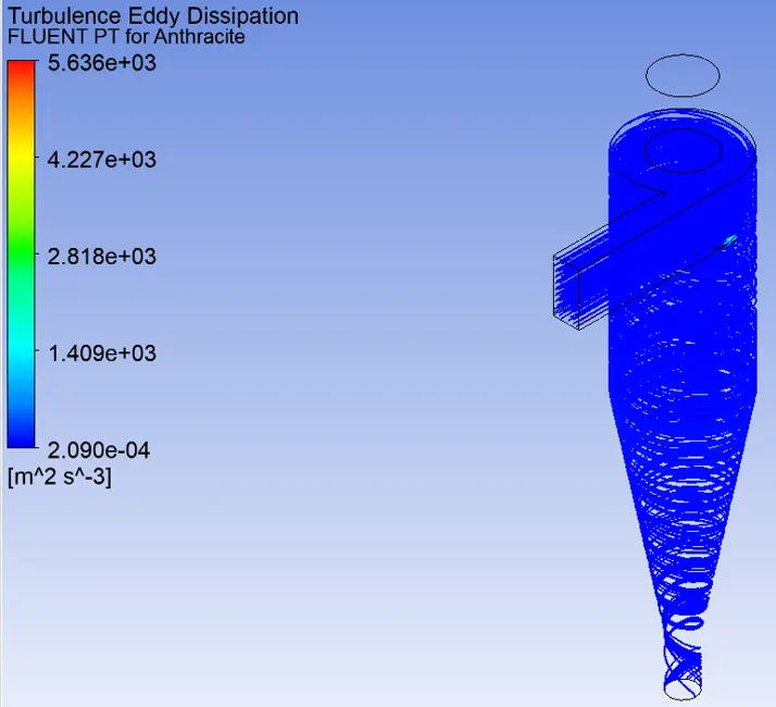
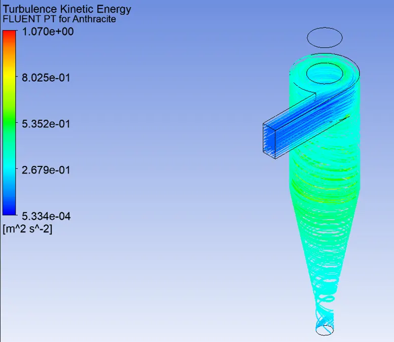
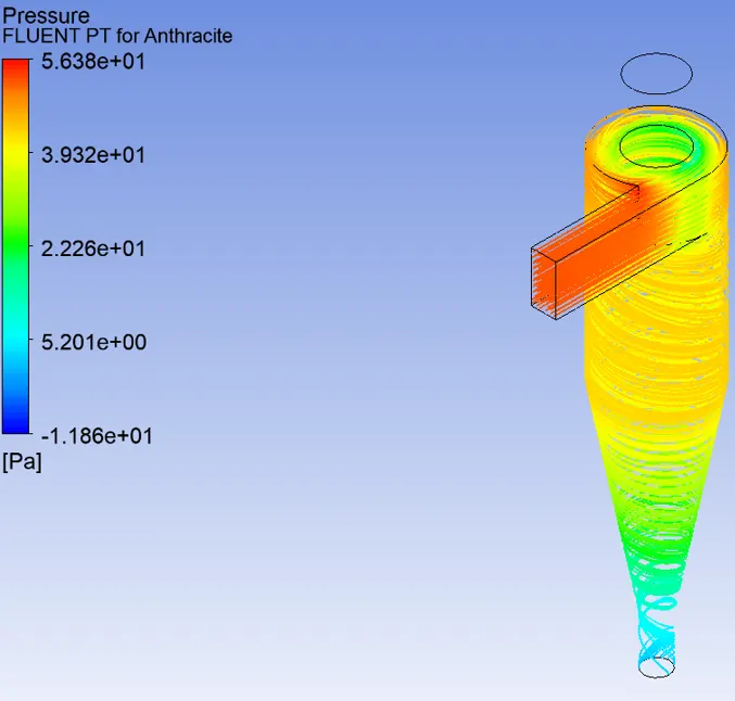

- Separation Efficiency = ((No of particles trapped)/(No of particles tracked))* 100
= (124/124)*100 = 100%.
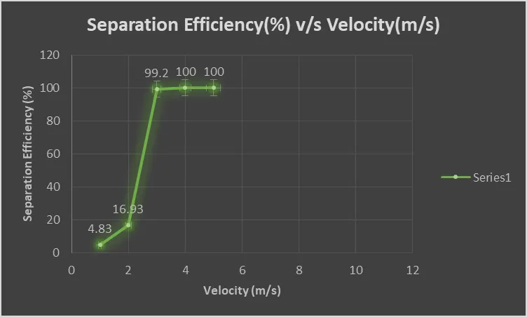
- Plot showing the variation of separation efiiciency of cyclone separator with varying the velocity for a particle size of 5µm.
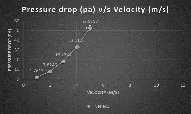
- Plot showing the variation in pressure drop of cyclone separator while varying the velocity from 1 to 5 m/s for a particle size of 5µm.
- Table showing the details of cyclone separator efficiency with pressure drop for a particle size of 5µm with varying velocity.

Conclusion.
- Fom the above simulations its shows that the separation efficiency of the cyclone separator should increases with increasing the particle size.
- The separator efficiency of a cyclone separator is defined as the fraction of particulates at a given size extracted in cyclone, compared to those of that size going into the cyclone. simply the separtion efficiency is defined as the ratio of no of particles trapped to the no of particles tracked.
- Similarly in the second case, it seems that the separtion efficiency of cyclone separator increases while varying the velocity fro 1 o 5 m/s for a particular size of particle.
- Pressure drop is the difference in pressure between the total inlet pressure and total outlet pressure(escape). It seems that increasing the velocity from 1 to 5 m/s the pressure drop also increases.
- Pressure drop is mostly occurs due to losses ie; expansion of the gas in cyclone, frictional forces(wall) and also due to rotational kinetic energy.