Week 8 - Simulating Cyclone separator with Discrete Phase Modelling
Aim:- To perform analysis on cyclone separator and calculate the separation efficiency and pressure drop.
Objective:-
- To write a few words about any four empirical models used to calculate the cyclone separator efficiency.
- To perform an analysis on a given cyclone separator model by varying the particle diameter from 1 μm to 5 μm and calculate the separation efficiency in each case. Discuss the results. [Use both the velocity's as 3m/sec.]
- To perform an analysis on a given cyclone separator model by varying the particle velocity from 1 m/sec to 5 m/sec and calculate the separation efficiency and pressure drop in each case. Discuss the results. [Use particle diameter size as 5 μm for all cases & keep flow velocity same as particle velocity
1. Lapple :-
Lapple model was developed based on force balance without considering the flow resistance. Lapple assumed that a particle entering the cyclone is evenly distributed across the inlet opening. The particle that travels from inlet half width to the wall in the cyclone is collected with 50% efficiency. The semi empirical relationship developed by Lapple [1] to calculate a 50% cut diameter
2. Koch and Licht :-
Koch and Licht collection theory recognized the inherently turbulent nature of cyclones and the distribution of gas residence times within the cyclone. Koch and Licht described particle motion in the entry and collection regions with the additional following assumptions:
- The tangential velocity of a particle is equal to the tangential velocity of the gas flow, i.e. there is no slip in the tangential direction between the particle and the gas.
- The tangential velocity is related to the radius of cyclone
A force balance and an equation on the particles collection yields the grade efficiency
3. Li and wang model :-
The Li and Wang model includes particle bounce or reentrainment and turbulent diffusion at the cyclone wall. A two dimensional analytical expression of particle distribution in the cyclone is obtained. Li and Wang model was developed based on the following assumptions:
- The radial particle velocity and the radial concentration profile are not constant for uncollected particles within the cyclone.
- Boundary conditions with the consideration of turbulent diffusion coefficient and particle bounce reentrainment on the cyclone wall are:
.
4. Iozia and Leith Model :-
Iozia and Leith logistic model is a modified version of Barth Model, which is developed based on force balance. The model assumes that a particle carried by the vortex endures the influence of two forces: a centrifugal force, Z and a flow resistance,
is an expression for slope parameter derived based on the statistical analysis of experimental data of a cyclone with D=0.25 m given as
SIMULATION PROCEDURE :
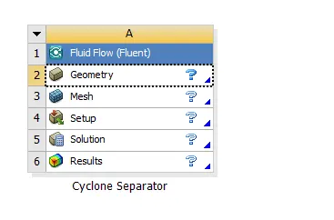
For this challenge, we carry out the simulation procedure in 5 steps namely,
- Geometry
- Meshing
- Setup
- Solution
- Results
1. GEOMETRY
The first step in geometry preparation is importing the step file of the geometry into the ANSYS SpaceClaim software. The model file of the cyclone separator is as shown.
or this geometry, we then perform volume extraction so as to extract the fluid volume surface. We do so using the volume extract function in the prepare geometry tab.
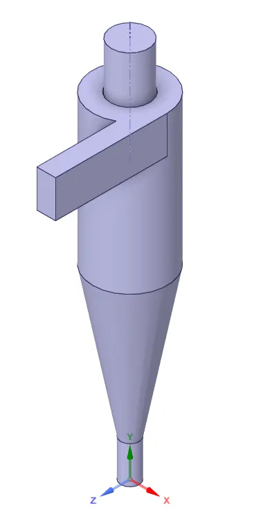
we suppress physics for the outer geometry to make sure that only the fluid volume is imported into meshing
2. MESHING
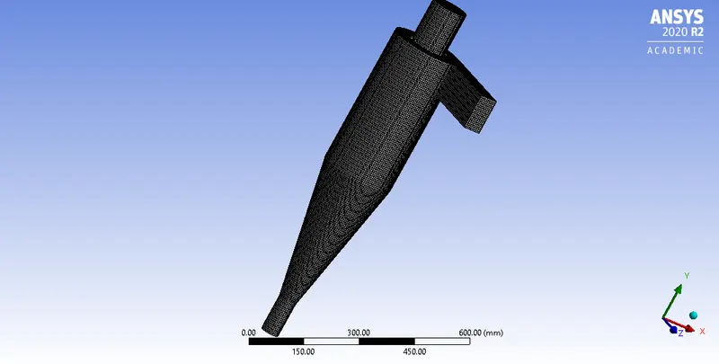
After loading the extracted geometry into meshing, we first create named selections of the inlet and outlet using 10mm cartesian coordinates meshing
4. SETUP
In this step, we are going to provide the necessary parameters to setup the simulation as per the provided data and required output results.
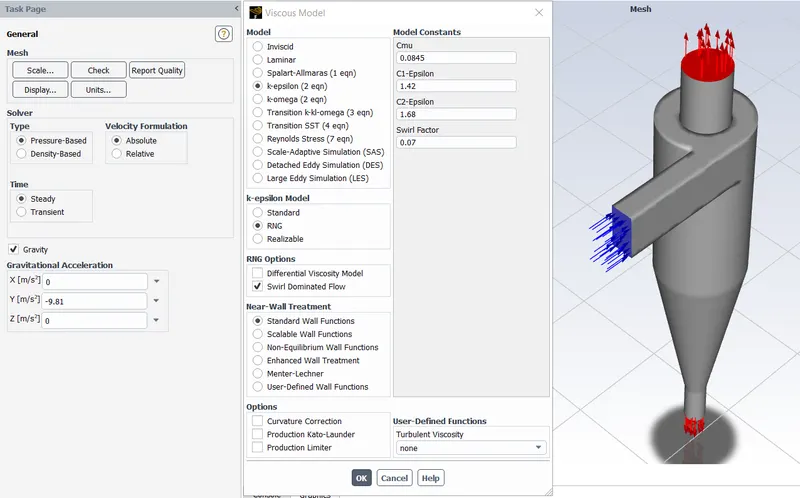
- We use a pressure – based solver with absolute velocity formulation for this simulation.
- We consider steady state time management with gravity enabled in the negative Y – axis for a value of 9.81 m/s.
- K epsilon RNG model
Discrete Phase Modelling :
For this simulation, we use the discrete phase modelling. DPM is employed when we want to represent solid particles in a gas or liquid, such as liquid droplets in a gas and bubbles in a liquid.
Interaction :
- We enable the option of “interaction with continuous phase”, which enables coupled flow of the mixture. This means that there is interaction between the discrete phase and the continuous phase.
- We update the DPM sources every flow iteration at an interval value of 10, which enables us to track the particle source terms at a frequency of 10 intervals.
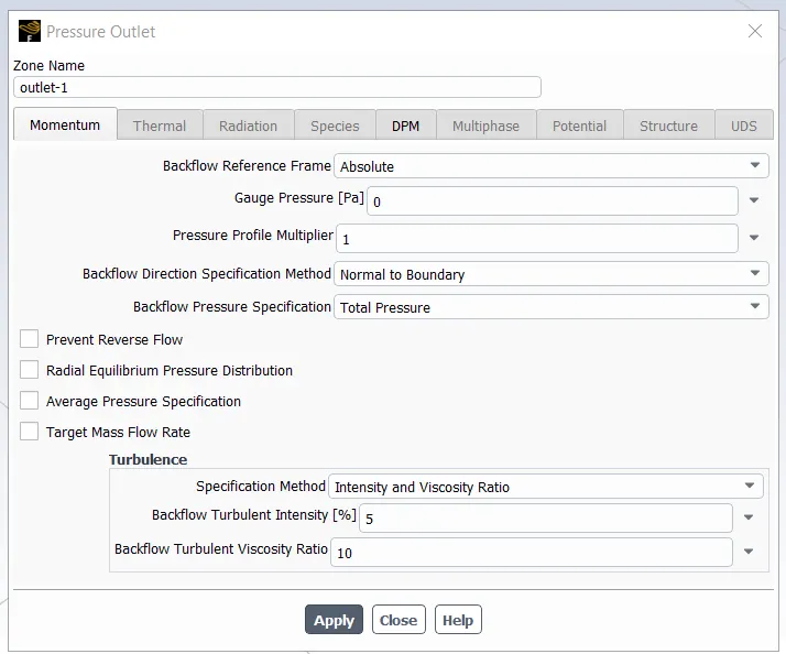
Setting inlet outlet dpm as reflect trap accordingly-
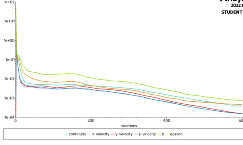
using hybrid initialization we ran sol for 600 iterations-
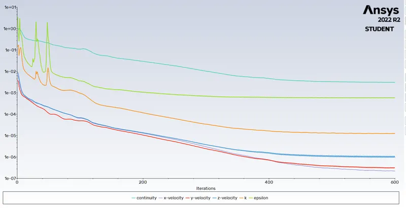
Case 1 (vel 5m/s particle size 5microm) -
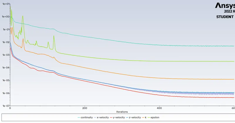
residual plot-
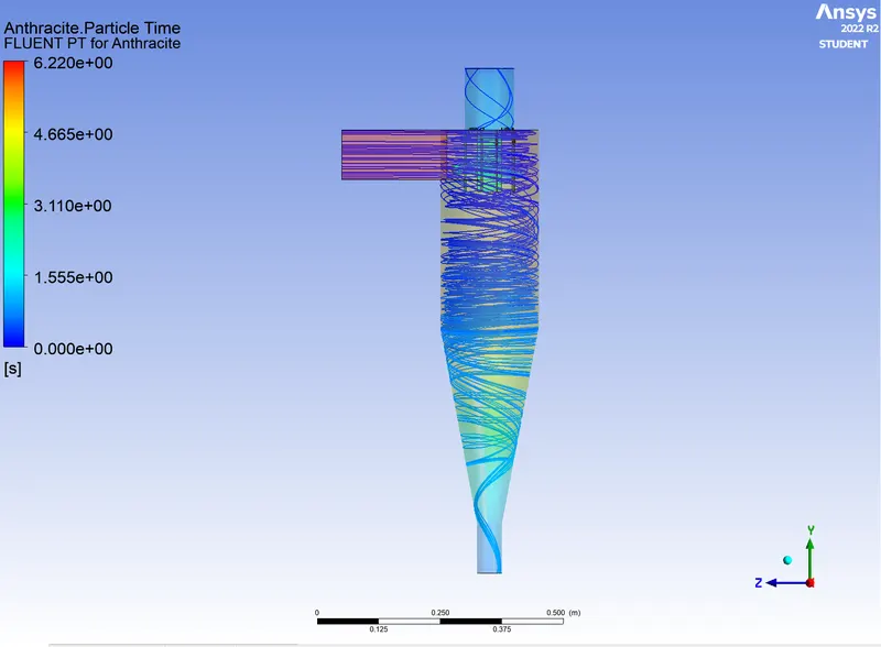
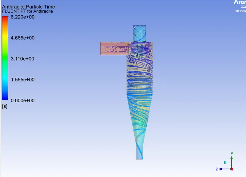
cfd post particle tacking-
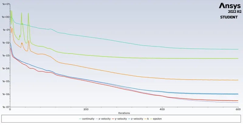
Case 2 (vel 5m/s particle size 1 microm)-
residual plot-
cfd post particle plot-
Case 3 (vel 3m/s particle size 1 microm)-
efficiency
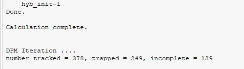
71%
cfd post particle plot-
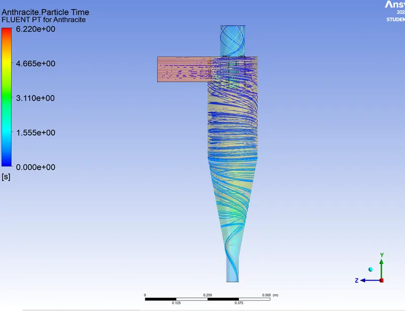
Case 4 (vel 3m/s particle size 5 microm)-
residual plot-
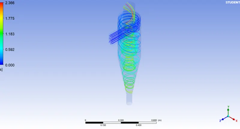
cfd post particle plot-
conclusion-
From the above plot, we can observe that for the same particle size of 5e-6m, as the velocity increases the efficiency of the separator decreases. This is due to the increase in swirling effect as the velocity increase and hence the number of particles escaped also increases. Also, we can see that, for the same inlet velocity of 3 m/s, as the particle size increases the efficiency also increases . This is because the inertial force on the paticles increases as the particles size increases causing the particles to get trapped at the bottom.