Week 8 - Simulating Cyclone separator with Discrete Phase Modelling
CHALLENGE REPORT :
AIM :
To perform analysis on cyclone separator and calculate the separation efficiency and pressure drop.
OBJECTIVE :
* To explain about any four empirical models used to calculate the cyclone separator efficiency.
* To perform an analysis on a given cyclone separator model by varying the particle diameter from 1 μm to 5 μm and calculate the separation efficiency in each case. Discuss the results.
* To perform an analysis on a given cyclone separator model by varying the particle velocity from 1 m/sec to 5 m/sec .
* Calculate the separation efficiency and pressure drop in each case and discuss the results.
INTRODUCTION :
CYCLONE SEPARATOR :
Cyclones are devices that employ a centrifugal force generated by a spinning gas stream to separate particles from the
carrier gas. In a cyclone separator, centrifugal force is used to separate the solids from fluids. The separation process depends not only on the particle size but also on the density of particles. Depending on the fluid velocity, the cyclone separator can be used to separate all types of particles. It is also possible to allow fine particles to be carried by the fluid.
Working Principle :
The solids to be separated are suspended in a stream of gas (usually air). Such a feed is introduced tangentially at a very high velocity so that rotary movement takes place within the vessel. The centrifugal force and vortexing throw the solids to the walls. As the speed of air diminishes, the particles fall to the conical base and are discharged through the solid outlet. The fluid (air) can escape from the central outlet at the top.
Uses :
- It is used to separate the solids from gases.
- It is also used for the size separation of solids in liquids.
- It is used for separating the heavy or coarse fraction from fine dust.
Varients :
Cyclone separators are also used for the size separation of solids suspended in a liquid such as water. Such separators are known as wet or liquid cyclones. One such apparatus used for this purpose is Dorrclone.
CYCLONE EFFICIENCY EMPIRICAL MODELS:
i) Iozia and Leith Model :
Iozia and Leith logistic model is a modified version of Barth Model, which is developed based on force balance. The model assumes that a particle carried by the vortex endures the influence of two forces: a centrifugal force, Z and a flow resistance, W. The collection efficiency ηi of particle diameter dpi can be calculated from
`ηi = 1/( 1 + (dpc/dpi)^ β)`
ii) Li and Wang Model :
The Li and Wang [3] model includes particle bounce or reentrainment and turbulent diffusion at the cyclone wall. A twodimensional analytical expression of particle distribution in the cyclone is obtained. Li and Wang model was developed based on the following assumptions:
i.The radial particle velocity and the radial concentration profile are not constant for uncollected particles within the cyclone.
ii.Boundary conditions with the consideration of turbulent diffusion coefficient and particle bounce re- entrainment on the cyclone wall are:
The collection efficiency of particle of any size is given as:
`ηi = 1 − exp{−λθ1}`
iii) Koch and Licht Model :
kotch and litch collection theory recognized the inherently turbulent nature of cyclones and the distribution of gas residence times within the cyclone. kotch and litch described the particle motion in the entry and collection regions with additional following assumptions:
- The tangential velocity of a particle is equal to the tan- gential velocity of the gas flow, i.e. there is no slip in the tangential direction between the particle and the gas.
- The tangential velocity is related to the radius of cyclone by: uR^n= constant.
A force balance and an equation on the particles collection yields the grade efficiency ηi

iv) Lapple Model :
Lapple model was developed based on force balance without considering the flow resistance. Lapple assumed that a particle entering the cyclone is evenly distributed across the inlet opening. The particle that travels from inlet half width to the wall in the cyclone is collected with 50% efficiency. The semi empirical relationship developed by Lapple to calculate a 50% cut diameter.
The efficiency of collection of any size of particle is given by :
`ηi = 1 / (1 + (dpc/dpi) ^2)`
DISCRETE PHASE MODEL :
The discrete Phase Model is a subsection of Multiphase flows. A discrete phase model (DPM) is used when the aim is to investigate the behavior of the particles from a Lagrangian view and a discrete perspective. The difference between the Lagrangian and the Eulerian view is that fluid behavior in the Lagrangian view is examined based on particle tracking of a particulate flow, whereas fluid behavior is considered in the Eulerian view based on the assumption of a finite volume element in the fluid flow path.
In Discrete Phase Model, the continuous phase is solved using Navier-Stokes equations. At the same time, the discrete phase is simulated by tracking a large number of particles, bubbles, or droplets passing through the calculated continuous flow field. It should be noted that the discrete phase can exchange momentum, mass, and energy with the continuous phase. This method can be made much simpler by ignoring the interaction of particles (as well as droplets and bubbles) with each other. Of course, this can happen when the discrete phase, even with a large mass, has a much smaller volume (less than 10%) than the continuous phase. After each iteration of the continuous phase calculations, the particle paths are calculated and determined separately.
PROCEDURE :
GEOMENTRY SETUP :
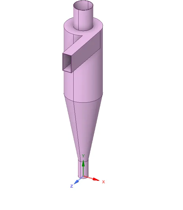
* Just import the model from the problem by opening the space claim .
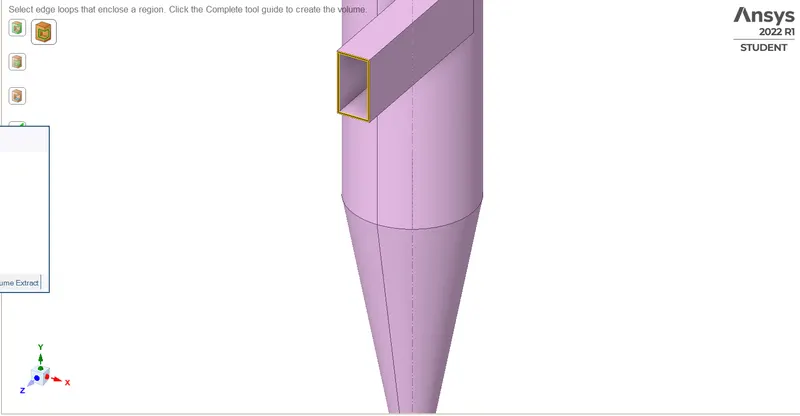
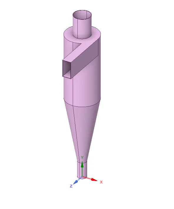
* Create the fluid volume by selecting the edges with the help of volume extract option under repair menu in the space claim.
* For the outer shell aplly the supress for physics, so that we can only have the extracted volume.
MESH :
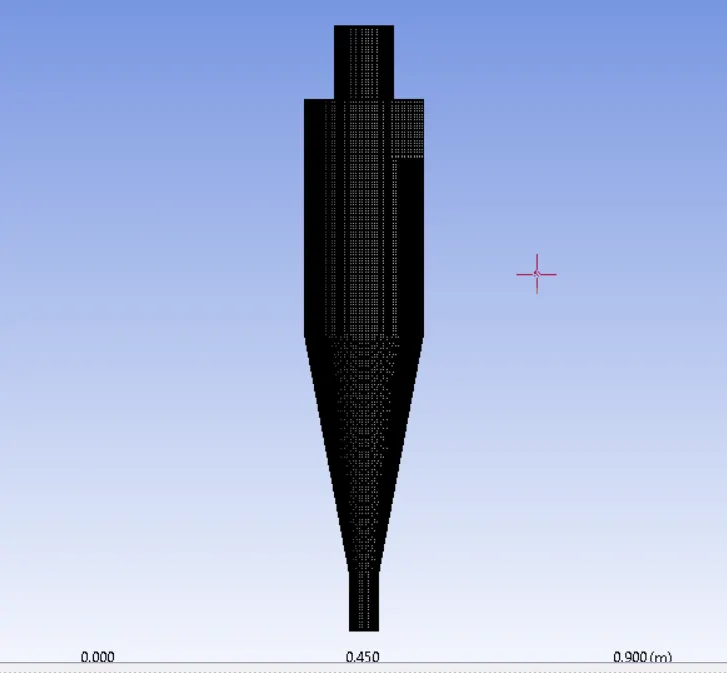
* Created geomentry is opened in the mesh module and give generate mesh.
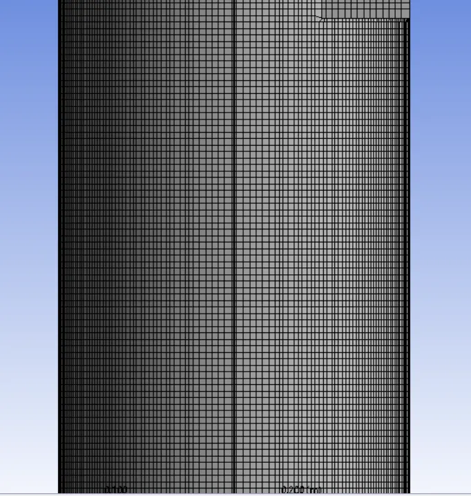
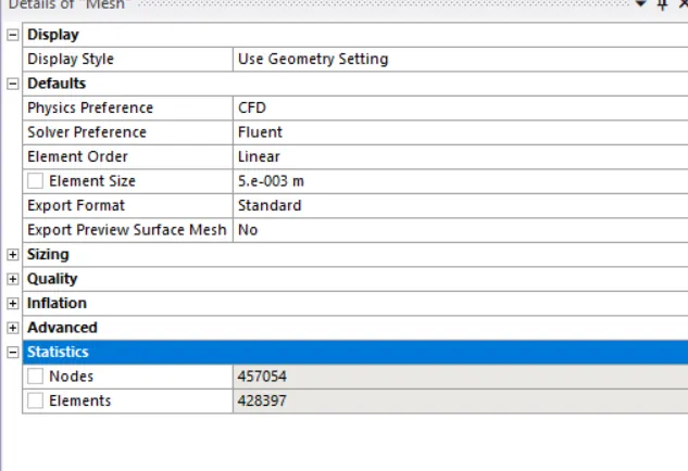
* Given mesh size is 0.005mm and use the structural mesh which gives the better result, so cutcell meshing (cartesian cell) approach is used .
Mesh ---> Insert ---> Method ---> select full model ---> switch the element to cartesian
SETUP SOLUTION :
* After the mesh open the set up modul and here we have to set the condition like physics, boundery conditions, type of analysics, Solution setups and the requried outups.
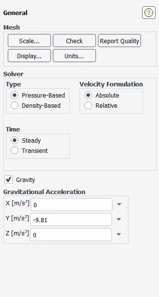
* Here enable the steady state solver because we don't need simulation results for each and every seconds so we need to consider the result of final stage. Pressure based is used because the velocity of air is low ( less than 0.3 of mach number ) and enable gravity with Y axis as -9.81 .
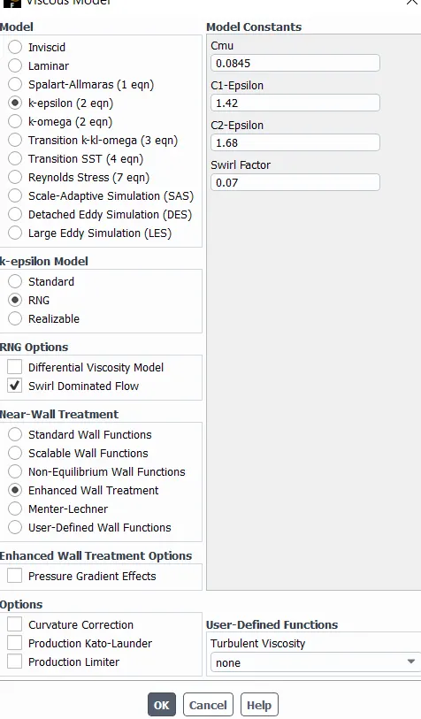
* Use K-epcelon model by opening the Viscous option in the physics and select the RNS because some of swirl and edes are formed here and Enhanced Wall Treatments under the near wall treatment.
* Select the discrete phase option in the physics tab and enable the continuous phase which is used to exceed the energy between particle and fluid. DPM iteration is set to be default 10.
Physics ---> Discrete phase ---> Contiuous phase ---> DPM iteration interval (10)
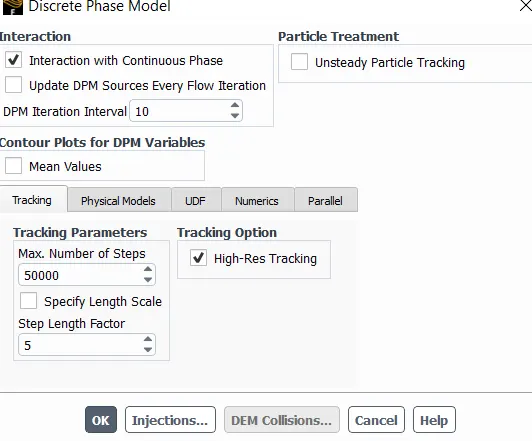
* Select the Injection which is found below the discrete phase tab and create the new injection by selecting the type as surface and surface as inlet and material as anthracite and enable the face normal option and set the particle size and velocity.
Injection ---> Create ---> Type (surface) ---> Surface (inlet) ---> Material (anthracite) ---> Enable Face normal ---> set size and velocity of particles.
Three cases are performed :
CASE 1:
Particle size = 1 micrometer
Particle velocity = 3m/s
CASE 2:
Particle size = 3 micrometer
Particle velocity = 3m/s
CASE 3:
Particle size = 5 micrometer
Particle velocity = 1m/s
CASE 4:
Particle size = 5 micrometer
Particle velocity = 3m/s
CASE 5:
Particle size = 5 micrometer
Particle velocity = 5m/s
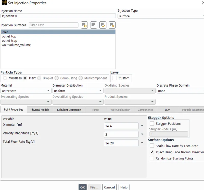
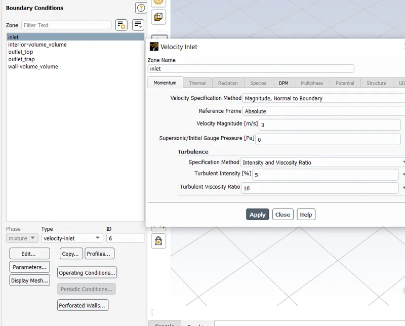
* Set the boundaries with inlet as 3m/s velocity, DPN is reflector and Oulet top with pressure based, DPN is escape and Oulet trap as pressure based, DPN is Trap.
Boundary Conditions:-
Inlet ----> Reflect
Outlet Top ----> Escape
Outlet Trap ----> Trap
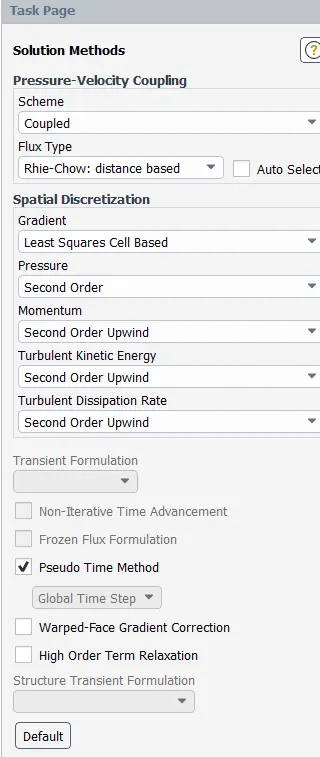
* Select the Method and enable the Coupled as we used steady state and choose the second orde in the momentum so that it gives good results but takes more memory and time.
* Initialize with standard initialization as it solve based on the boundaries( select the inlet ).
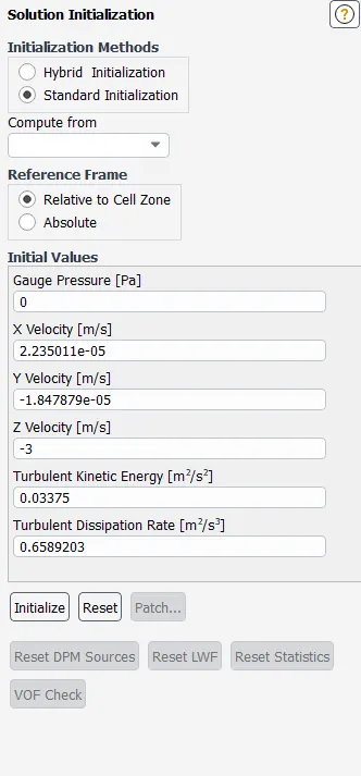
* Set the No of iteration as 500 and calculate.
CFD POST :
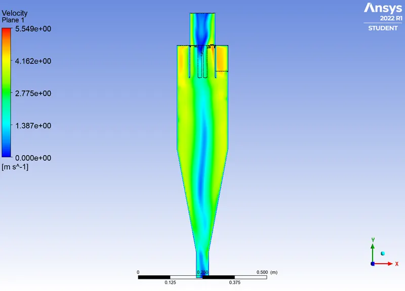
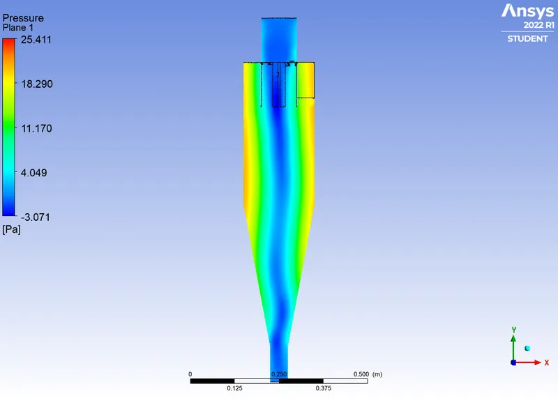
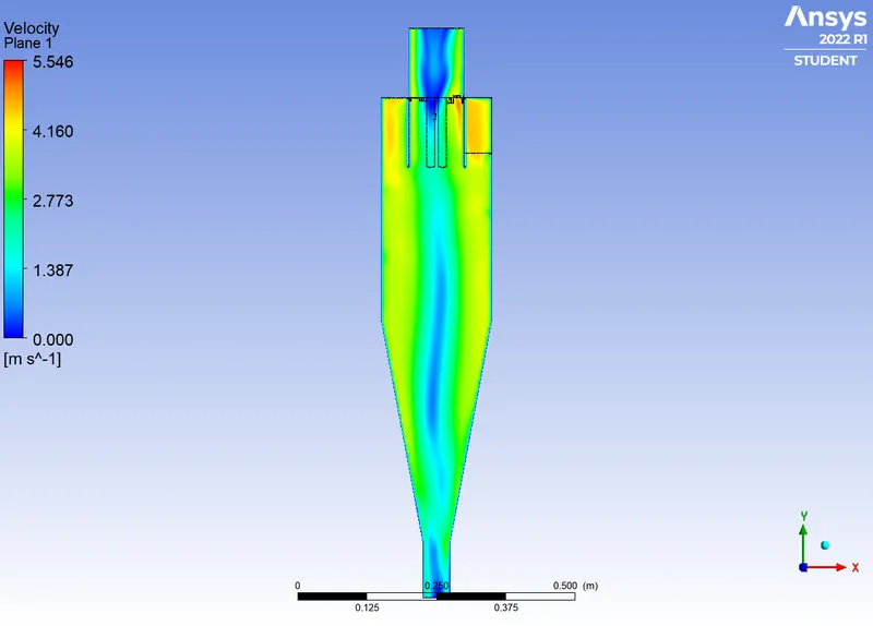
* Create the Pressure contours and velocity contours.
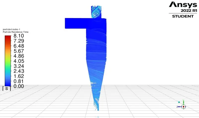
* Create the contours for particle separation.
RESULT :
CASE 1 :
PARTICAL DIAMETER = 1 micrometer
PARTICAL VELOCITY = 3 m/s
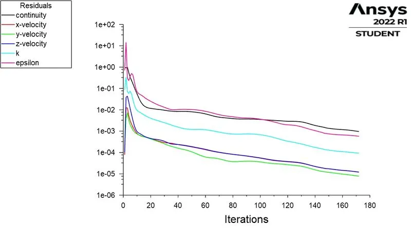
RESIDUAL PLOT :
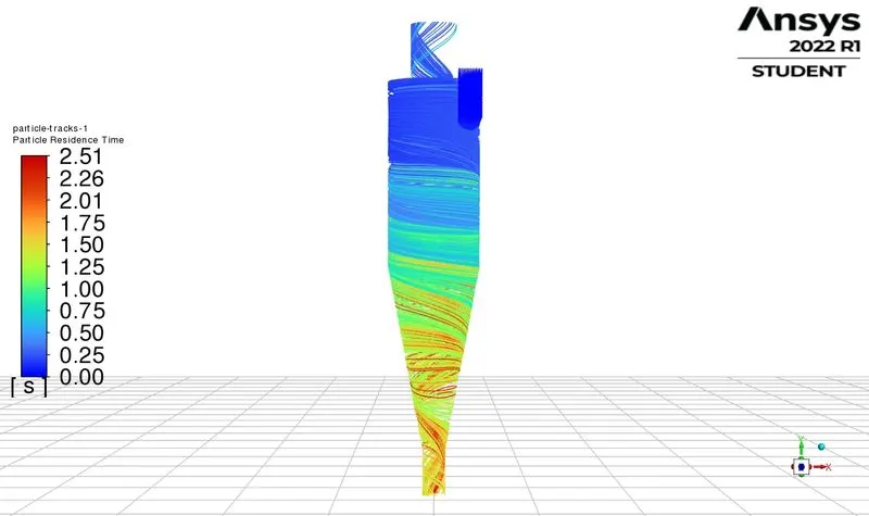
PARTICLE RESIDUAL TIME :
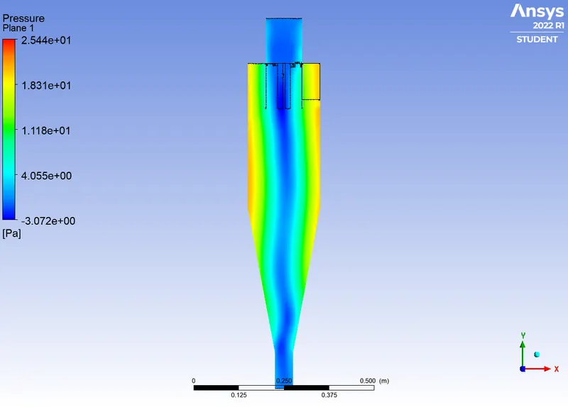
PRESSURE CONTOUR :
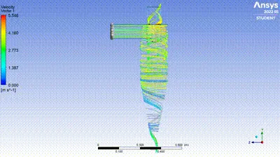
VELOCITY CONTOUR :
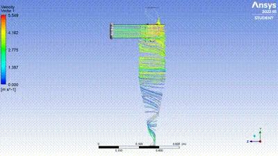
VIDEO :
CASE 2 :
PARTICAL DIAMETER = 3 micrometer
PARTICAL VELOCITY = 3 m/s
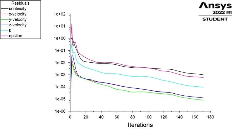
RESIDUAL PLOT :
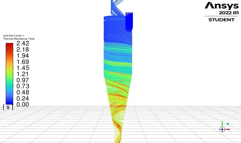
PARTICLE RESIDUAL TIME :
PRESSURE CONTOUR :
VELOCITY CONTOUR :
VIDEO :
CASE 3 :
PARTICAL DIAMETER = 5 micrometer
PARTICAL VELOCITY = 1 m/s
RESIDUAL PLOT :
PARTICLE RESIDUAL TIME :
PRESSURE CONTOUR :
VELOCITY CONTOUR :
VIDEO :
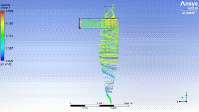
CASE 4 :
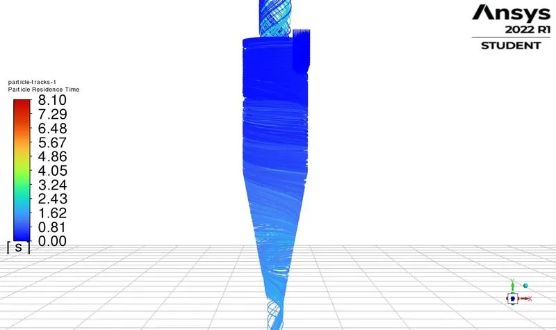
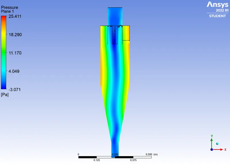
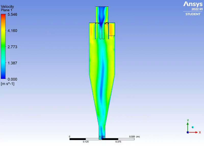
PARTICAL DIAMETER = 5 micrometer
PARTICAL VELOCITY = 3 m/s
RESIDUAL PLOT :
PARTICLE RESIDUAL TIME :
PRESSURE CONTOUR :
VELOCITY CONTOUR :
VIDEO :
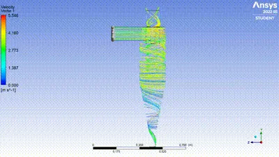
CASE 5 :
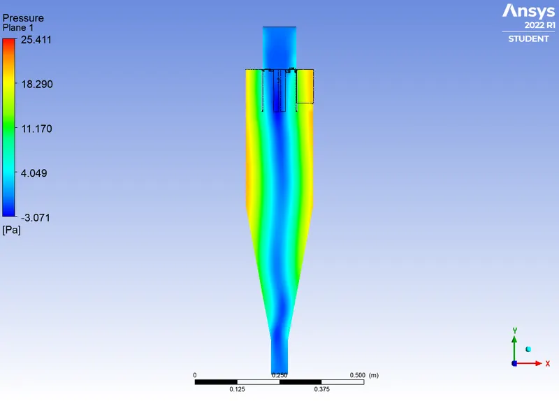
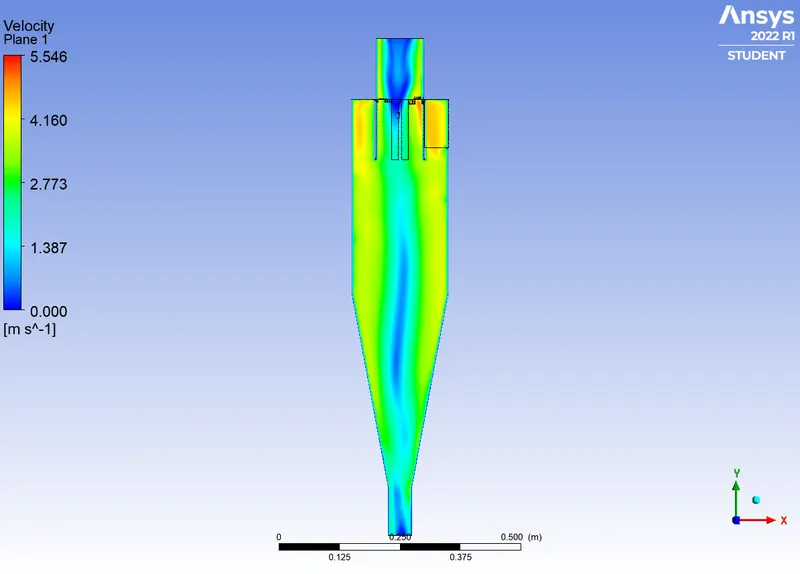
PARTICAL DIAMETER = 5 micrometer
PARTICAL VELOCITY = 5 m/s
RESIDUAL PLOT :
PARTICLE RESIDUAL TIME :
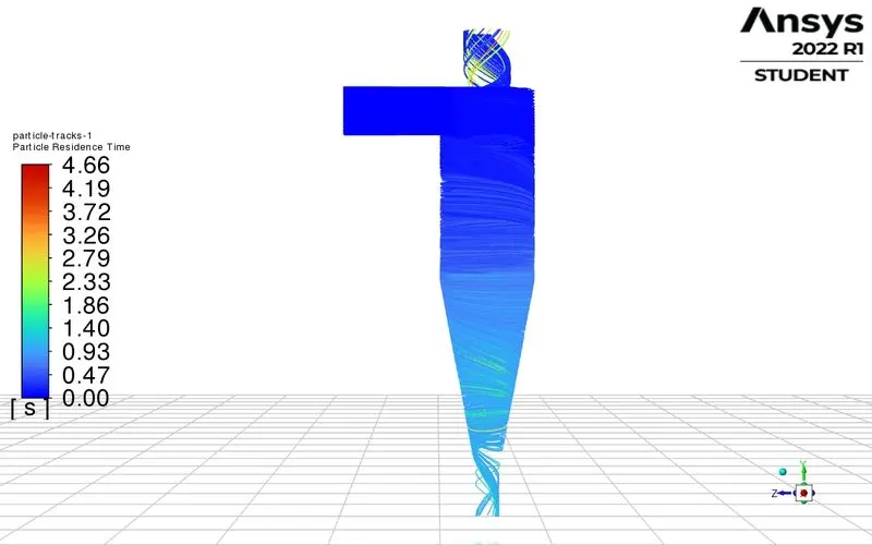
PRESSURE CONTOUR :
VELOCITY CONTOUR :
VIDEO :
CALCULATION FOR EFFICIENCY :
Efficiency = ( No of particle trap / No of particle tracked ) * 100
For case 1 :
efficiency = 309 / 378
= 81.746
For case 2 :
efficiency = 312 / 378
= 82.539
For case 3 :
efficiency = 305 / 378
=80.68
For case 4 :
efficiency = 243 / 378
= 64.285
For case 5 :
efficiency = 289 / 378
= 76.455
| CASES | PARTICLE DIAMETER |
PARTICLE VELOCITY |
NO OF PARTICLES TRACKED | ESCAPED | TRAPPED | EFFICIENCY |
| 1 | 1 micrometer | 3 m/s | 378 | 69 | 309 | 81.746 |
| 2 | 3 micrometer | 3 m/s | 378 | 66 | 312 | 82.539 |
| 3 | 5 micrometer | 1 m/s | 378 | 72 | 305 | 80.68 |
| 4 | 5 micrometer | 3 m/s | 378 | 134 | 243 | 64.285 |
| 5 | 5 micrometer | 5 m/s | 378 | 87 | 289 | 76.455 |
CALCULATION FOR PRESSURE DROP :
Pressure drop = Total inlet pressure - Total outlet pressure
Case 1 :
Pressure drop = 30.3516 - 4.264
= 26.087
Case 2 :
Pressure drop = 30.326 - 4.264
= 26.362
Case 1 :
Pressure drop = 2.717 - 0.304
= 2.376
Case 1 :
Pressure drop = 31.326 - 4.52
= 26.806
Case 1 :
Pressure drop = 91.201 - 13.125
= 78.076
| CASES | PARTICLE SIZE | PARTICLE VELOCITY | INLET PRESSURE | OUTLET (TOP) PRESSURE | OUTLET (TRAP) PRESSURE | PRESSURE DROP |
| 1 | 1 micrometer | 3 m/s | 30.351 | 4.264 | 2.223 | 26.087 |
| 2 | 3 micrometer | 3 m/s | 30.326 | 3.964 | 2.221 | 26.362 |
| 3 | 5 micrometer | 1 m/s | 2.717 | 0.3407 | 0.237 | 2.376 |
| 4 | 5 micrometer | 3 m/s | 31.326 | 4.52 | 0.226 | 26.806 |
| 5 | 5 micrometer | 5 m/s | 91.201 | 13.125 | 6.6404 | 78.076 |
OBSERVATION :
* If the size of the particle is small than the number of particle trap is more where as the large particle shows less capture of paerticles .
* The efficiency of the cyclone separator is depends on the size and velocity of the particles. As the particle size is small than efficiency increases and for large particle size the efficiency decrease. The velocity is increased the number of particles traped is less and more particles will escaped through outlet top and so velocity show to be optimized condition.
* We can conclude that the size of the particle increase the number of particles also increases and so the efficiency of the cyclone separator is increased. The velocity increased the efficiency of the cyclone separator also decreased.
* It is observered from the pressure table that pressure drop is larger for higher velocity and large sized particles when compare to others. It shows that pressure drop is depends on both the size and velocity and parameters like rotational kinetic energy. wall frictional forces. ect.
CONCLUSION :
* Cyclone efficiency will generally increase with the increase in particle size, density, inlet duct velocity, cyclone body length, number of gas revolutions in the cyclone, the ratio of cyclone body diameter to gas exit diameter, inlet dust loading, smoothness of the cyclone inner wall.
* The efficiency of the cyclone will decrease with an increase in the parameters such as gas viscosity, cyclone body diameter, gas exit diameter, gas inlet duct area, gas density, leakage of air into dust outlet. With the increase in inlet velocity or particle size the efficiency increases..
* Pressure drop occurs due to the expansion of gas in the cyclone chamber and due to rotational kinetic energy and wall frictional forces.