Week 8 - Simulating Cyclone separator with Discrete Phase Modelling
Aim
To perform analysis on cyclone separator and calculate the separation efficiency and pressure drop.
Objective:-
- To write a few words about any four empirical models used to calculate the cyclone separator efficiency.
- To perform an analysis on a given cyclone separator model by varying the particle diameter from 1 μm to 5 μm and calculate the separation efficiency in each case. Discuss the results. [Use both the velocity's as 3m/sec.]
- To perform an analysis on a given cyclone separator model by varying the particle velocity from 1 m/sec to 5 m/sec and calculate the separation efficiency and pressure drop in each case. Discuss the results. [Use particle diameter size as 5 μm for all cases & keep flow velocity same as particle velocity]
Theory
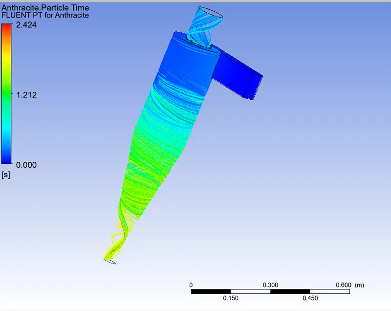
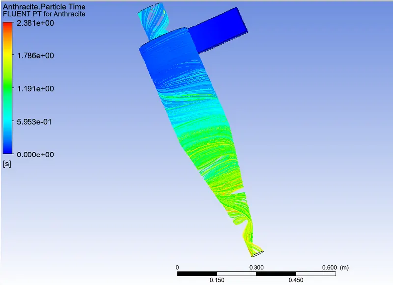
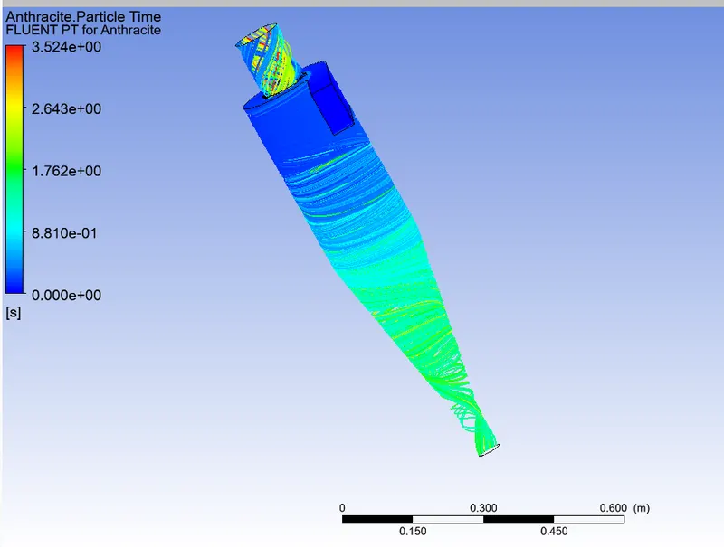
Cyclone separators work much like a centrifuge, but with a continuous feed of dirty air. In a cyclone separator, dirty flue gas is fed into a chamber. The inside of the chamber creates a spiral vortex, similar to a tornado. This spiral formation and the separation is shown in Figure 2. The lighter components of this gas have less inertia, so it is easier for them to be influenced by the vortex and travel up it. Contrarily, larger components of particulate matter have more inertia and are not as easily influenced by the vortex.
Pre-processing and solver setting
Gemotery
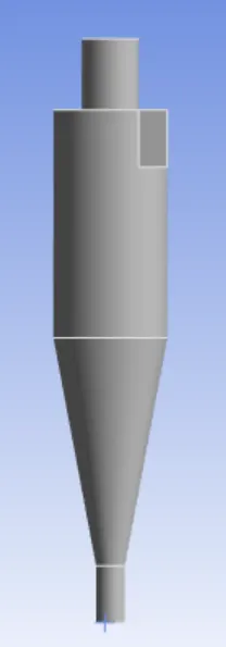
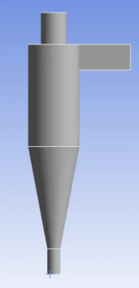
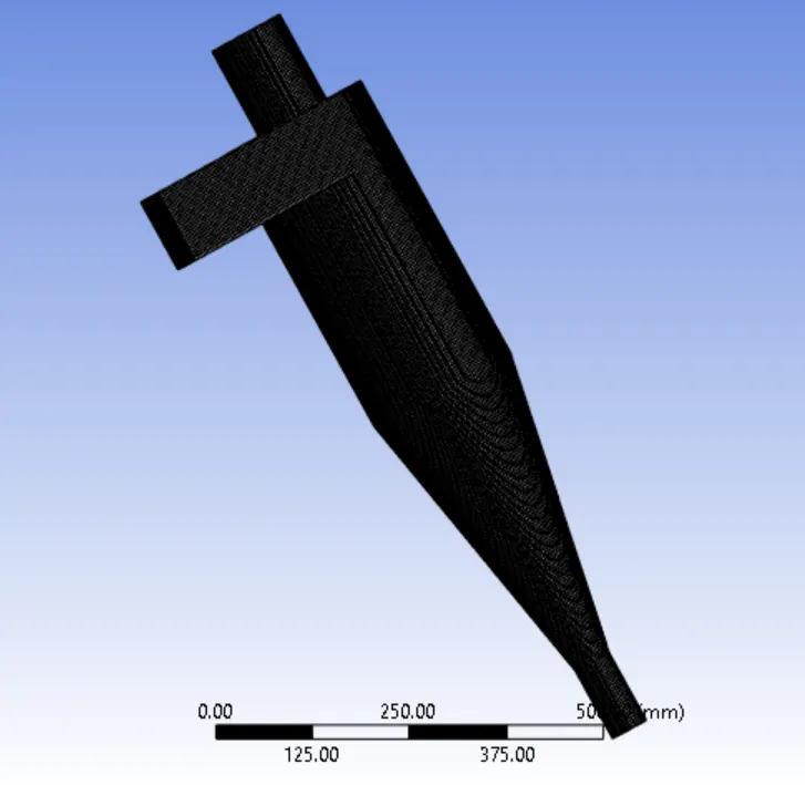
mesh
traget length = 6.0 mm
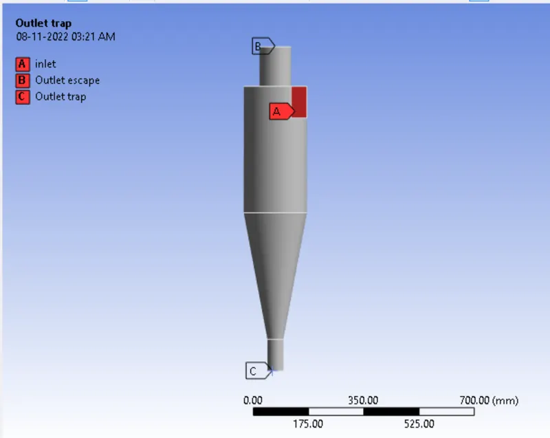
Name selection
Boundary Conditions:-
Inlet and wall:- Reflect
Outlet(Top):- Escape
Outlet(Bottom/dustbin) - Trap
Fluent Setup:
Solver: Steady State solver
Type: Pressure based
Model: k-epsilon RNG, Swril dominated flow, Standard wall function
Injections:
Type - Surface injection
Material type - Antracite
X-velocity - 3m/s
Diameter - varying from 1e-6 to 5e-6
Flow rate - 1e-20 kg/s
case -1
partical diameter = 1e-6
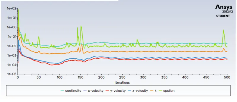
contour plot
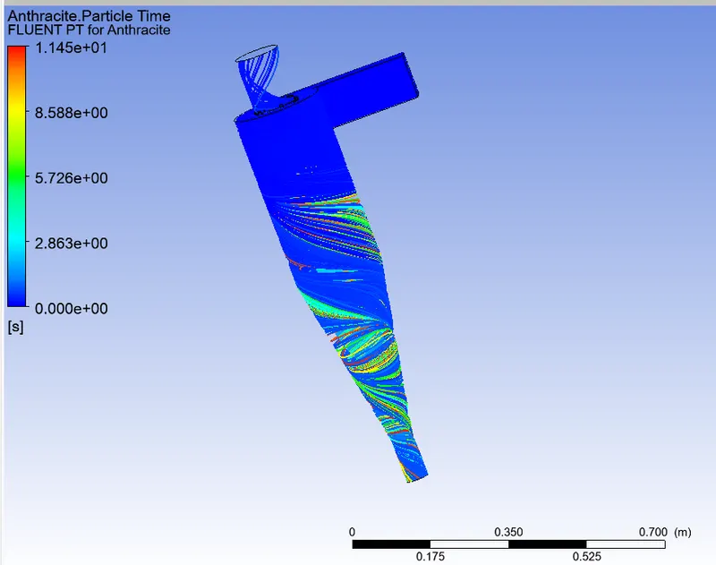
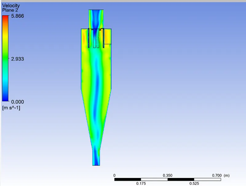
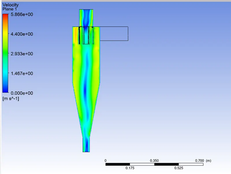
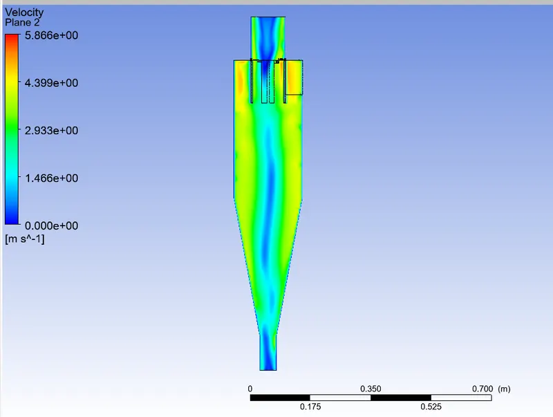
velocity contour
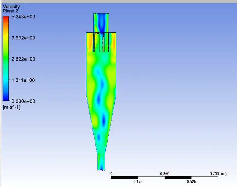
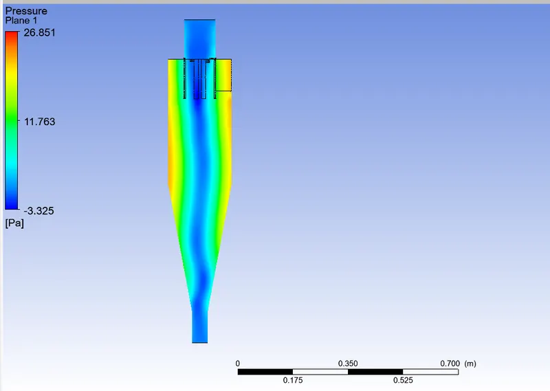
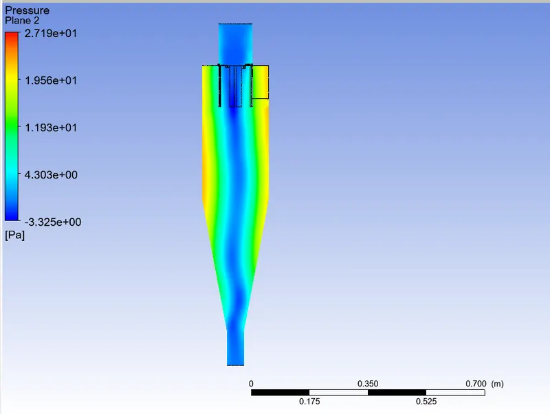
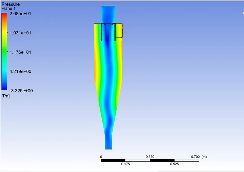
pressure contour
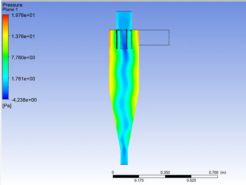
partical diameter = 2e-6
partical diameter = 3e-6
contour plot
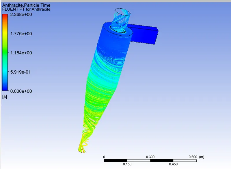
partical diameter = 4e-6
partical diameter = 5e-6
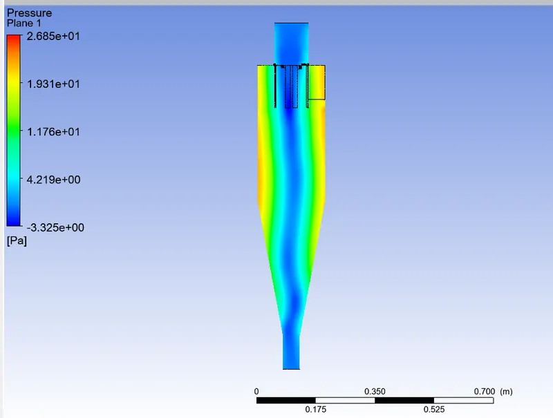
pessure contour
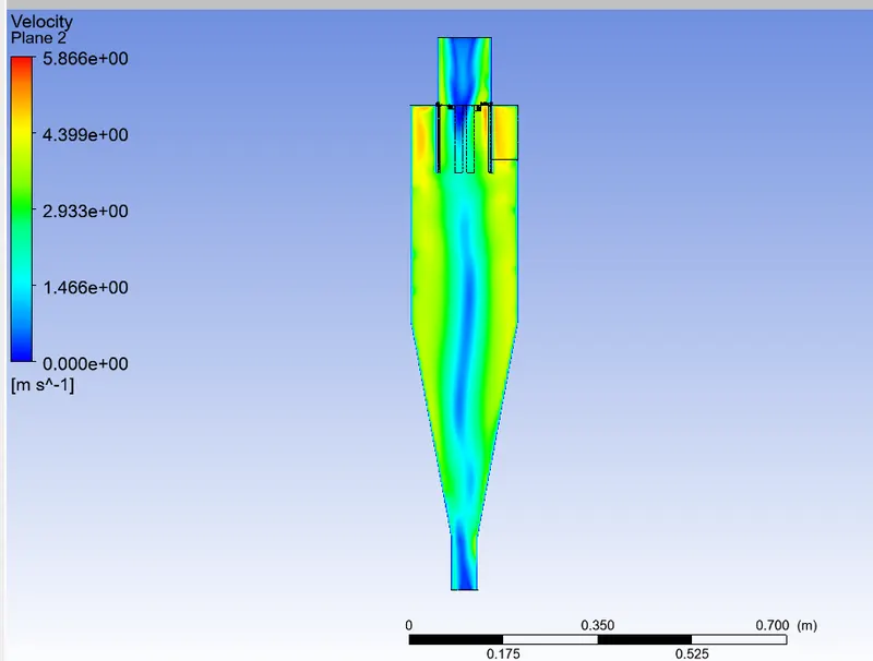
velocity contour
seperation efficiency = number of patical trapped / number of partical tracked
| No | particla diameter | partical velocity | flow velocity | number of particla tracked | number of partical escaped | number of the partical trapped | separtion of effeciency | |
| 1 | 1e-6 | 3 m/s | 3 m/s | 378 | 33 | 271 | 71 | |
| 2 | 2e-6 | 3 m/s | 3 m/s | 378 | 27 | 305 | 80 | |
| 3 | 3e-6 | 3 m/s | 3 m/s | 378 | 72 | 306 | 79 | |
| 4 | 4e-6 | 3 m/s | 3 m/s | 378 | 87 | 291 | 75 | |
| 5 | 5e-6 | 3 m/s | 3 m/s | 387 | 25 | 247 | 63 |
case -2
partical velocity 1m/s to 5m/s
partical velocity = 1 m/s
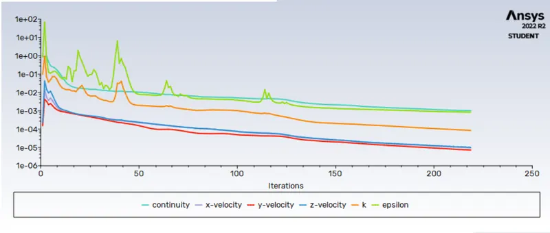
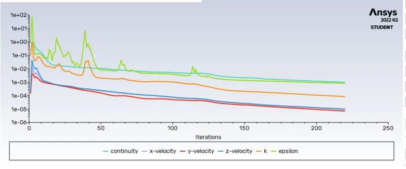
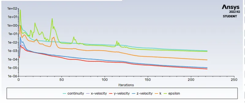
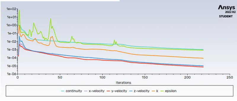
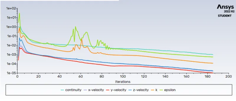
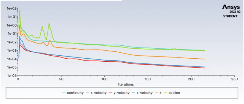
residual
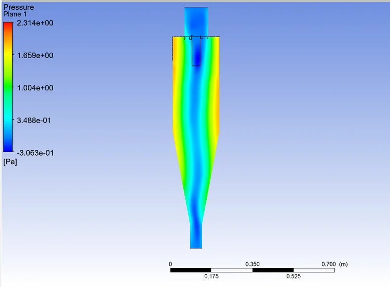
pressure contour
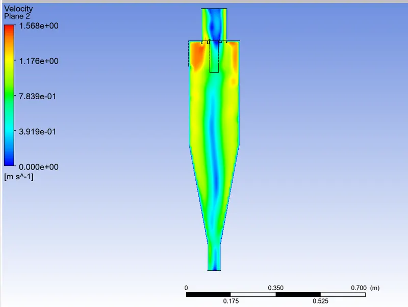
velocity contour
partical velocity =2
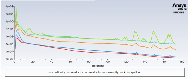
residual
pressure contour
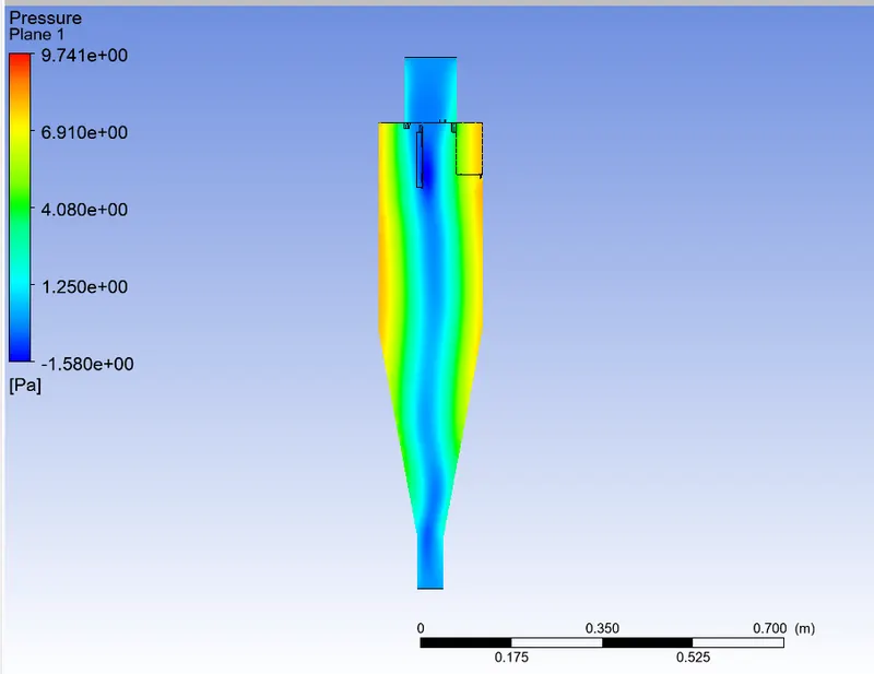
velocity contour
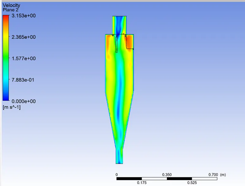
partical velocity =3
residual
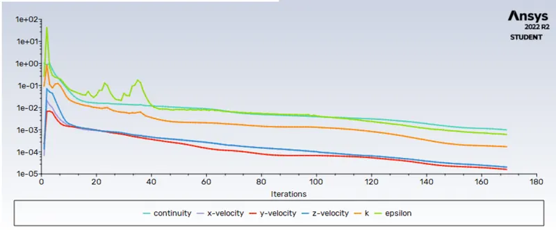
pressure contour

velocity contour
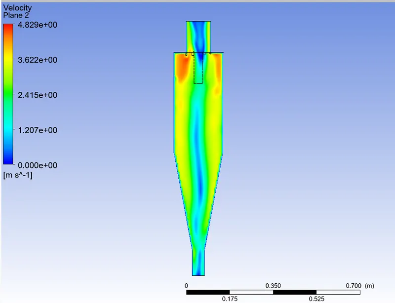
particla velocity =4
residual
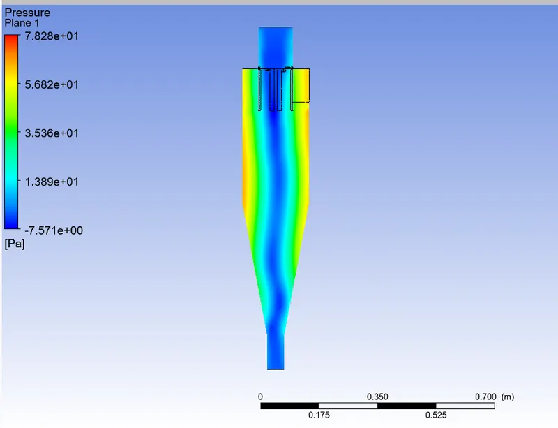
pressure contour
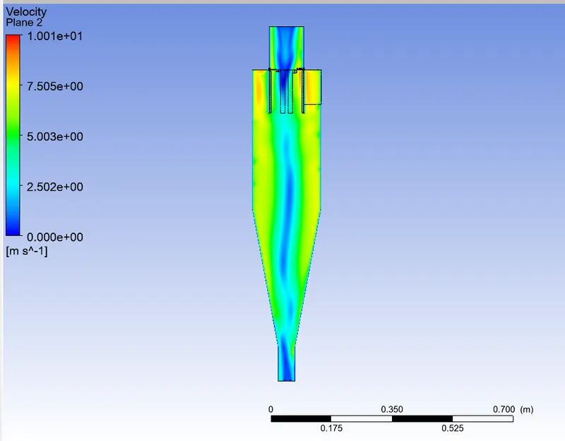
velocity contour
| No | particla diameter | partical velocity | flow velocity | number of particla tracked | number of partical escaped | number of the partical trapped | separtion of effeciency | |
| 1 | 5e-6 | 1 m/s | 1 m/s | 136 | 12 | 124 | 91 | |
| 2 | 5e-6 | 2 m/s | 2 m/s | 136 | 21 | 114 | 83 | |
| 3 | 5e-6 | 3 m/s | 3 m/s | 136 | 41 | 95 | 69 | |
| 4 | 5e-6 | 4 m/s | 4 m/s | 378 | 127 | 251 | 66 | |
| 5 | 5e-6 | 5 m/s | 5 m/s | 387 | 74 | 281 | 72 |
Result
When the diameter of the particle varies from 1 μm to 5μm by keeping the flow velocity constant of 3m/s the separation efficiency increases .As the velocity of the particle varies from 1m/s to 5m/s by keeping the particle diameter constant of 5μm the separation efficiency increases. Increasing the velocity of particle causes high pressure drop.