Week 8 - Simulating Cyclone separator with Discrete Phase Modelling
AIM:
- To simulate the flow through a cyclone separator and show the results for the different particle sizes and different velocities.
OBJECTIVE:
- Write a few words about any four empirical models used to calculate the cyclone separator efficiency.
- An analysis to perform a given cyclone separator model by varying the particle diameter from 1 μm to 5 μm and calculate the separation efficiency in each case. Discuss the results. (In both cases the velocity could be constant at 3m/sec.)
- To perform an analysis on a given cyclone separator model by varying the particle velocity from 1 m/sec to 5 m/sec and calculate the separation efficiency and pressure drop in each case. Discuss the results. (Use particle diameter size constant at 5 μm for all the cases & keep flow velocity the same as particle velocity)
THEORY:
Cyclone Separator:
- In a cyclone separator, centrifugal force is used to separate the solids from fluids. The separation process depends not only on the particle size but also on the density of particles. Depending on the fluid velocity, the cyclone separator can be used to separate all types of particles. It is also possible to allow fine particles to be carried by the fluid.
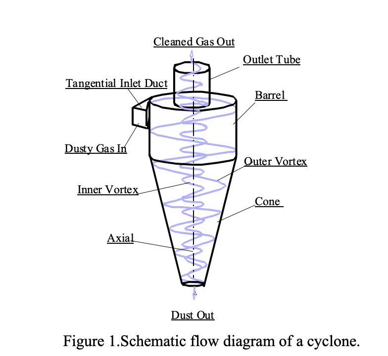
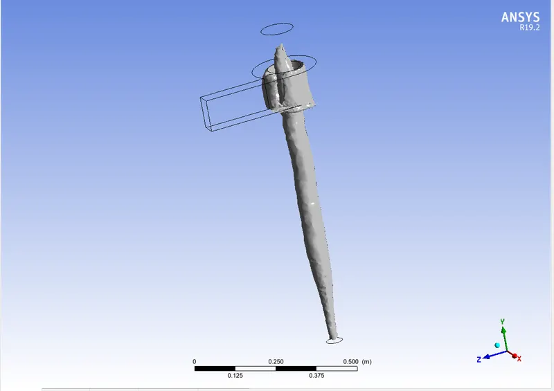
- The construction of a cyclone separator is shown in Figure. It consists of a short vertical, cylindrical vessel with a conical base. The upper part of the vessel is fitted with a tangential inlet. The outlet (solid outlet) is arranged at the base. A fluid outlet is provided at the center of the top portion, which extends inwardly into the separator. Such an arrangement prevents the air from short-circuiting directly from the inlet to the outlet of the fluid.
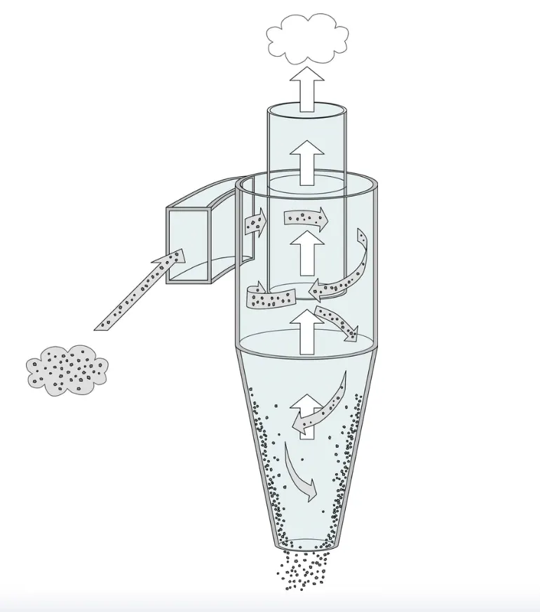
- The solids to be separated are suspended in a stream of gas (usually air). Such a feed is introduced tangentially at a very high velocity so that rotary movement takes place within the vessel. The centrifugal force and vortexing throw the solids to the walls.
- As the speed of air diminishes, the particles fall to the conical base and are discharged through the solid outlet. The fluid (air) can escape from the central outlet at the top.
- It is used to separate solids from gases.
- It is also used for the size separation of solids in liquids.
- It is used for separating heavy or coarse fractions from fine dust.
- Cyclone separators are also used for the size separation of solids suspended in a liquid such as water. Such separators are known as wet or liquid cyclones. One such apparatus used for this purpose is the Dorrclone.
Empirical Model for Cyclone efficiency:
1. IOZIA AND LEITH MODEL:
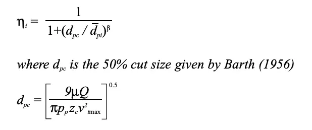
- Iozia and Leith's (1990) logistic model is a modified version of Barth's (1956) model which is developed based on force balance. The model assumes that a particle carried by the vortex endures the influence of two forces: a centrifugal force, Z, and flow resistance, W. Core length, zc, and core diameter, dc, are given as
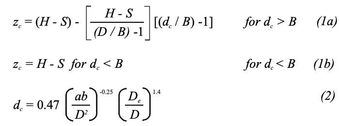
- The addition made by Iozia and Leith on the original Barth (1956) model is the core length zc and slope parameter β expression which is derived based on the statistical analysis of experimental data of cyclones with D = 0.25 m. The collection efficiency ηi of particle diameter dpi can be calculated from
2. LI AND WANG MODEL:
- 2 LI AND WANG MODEL The Li and Wang (1989) model includes particle bounce or re-entrainment and turbulent diffusion at the cyclone wall. A two-dimensional analytical expression of particle distribution in the cyclone is obtained. Li and Wang's model was developed based on the following assumptions:
- The radial particle velocity and the radial concentration profile are not constant, for uncollected particles within the cyclones.
- Boundary conditions with the consideration of turbulent diffusion coefficient and particle bounce re-entrainment on the cyclone wall are:
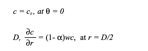
- The tangential velocity is related to the radius of the cyclone by uRn = constant.
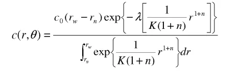
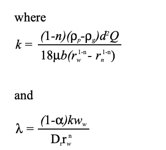
The concentration distribution in a cyclone is given as:
3. KOCH AND LICHT MODEL:
- Koch and Licht's (1977) collection theory recognized the inherently turbulent nature of cyclones and the distribution of gas residence times within the cyclone. Koch and Licht describe particle motion in the entry and collection regions with the additional following assumptions:
- The tangential velocity of a particle is equal to the tangential velocity of the gas flow, i.e. there is no slip in the tangential direction between the particle and the gas.
- The tangential velocity is related to the radius of the cyclone by uRn = constant.
A force balance and an equation on the particle collection yield the grade efficiency ηi.
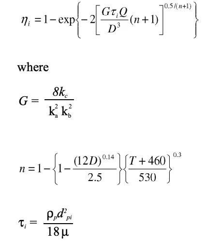
- G is a factor related to the configuration of the cyclone, n is related to the vortex and τ is the relaxation term.
4. LAPPLE MODEL:
- Lapple's (1951) model was developed based on force balance without considering the flow resistance. Apple assumed that a particle entering the cyclone is evenly distributed across the inlet opening.
- The particle that travels from the inlet half-width to the wall in the cyclone is collected with 50% efficiency. The semi-empirical relationship developed by Lapple (1951) to calculate a 50% cut diameter, DPC, is
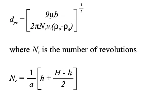
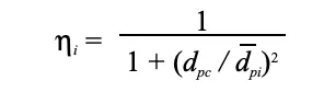
The efficiency of collection of any size of a particle is given by
PROCEDURE:
- Import the given geometry in SpaceClaim.
- Extract the fluid volume from the geometry.
- Suppress the given geometry for physics.
Mesh:
- Here, the domain is meshed using a cut-cell approach to improve accuracy and mesh quality.
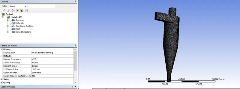
- Named selections are assigned to identify the inlets and outlets of the domain.
Setting up physics:
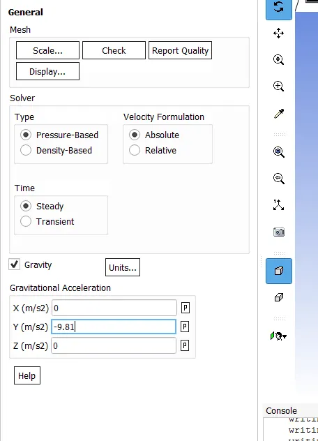
- Pressure-based, steady-state solver. Gravity = 9.81 m/s2
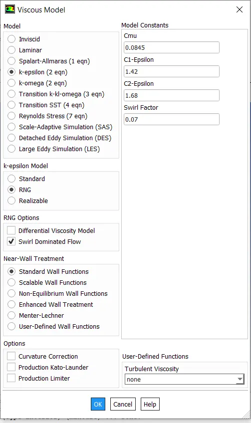
- Model: K-Epsilon -> RNG, swirl Dominated flow
- Model: Discrete Phase Model -> Interaction with continuous phase, update DPM sources every flow iteration, Max no of steps -> Create Injections
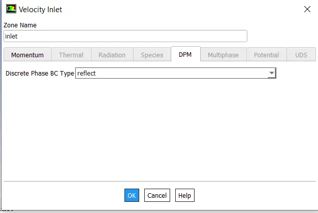
- Boundary Conditions: Inlet -> Velocity, DPM = reflect, Outlet top -> DPM = escape, Outlet bottom -> DPM = trap, walls -> DPM = reflect
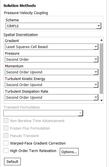
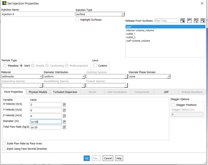
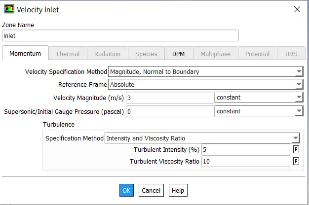
- Initialization: Standard initialization
- Run the simulation: Enter no iterations, run the simulation
RESULT:
CASE 1:
1. V= 3m/s, D= 1e-6m
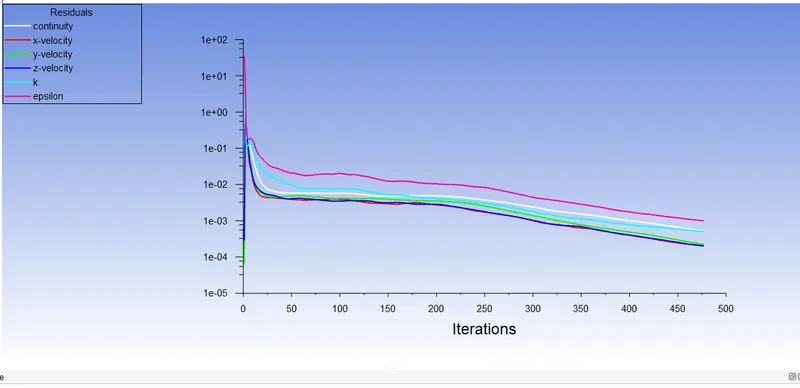
- Residual:
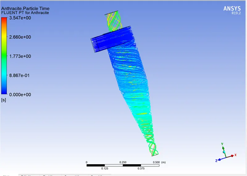
- Particle Resident Time & Separation Efficiency:
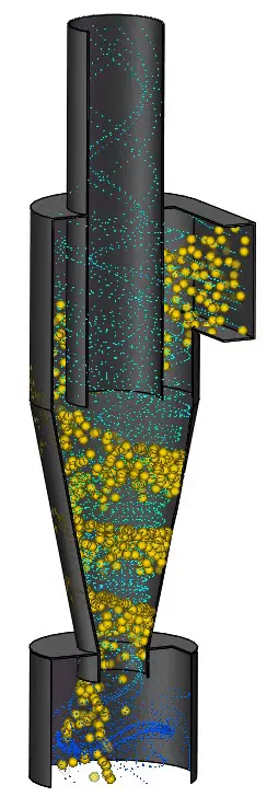
- Vortex Region:
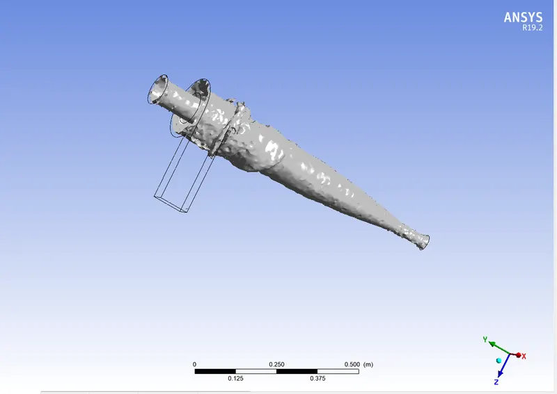
- Separation Efficiency = 271/450 = 60.12%
2. V= 3m/s, D= 2e-6m
- Residual:
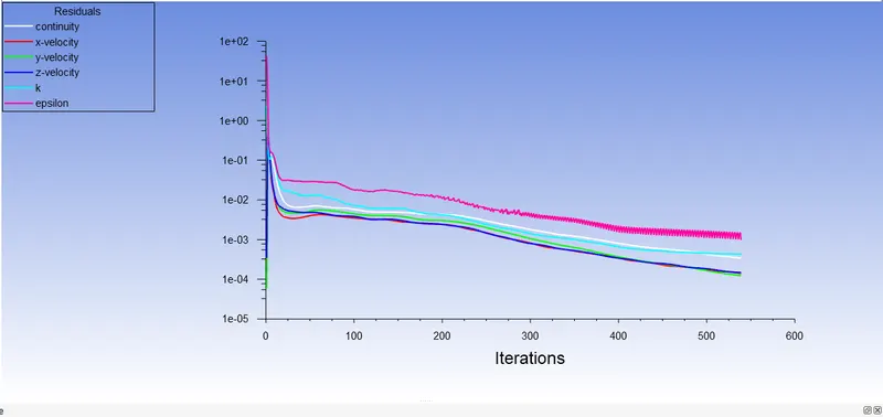
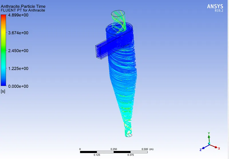
- Particle Resident Time & Separation Efficiency:
- Pressure Contour & Pressure Drop:
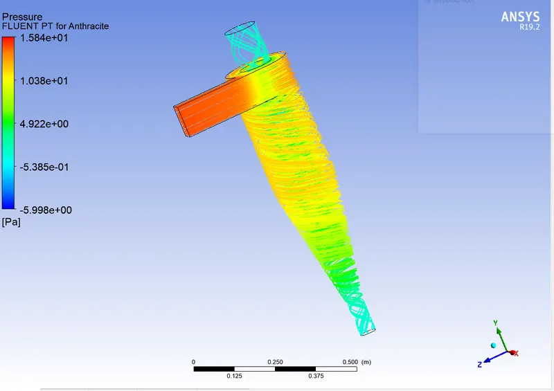
- Vortex Region:
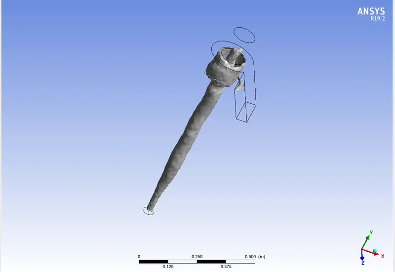
- Separation Efficiency = (Trapped/Tracked)*100 = 60.69%
3. V= 3m/s, D= 3e-6m
- Residual:
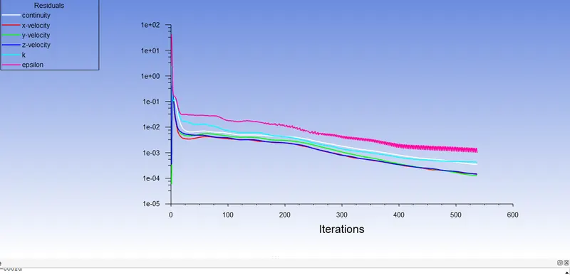
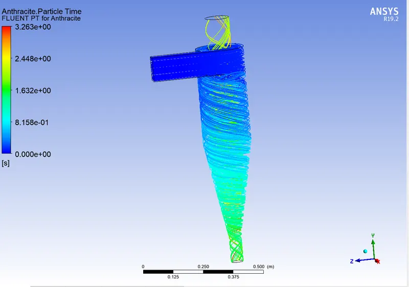
- Particle Resident Time & Separation Efficiency:
- Pressure Contour & Pressure Drop:
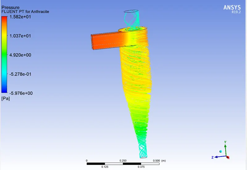
- Vortex Region:
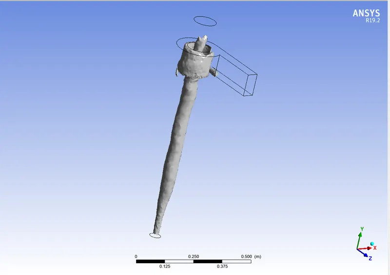
- Separation Efficiency = (Trapped/Tracked)*100 = 64.97%
4. V= 3m/s, D= 4e-6m
- Residual:
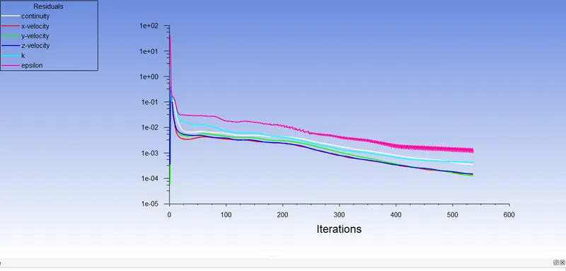
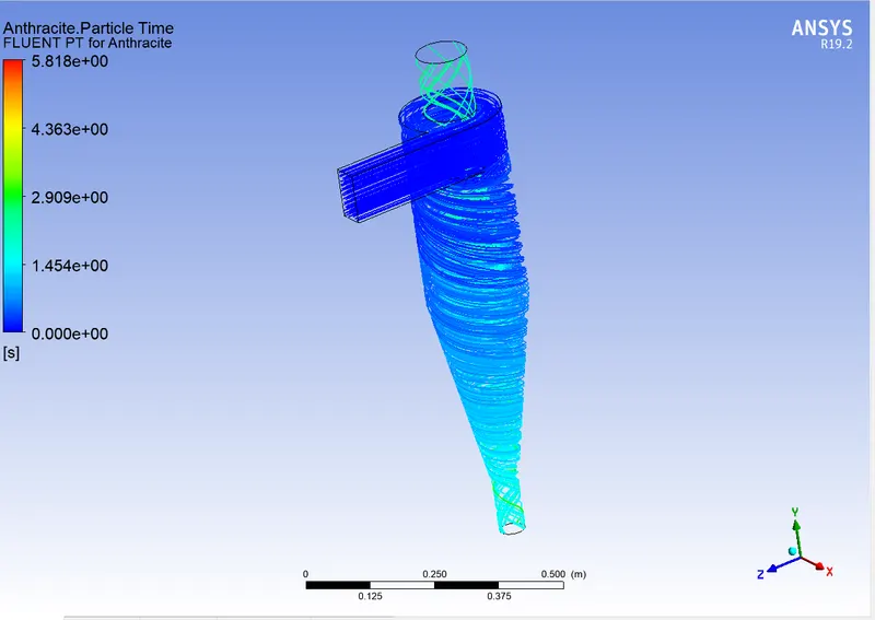
- Particle Resident Time & Separation Efficiency:
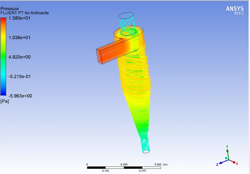
- Pressure Contour & Pressure Drop:
- Vortex Region:
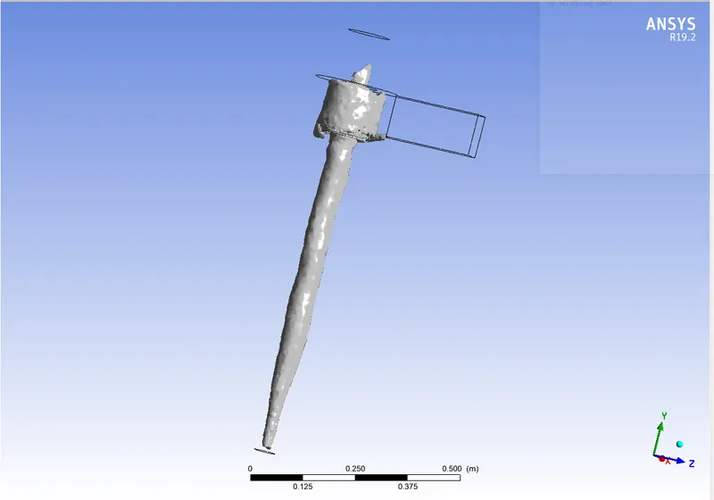
- Separation Efficiency = (Trapped/Tracked)*100 = 68.24%
5. V= 3m/s, D= 5e-6m
- Residual:
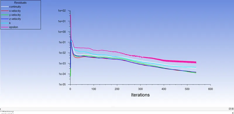
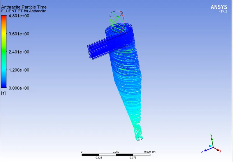
- Particle Resident Time & Separation Efficiency:
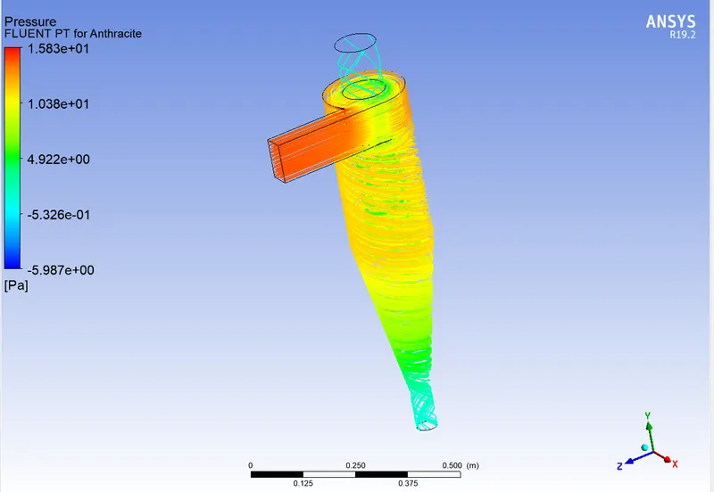
- Pressure Contour & Pressure Drop:
- Vortex Region:
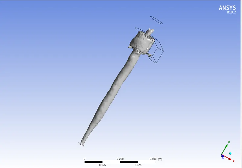
- Separation Efficiency = (Trapped/Tracked)*100 = 71.11%
CASE 2:
1. V= 1m/s, D= 5e-6m
- Residual:
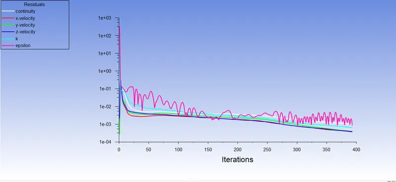
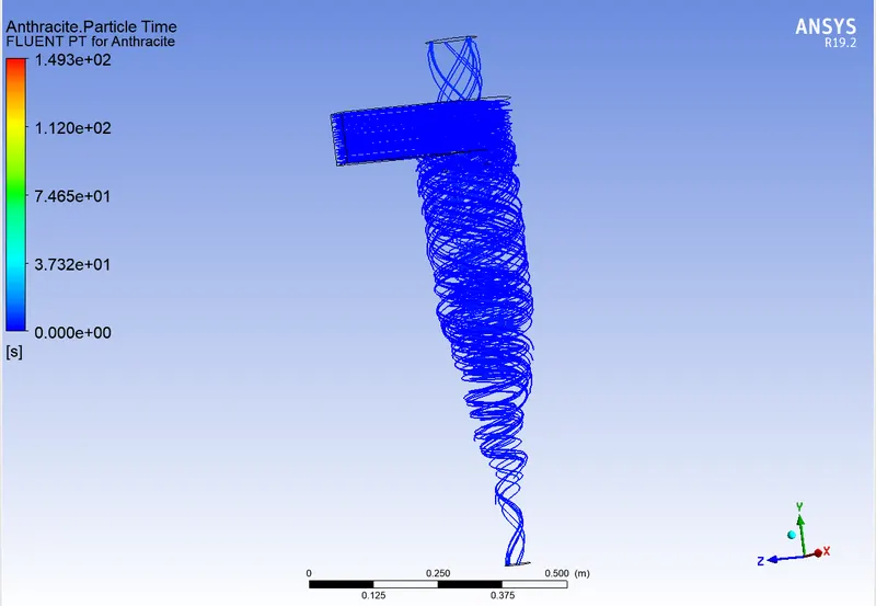
- Particle Resident Time & Separation Efficiency:
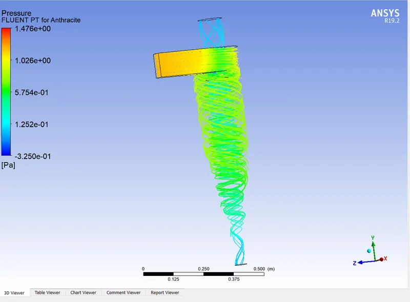
- Pressure Contour & Pressure Drop:
- Vortex Region:
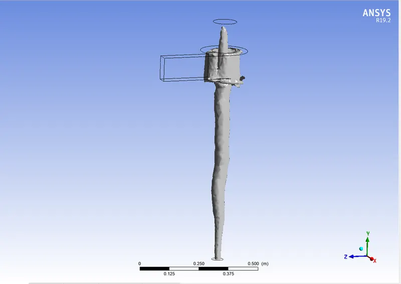
- Separation Efficiency = (Trapped/Tracked)*100 = 60.47%
2. V= 2m/s, D= 5e-6m
- Residual:
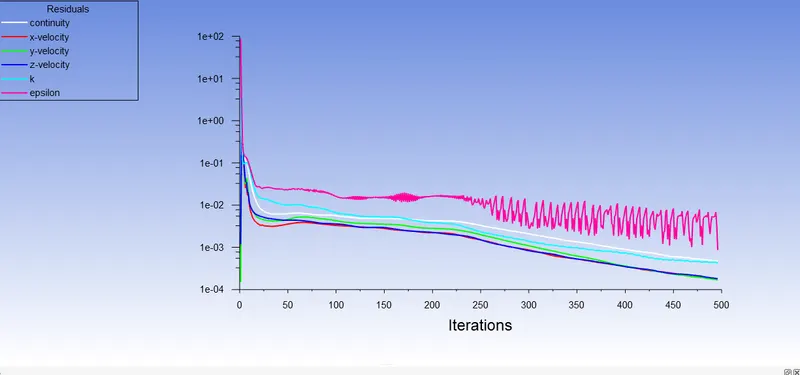
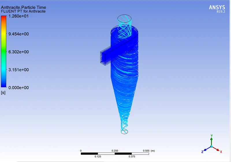
- Particle Resident Time & Separation Efficiency:
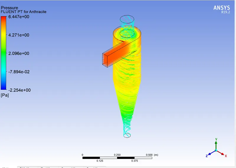
- Pressure Contour & Pressure Drop:
- Vortex Region:
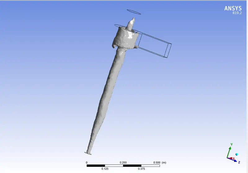
- Separation Efficiency = (Trapped/Tracked)*100 = 62.36%
3. V= 3m/s, D= 5e-6m
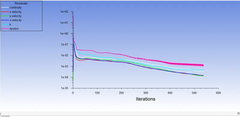
- Residual:
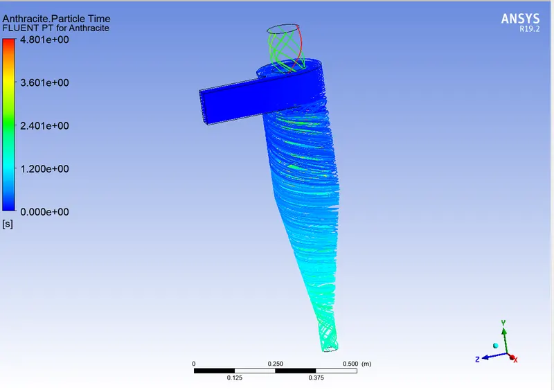
- Particle Resident Time & Separation Efficiency:
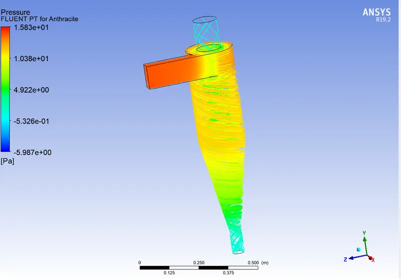
- Pressure Contour & Pressure Drop:
- Vortex Region:
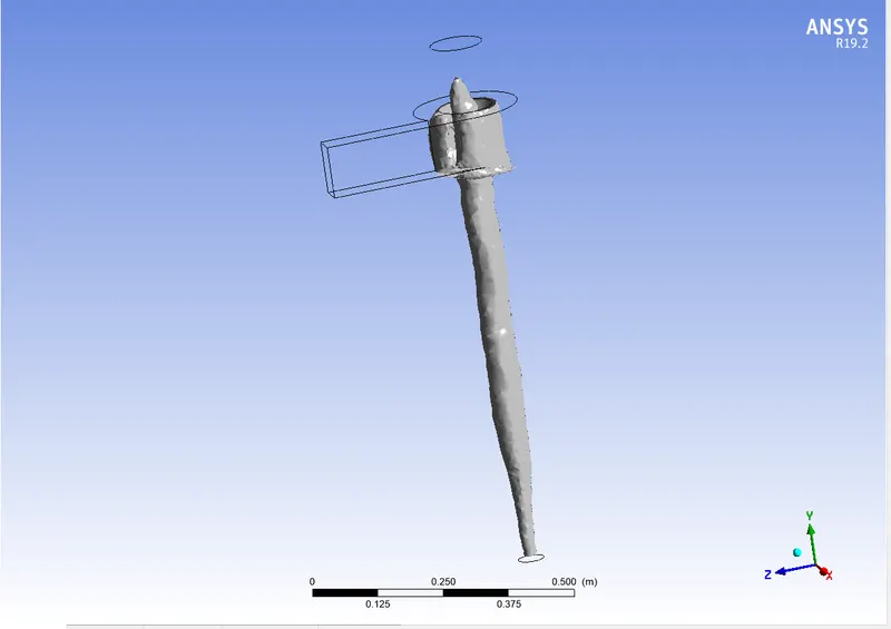
- Separation Efficiency = (Trapped/Tracked)*100 = 65.93%
4. V= 4m/s, D= 5e-6m
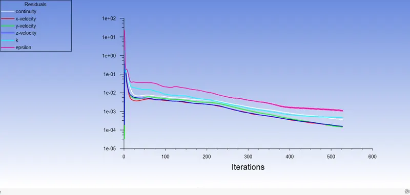
- Residual:
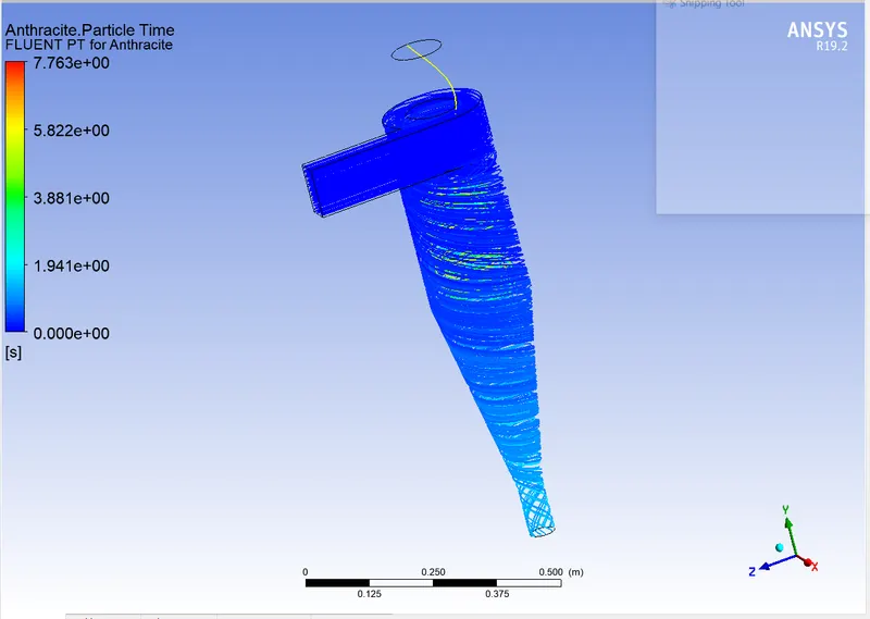
- Particle Resident Time & Separation Efficiency:
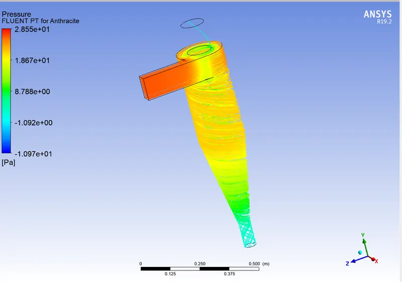
- Pressure Contour & Pressure Drop:
- Vortex Region:
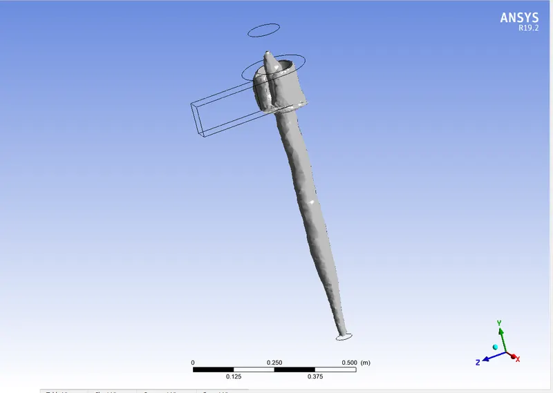
- Separation Efficiency = (Trapped/Tracked)*100 = 67.73%
5. V= 5m/s, D= 5e-6m
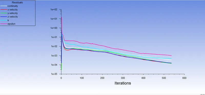
- Residual:
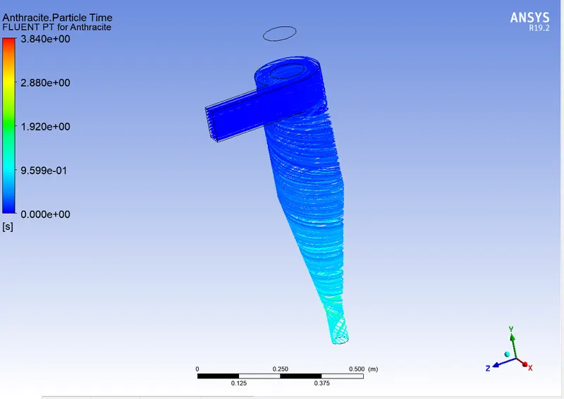
- Particle Resident Time & Separation Efficiency:
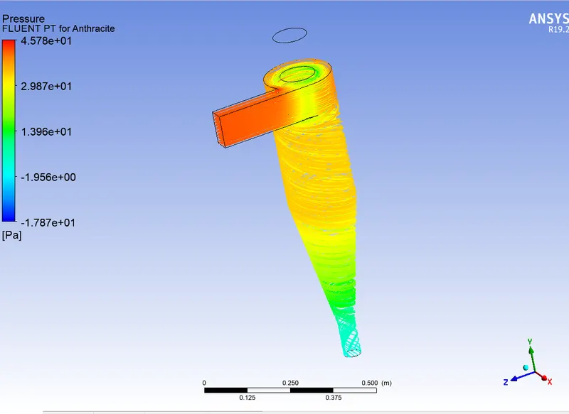
- Pressure Contour & Pressure Drop:
- Vortex Region:
- Separation Efficiency = (Trapped/Tracked)*100 = 73.81%
CONCLUSION:
- In this case, with decreases in particle size, cyclone separators of the same size and configuration become less effective.
- The particulate flow velocity has a discrete correlation with the cyclone separator's efficiency. High-velocity processes result in greater efficiency.
- Only the particulate velocity affects the pressure drop. The pressure difference between the inlet and outlet pressures rises as the velocity rises.
- The amount of time needed for convergence increases as the particle size and flow velocity both decrease. The maximum number of steps in the tracking parameters is therefore increased.