Week 3 - External flow simulation over an Ahmed body.
AIM:
- An external flow simulation over an Ahmed body.
OBJECTIVES:
- To describe Ahmed's body and its importance.
- To explain the reason for the negative pressure in the wake region.
- To explain the significance of the point of separation.
- To run the simulation for the velocity of 25 m/sec with the default air properties in fluent.
- To plot velocity and pressure contours and the drag coefficient plot for a refined case. ( For a velocity of 25m/sec, the drag coefficient should be around 0.33).
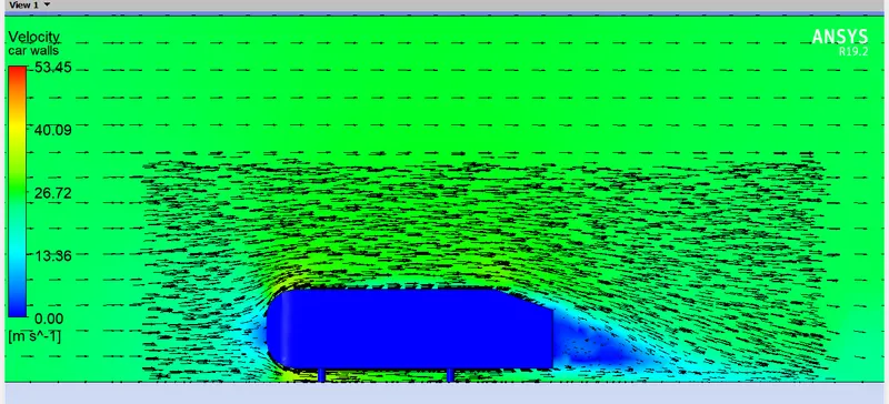
- Note: The vector plot clearly shows the wake region. Perform the grid independency test and provide the values of drag and lift with each case.
SOLUTION:
Ahmed's Body:
- Three main features of Ahmed's body were seen in the wake:
1. The A Recirculation region that is formed as the flow separates at the top of the vertical back surface of the model.
2. The B recirculation region is formed due to the separation at the base of the model.
3. The C-pillar vortices that form as the vorticity in the side boundary layers roll up over the slant edges.
- The wake region was shown to be highly dependent on slant angle. For slant angles less than 12°, the flow remains attached over the slant. The flow is essentially two-dimensional and has low drag. Between 12° and 13°, the flow becomes much more three-dimensional as the C-pillar vortices form. These reach maximum strength at 30°. The drag increases significantly as the low-pressure cores act on the rear surfaces. Past 30° the flow separates fully off the slant. This results in a sudden decrease in drag and weaker C-pillar vortices.
- Effect of Aspect Ratio: Venning et al (7) showed that the aspect ratio of the rear slant had a significant effect on the wake. The wider bodies ceased to reattach at slant angles of 25°, suggesting that the critical angle is lower as the aspect ratio increases. They also provide vortex core locations from experimental data that can be used for validation (8).
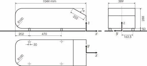
- Description of the test case: The Ahmed body (Fig. 1) was first defined and its characteristics were described in the experimental work Ahmed (1). Two configurations with slant angles of 25° and 35° are considered as a test case. For these configurations, detailed LDA Measurements have been performed by Becker, Lienhart, and Stoots (2,3) in the LSTM low-speed wind tunnel with a cross-section of 1.87*1.4 m2 (width * height) with a bulk velocity of 40 m/s. The test section of the wind tunnel was 3/4 open ( only ground plate present). The distance between the body and the plate representing the ground is 50 mm. In the experiment performed by Ahmed [1], flow velocity was taken at 60 m/s, Reynolds number was 4.29 million based on model length.
Reference:https;//www.cfdonline.com/wiki/Ahmed body
The reason for the negative pressure in the wake region
-
- It is difficult to navigate the flow around the Ahmed reference body. The vehicle's rear has a slant, which causes flow separation and counter-rotating vortices to form at the slant edges. When the slant angle is 30 degrees, the drag forces on Ahmed's Body are at their highest. For slant angles greater than this, the flow completely separates over the slant due to tje extreme pressure gradient between the slant and the roof.
- The flow still separates below this critical slant angle of 30 degrees, but the pressure difference between the side walls and the slant region is still strong enough to produce significant stream-wise vortices at the lateral slant edges. These cause the slant to move downward, primarily in the downstream area.
- The flow that separates at the upstream end of the slant can then be further coupled to the downstream as a result. There are several flow separations from the front to the back of the vehicle in the flow around Ahmed's body. The vehicle's drag is a result of the flow recirculation these flow detachments cause.
- A precise simulation of the wake flow and of the separation process is necessary for the accurate outcome of drag predictions because the location point at which the flow separates determines the size of the separation zone and, consequently, the drag force.
The significance of the point of separation:
- As the flow expands, an adverse pressure gradient is encountered, resulting in separation and an extended region of separated flow. The dividing streamline is the portion of the flow that divides the recirculating flow from the flow through the center.
- The reattachment point refers to the location where the dividing streamline reattaches to the wall. The flow eventually reaches equilibrium as it moves further downstream, and there is no longer any reverse flow.
- The remnants of the boundary layer that separate into a shear layer change the potential flow and pressure field outside by creating a separated flow region between the shear layer and the surface. The modification of the pressure field causes an increase in pressure drag in the case of airfoils.
Simulation of Ahmed's body:
- The geometry of Ahmed's body is shown below,

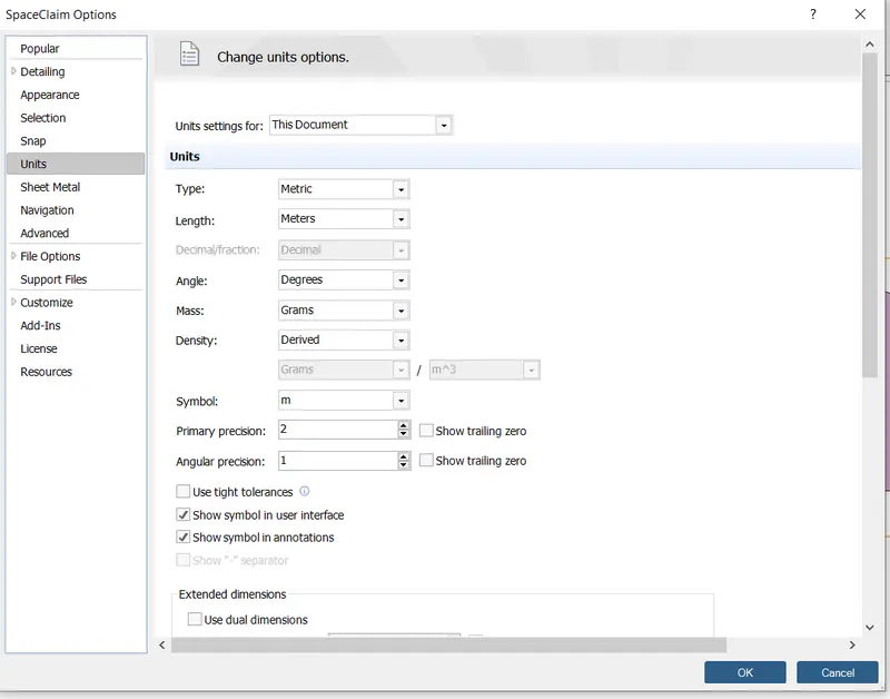
- Load the Ahmed body model into SpaceClaim and convert the units from millimeters to meters.
- Creating the rectangular box around the body, As the body is perfectly symmetric, we can run the simulation by considering the only half body. once the enclosure is done, we can create another enclosure closely around Ahmed's body so that we can refine the mesh in that enclosure and still keep the total cell countless.
- In the meshing, we can assign the named selection for the inlet, outlet, symmetry wall, and car wall, we can use the different types of meshing processes for this model.
Here we follow three stages,
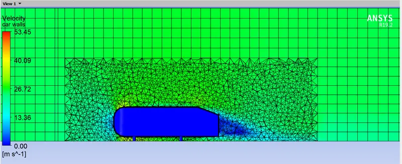
1. Meshing will be done for the outer enclosure chosen as a method of the Multizone and this will create the Hexa mesh, The element size under this is 0.1m.
2. For the inner enclosure we choose the body sizing method to make more refinement, the element size we use for this is 0.032m.
3. Next we select the face sizing method to select the legs of the body to capture them with better refinement, we take the element length as 0.005m.
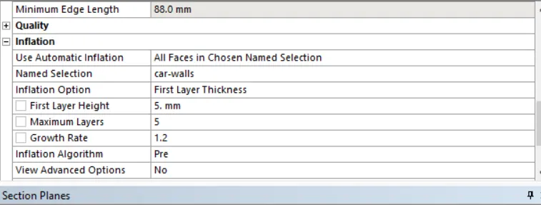
4. Then to capture the flow over the body we make the inflation layer which helps us in capturing the flow very finer way and the mesh will also be captured along the body perfectly. We take the number of inflation layers as 6, Total thickness value as 0.0036.
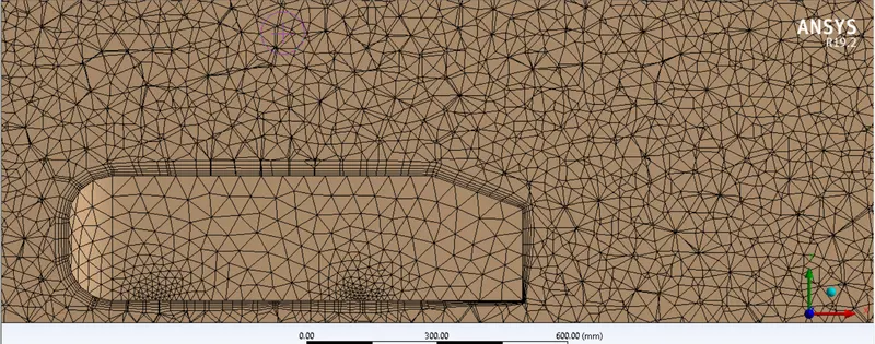
- Detail of mesh:

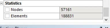
- Total no of cell counts:
- Reference values:
SETUP:
Solver type: Density-based
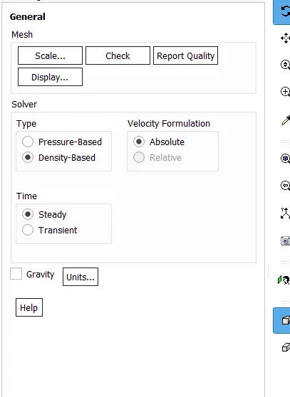
Check the Energy equation
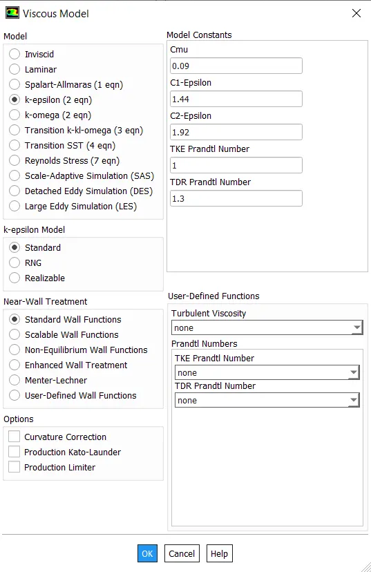
Turbulent Model : K-Epsilon
Fluid Material: Air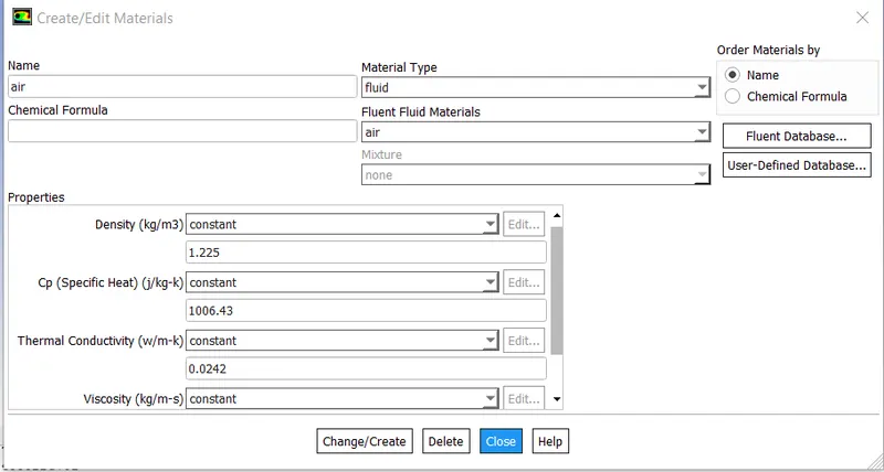
Boundary Conditions:
Inlet velocity : 25m/s
Outlet pressure : 0 pa
Symmetry : For side walls
wall: Bottom
Creating a surface plane to observe the counters.
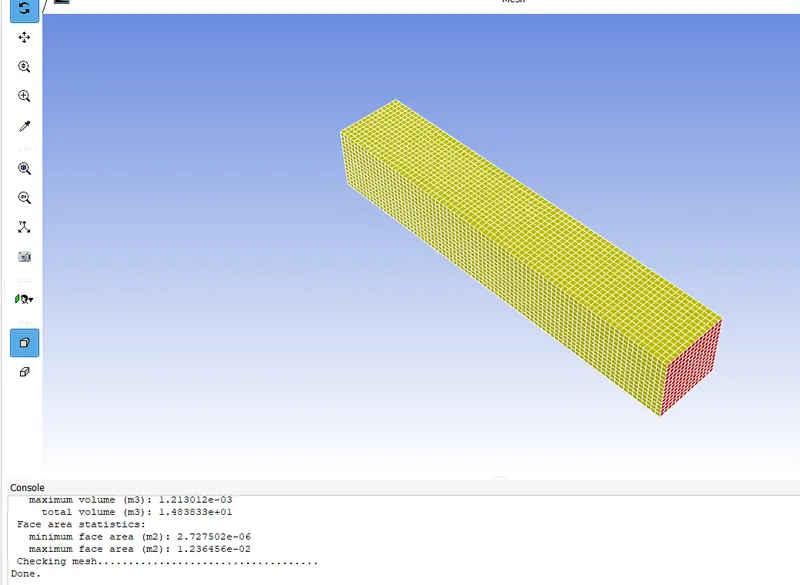
- Checking mesh
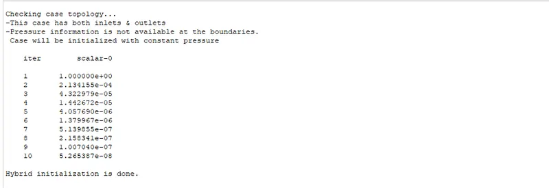
- Initialize the condition using a hybrid,
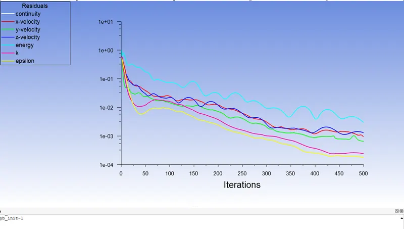
- Run the simulation for 500 iterations.
Results:
1. Residual plot:
- The plane along the z-axis gets the velocity and pressure variation.
2. Velocity contour plot:
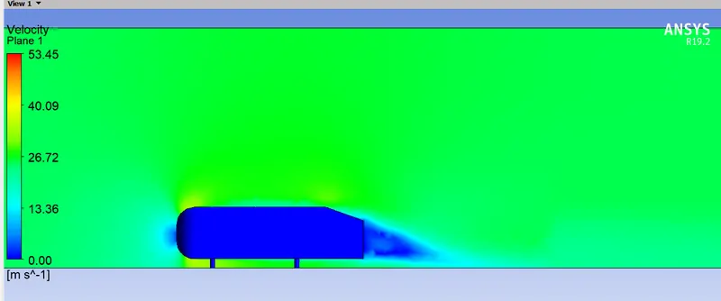
velocity Mesh Mode:
Velocity Vector Mode:
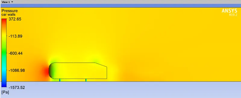
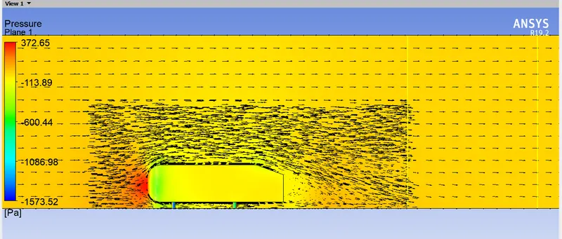
3. Pressure contour plot:
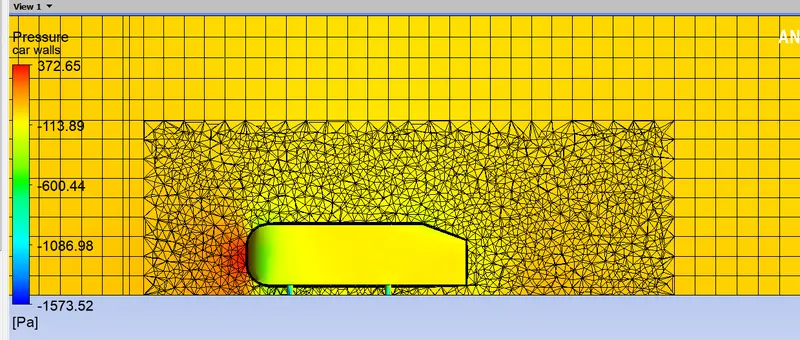
Pressure Mesh Mode:
Pressure Vector Mode:
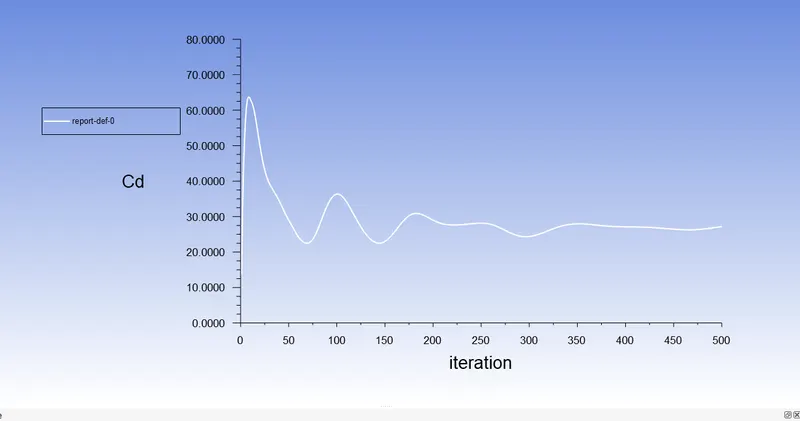
- DRAG COEFFICIENT:
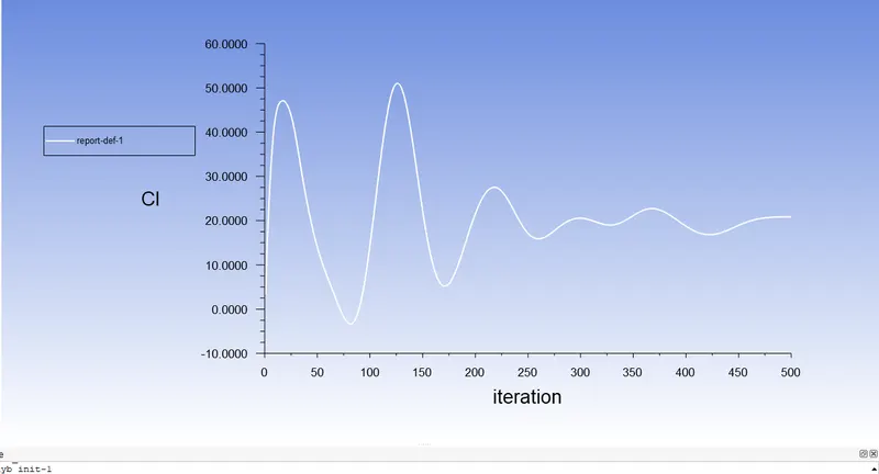
- DRAG FORCE:
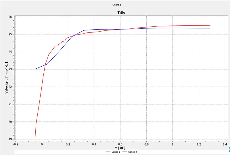
- Velocity Variation:
RESULT:
For,
Inlet Velocity : 25m/s
Outlet pressure : 0 pa
- Total no of cells =188831
- Total no of Cd = 0.384
- Total no of Ci = 0.241
- From the above table, the refinement of the mesh drag coefficient approaches closure to the analytical values that are because more cells are assigned at the boundary layer which results in more accurate results of drag coefficients.
CONCLUSION:
- The Ahmed body's frontal region experiences high pressure because of the air's loss of kinetic energy.
- The flow separation is caused by the model's geometry, an adverse pressure gradient is produced close to the wake regions.
- In changes of pressure gradient as a result of flow separation, When turn changes the drag and lifts coefficients.
- Detachment of the fluid should occur farther from the body in order to reduce the size of the wake region, which can be accomplished by increasing the slant angle.