Week 8 - Simulating Cyclone separator with Discrete Phase Modelling
Aim:- To perform analysis on cyclone separator and calculate the separation efficiency and pressure drop.
Objective:-
- To write a few words about any four empirical models used to calculate the cyclone separator efficiency.
- To perform an analysis on a given cyclone separator model by varying the particle diameter from 1 μm to 5 μm and calculate the separation efficiency in each case. Discuss the results. [Use both the velocity's as 3m/sec.]
- To perform an analysis on a given cyclone separator model by varying the particle velocity from 1 m/sec to 5 m/sec and calculate the separation efficiency and pressure drop in each case. Discuss the results. [Use particle diameter size as 5 μm for all cases & keep flow velocity same as particle velocity]
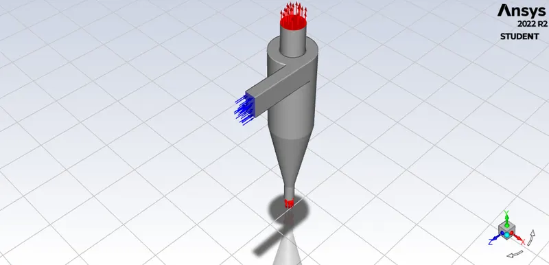
Boundary Conditions:-
Inlet and wall:- Reflect
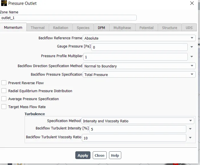
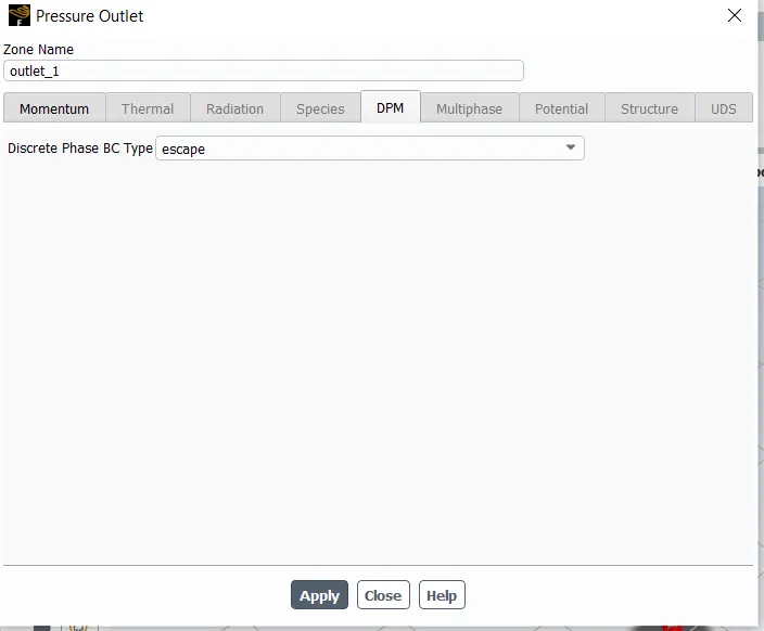
Outlet(Top):- Escape
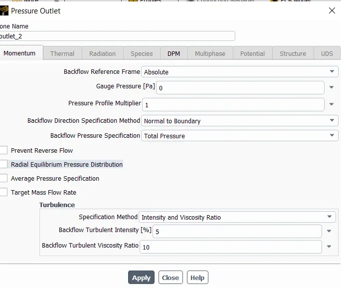
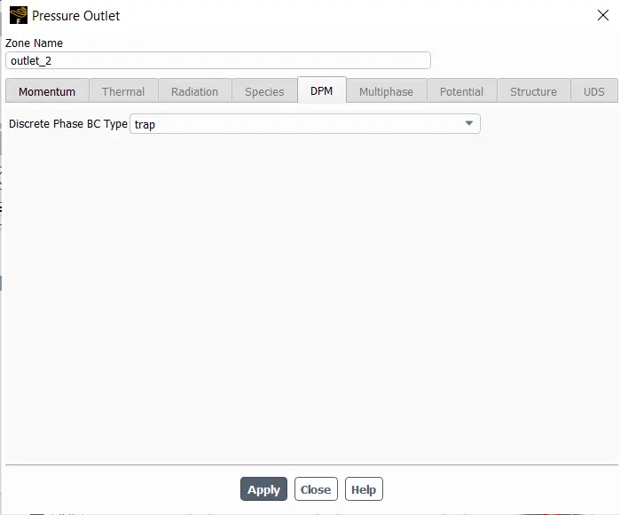
Outlet(Bottom/dustbin) - Trap
1. Few words about any four empirical models used to calculate the cyclone separator efficiency.
Cyclone Seperator: Cyclonic or particle separation is a process used to extract specifically identified particulates from a fluid stream (air, gas or liquid). This cyclone separator design forgoes filters, and instead relies on vortex separation for the operation. These applications vary depending on the fluid from which particles are removed.
Applications:
- Sawmills to remove sawdust
- Oil refineries
- Kiln preheaters
- Vacuum cleaners
- Extraction hoods
- High-pressure washing devices
- Lubricating fluid
- Industrial water treatment
Iozia and Leith (1990) logistic model is a modified version of Barth (1956) model which is developed based on force balance. The model assumes that a particle carried by the
vortex endures the influence of two forces: a centrifugal force, Z, and a flow resistance, W. Core length, zc, and core diameter,dc, are given as
The addition made by Iozia and Leith on the original Barth (1956) model are the core length zc and slope parameter β expression which is derived based on the statistical analysis of
experimental data of cyclone with D = 0.25 m. The collection efficiency ηi of particle diameter dpi can be calculated from
- Lia and wang Model:
The Li and Wang (1989) model includes particle bounce or re-entrainment and turbulent diffusion at the cyclone wall. A two-dimensional analytical expression of particle distribution
in the cyclone is obtained. Li and Wang model was developed based on the following assumptions:
- The radial particle velocity and the radial concentration profile are not constant, for uncollected particles within the cyclones.
- Boundary conditions with the consideration of turbulent diffusion coefficient and particle bounce re-entrainment on the cyclone wall are:c=c0,at θ=0
- The tangential velocity is related to the radius of cyclone by: uRn = constant.
- The resultant expression of the collection efficiency for particle of my size is given as
- Koch and Licht Model:
Koch and Licht (1977) collection theory recognized the inherently turbulent nature of cyclones and the distribution of gas residence times within the cyclone. Koch and Licht
describe particle motion in the entry and collection regions with the additional following assumptions:
• The tangential velocity of a particle is equal to the tangential velocity of the gas flow, i.e. there is no slip in the tangential direction between the particle and the gas.
• The tangential velocity is related to the radius of cyclone by: uRn = constant.
A force balance and an equation on the particles collection yields the grade efficiency ηi
G is a factor related to the configuration of the cyclone,n is the related to vortex and τ is the relaxation term.
- Lapple Model:
Lapple (1951) model was developed based on force balance without considering the flow resistance. Lapple assumed that a particle entering the cyclone is evenly distributed across the inlet opening. The particle that travels from inlet half width to the wall in the cyclone is collected with 50% efficiency. The semi empirical relationship developed by Lapple (1951) to
calculate a 50% cut diameter, dpc,is
The efficiency of collection the any size of particle is given by
Cyclone Seperator simulation :
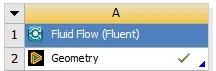
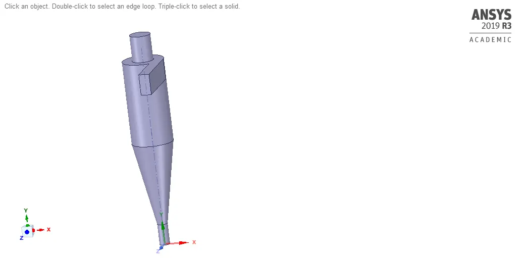
1. Geometry setup :
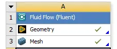
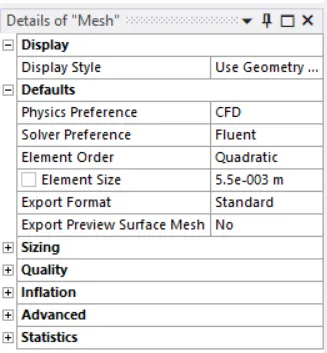
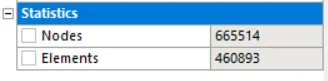
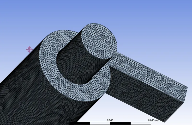
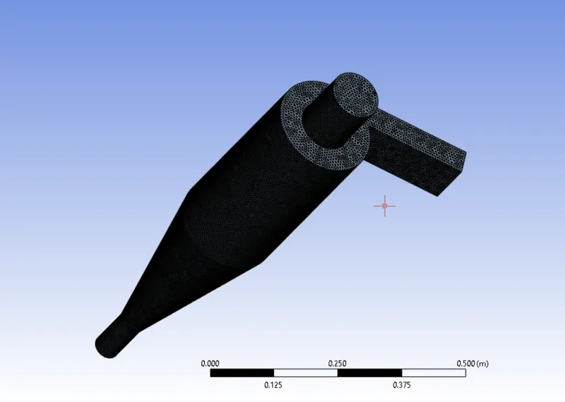
2. Meshing up geometry :
3. Setting up geometry :
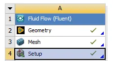
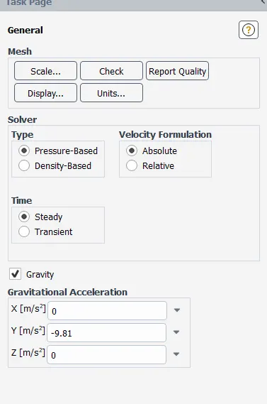
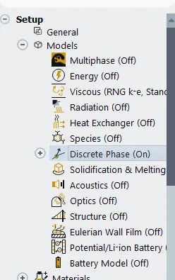
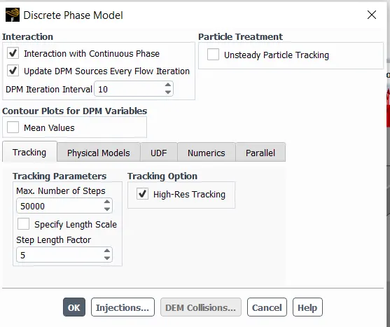
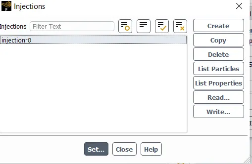
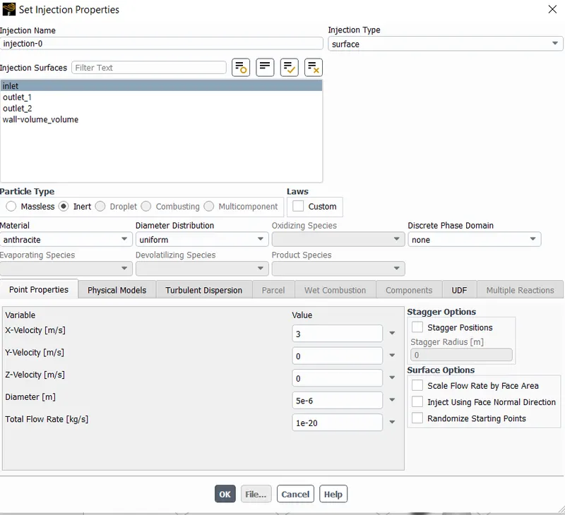
Boundary Conditions :
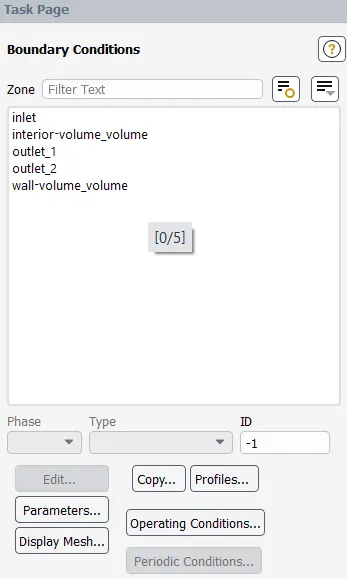
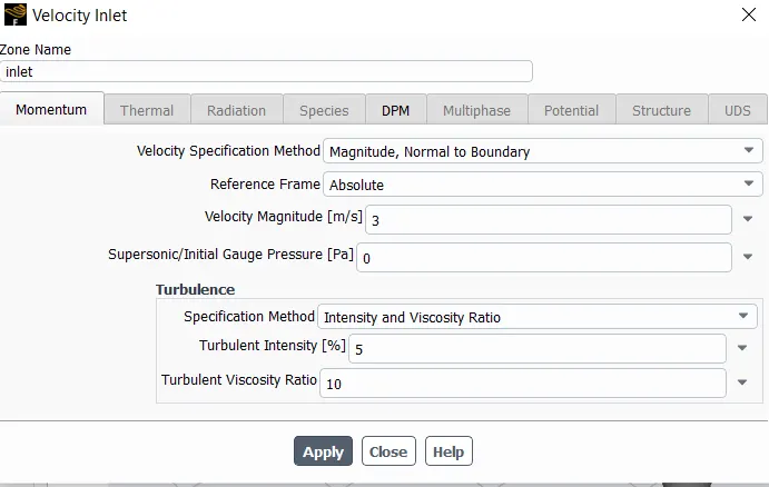
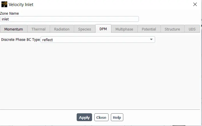
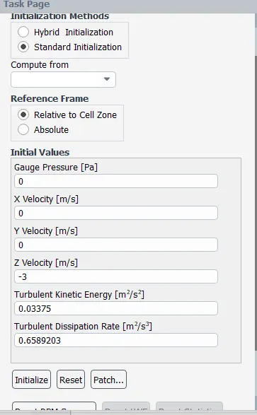
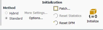
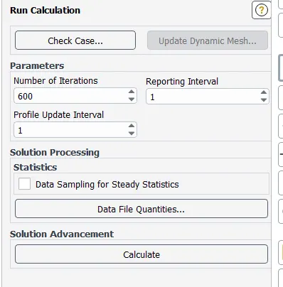
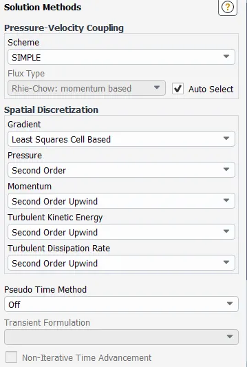
4. Solution and Results :
2. To perform an analysis on a given cyclone separator model by varying the particle diameter from 1 μm to 5 μm and calculate the separation efficiency in each case. Discuss the results. [Use both the velocity's as 3m/sec.]
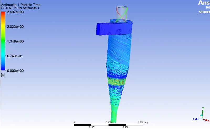
2a. Particle Diameter: 5 μm, Particle & Inlet Flow Velocity: 3m/s.
2b. Particle Diameter: 3 μm, Particle & Inlet Flow Velocity: 3m/s.
2c. Particle Diameter: 1 μm, Particle & Inlet Flow Velocity: 3m/s.
2a. Particle Diameter: 5 μm, Particle & Inlet Flow Velocity: 3m/s.
pressure at inlet:
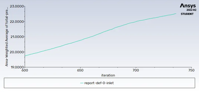
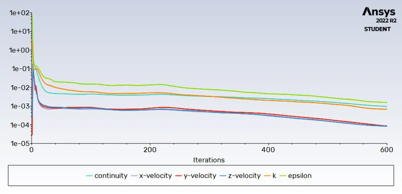
residuals graph:
pressure at outlet:
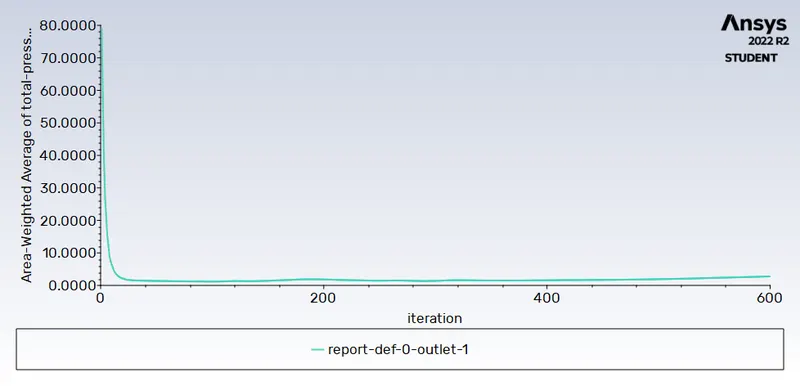

Seperation efficiency: Number of Particles escaped/Number of Particles Tracked
= 6/346 =1.73%
Animation link :
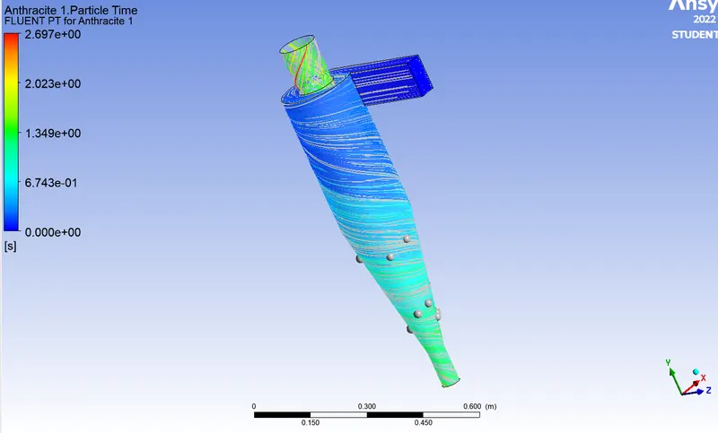
2b. Particle Diameter: 3 μm, Particle & Inlet Flow Velocity: 3m/s.
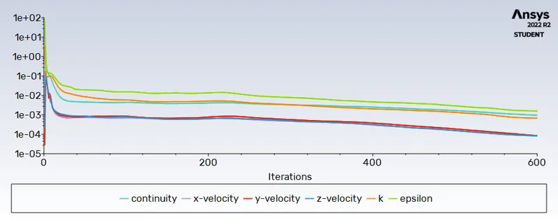
Residuals graph:
pressure at inlet:
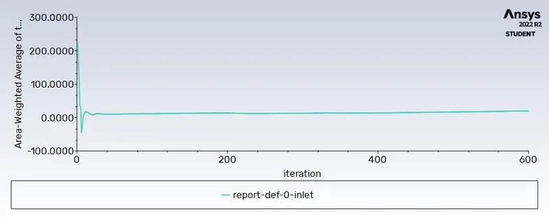
pressure at outlet:
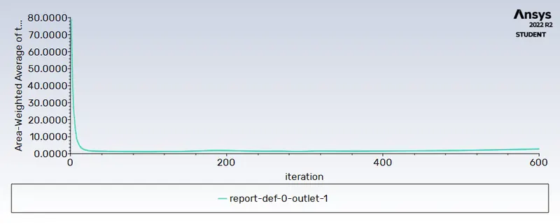

Seperation efficiency: Number of Particles escaped/Number of Particles Tracked
= 14/346 = 4.04%
Animation link :
https://youtu.be/kD6EjxQ6-iA
2c. Particle Diameter: 1 μm, Particle & Inlet Flow Velocity: 3m/s.
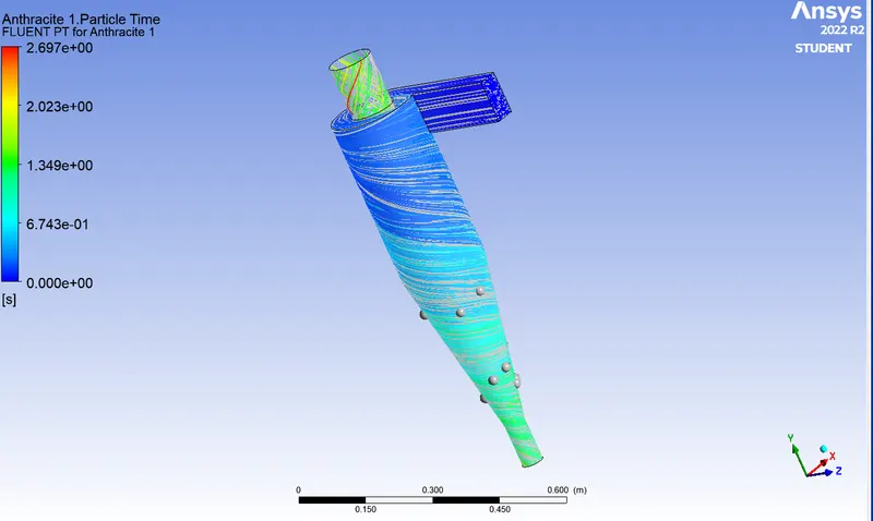
Residuals graph:
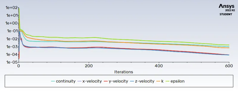
pressure at inlet:
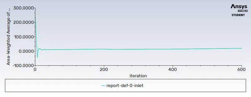
pressure at outlet:
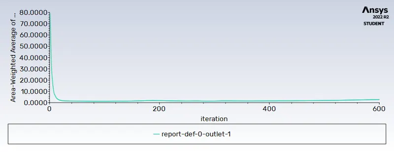

Seperation efficiency: Number of Particles escaped/Number of Particles Tracked
= 15/346 = 4.33%
Animation link :
https://youtu.be/SX1fr-8ktt8
3. To perform an analysis on a given cyclone separator model by varying the particle velocity from 1 m/sec to 5 m/sec and calculate the separation efficiency and pressure drop in each case. Discuss the results. [Use particle diameter size as 5 μm for all cases & keep flow velocity same as particle velocity]
3a. Particle Diameter: 5 μm, Particle & Inlet Flow Velocity: 1m/s.
3b. Particle Diameter: 5 μm, Particle & Inlet Flow Velocity: 3m/s.
3c. Particle Diameter: 5 μm, Particle & Inlet Flow Velocity: 5m/s.
3a. Particle Diameter: 5 μm, Particle & Inlet Flow Velocity: 1m/s.
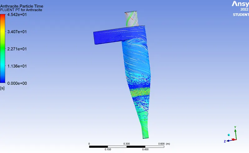
residuals graph:
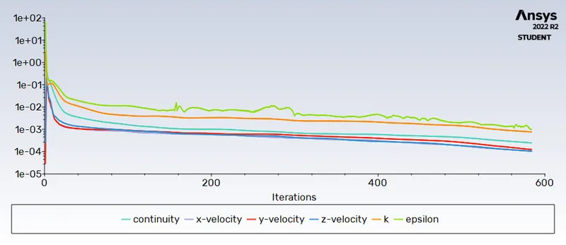
pressure at outlet:
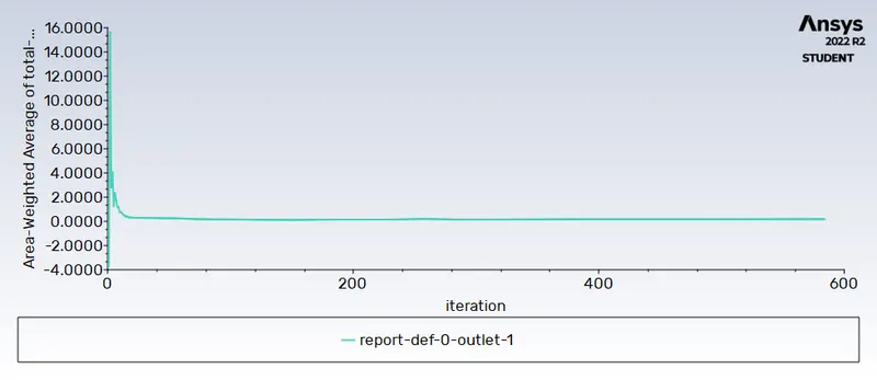
pressure at inlet:
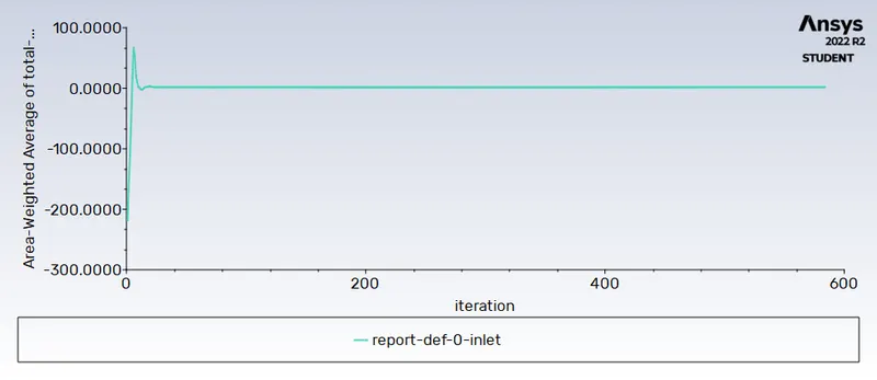

Seperation efficiency: Number of Particles escaped/Number of Particles Tracked
= 70/346 = 20.2%
Animation link :
3b. Particle Diameter: 5 μm, Particle & Inlet Flow Velocity: 3m/s.
pressure at inlet:
residuals graph:
pressure at outlet:
Seperation efficiency: Number of Particles escaped/Number of Particles Tracked
= 6/346 =1.73%
Animation link :
3c. Particle Diameter: 5 μm, Particle & Inlet Flow Velocity: 5m/s.
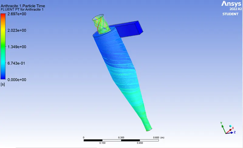
pressure at inlet:
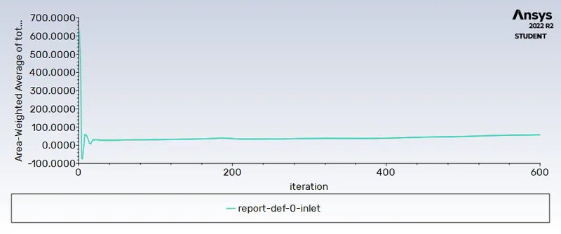
pressure at outlet:
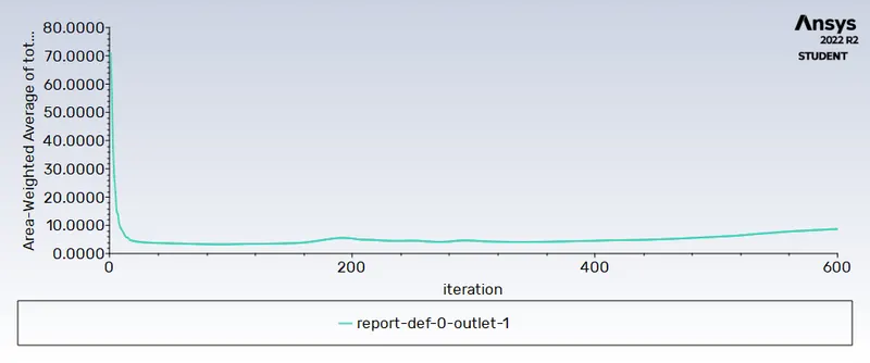
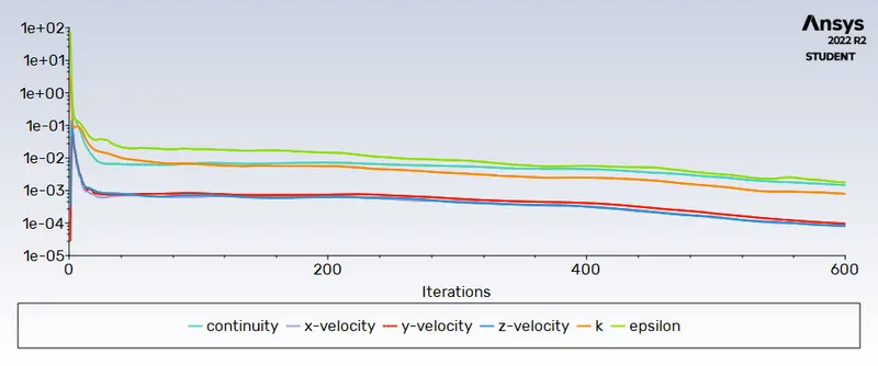
residuals graph:

Seperation efficiency: Number of Particles escaped/Number of Particles Tracked
= 30/346 = 17.3%
Animation link :
Conclusion :
The collection efficiency of cyclones varies as a function of particle size, density, and cyclone design. Cyclone efficiency will generally increase with the increase in particle size, density, inlet duct velocity, cyclone body length, number of gas revolutions in the cyclone, the ratio of cyclone body diameter to gas exit diameter, inlet dust loading, smoothness of the cyclone inner wall.
The efficiency of the cyclone will decrease with an increase in the parameters such as gas viscosity, cyclone body diameter, gas exit diameter, gas inlet duct area, gas density, leakage of air into dust outlet.
With the increase in inlet velocity or particle size the efficiency increases.
The collection efficiency of the cyclone separator is related to the pressure drop across the cyclone. Here pressure drop is the indirect measure of the energy required for the gas to move the particles. Pressure drop is related to the inlet velocity of air and particle size.
Pressure drop occurs because of the following components:
1. Loss due to the expansion of gas in the cyclone chamber.
2. Loss due to rotational kinetic energy.
3. Loss due to wall frictional forces