Week 8 - Simulating Cyclone separator with Discrete Phase Modelling
Aim:- To perform analysis on cyclone separator and calculate the separation efficiency and pressure drop.
Objective:-
- To write a few words about any four empirical models used to calculate the cyclone separator efficiency.
- To perform an analysis on a given cyclone separator model by varying the particle diameter from 1 μm to 5 μm and calculate the separation efficiency in each case. Discuss the results. [Use both the velocity's as 3m/sec.]
- To perform an analysis on a given cyclone separator model by varying the particle velocity from 1 m/sec to 5 m/sec and calculate the separation efficiency and pressure drop in each case. Discuss the results. [Use particle diameter size as 5 μm for all cases & keep flow velocity same as particle velocity]
Boundary Conditions:-
Inlet and wall:- Reflect
Outlet(Top):- Escape
Outlet(Bottom/dustbin) - Trap
THEORY:
CYCLONE SEPARATOR:
Cyclone separators or simply cyclones are separation devices (dry scubbers) that use the principle of inertia to remove particulate matter from flue gases . Cyclone separators is one of many air pollution removers known as precleaners since they generally remove larger pieces of particulate matter. This prevents finer filtration methods from having to deal with large, more abrasive particles later on. In addition, several cyclone separators can operate in parallel, and this system is known as a multicyclone.
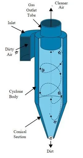
Cyclone separators work much like a centrifuge, but with a continuous feed of dirty air. In a cyclone separator, dirty flue gas is fed into a chamber. The inside of the chamber creates a spiral vortex, similar to a tornado. This spiral formation and the separation is shown in Figure . The lighter components of this gas have less inertia, so it is easier for them to be influenced by the vortex and travel up it. Contrarily, larger components of particulate matter have more inertia and are not as easily influenced by the vortex.
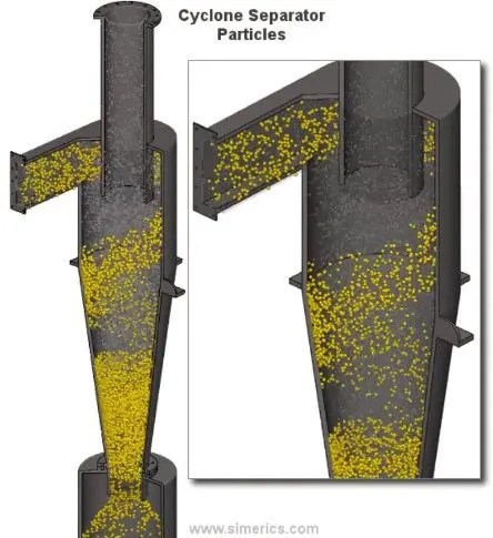
Since these larger particles have difficulty following the high-speed spiral motion of the gas and the vortex, the particles hit the inside walls of the container and drop down into a collection hopper. These chambers are shaped like an upside-down cone to promote the collection of these particles at the bottom of the container. The cleaned flue gas escapes out the top of the chamber.
Four empirical models used to calculate the cyclone separator efficiency :
1. IOZIA AND LEITH MODEL:
Iozia and Leith (1990) logistic model is a modified version of Barth (1956) model which is developed based on force balance. The model assumes that a particle carried by the vortex endures the influence of two forces: a centrifugal force,
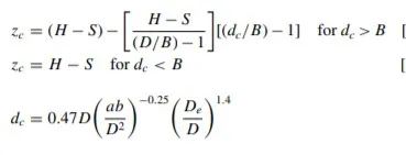
Z, and a flow resistance, W. Core length, zc, and core diameter ,dc are given as:
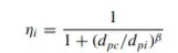
β is an expression for slope parameter derived based on the statistical analysis of experimental data of a cyclone with D = 170
0.25 m given as:

and dpc is the 50% cut size given by Barth:
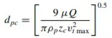
where core length, zc, and core diameter, dc, are given as,
2. LI AND WANG MODEL:
The Li and Wang [3] model includes particle bounce or reentrainment and turbulent diffusion at the cyclone wall. A twodimensional analytical expression of particle distribution in the cyclone is obtained. Li and Wang model was developed based 180 on the following assumptions:
The radial particle velocity and the radial concentration profile are not constant for uncollected particles within the cyclone.
Boundary conditions with the consideration of turbu185 lent diffusion coefficient and particle bounce reentrainment on the cyclone wall are:
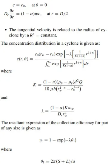
3. KOCH AND LICHT MODEL:
Koch and Licht [2] collection theory recognized the inherently turbulent nature of cyclones and the distribution of gas residence times within the cyclone. Koch and Licht described particle motion in the entry and collection regions with the ad- 200 ditional following assumptions:
- The tangential velocity of a particle is equal to the tangential velocity of the gas flow, i.e. there is no slip in the tangential direction between the particle and the gas.
- The tangential velocity is related to the radius of cy- 205 clone by: u Rn = constant.
A force balance and an equation on the particles collection yields the grade efficiency ηi:
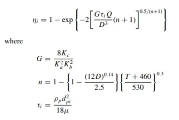
4. LAPPLE MODEL:
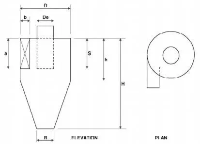
Lapple [1] model was developed based on force balance without considering the flow resistance. Lapple assumed that a par215 ticle entering the cyclone is evenly distributed across the inlet opening. The particle that travels from inlet half width to the wall in the cyclone is collected with 50% efficiency. The semi empirical relationship developed by Lapple [1] to calculate a 50% cut diameter, dpc, is:
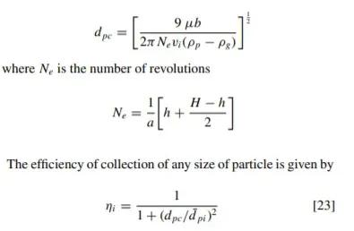
The collection efficiency of cyclones varies as a function of density, particle size and cyclone design.
Cyclone efficiency will generally increase with increases in particle size and/or density;
inlet duct velocity; cyclone body length;
number of gas revolutions in the cyclone; ratio of cyclone body diameter to gas exit diameter;
inlet dust loading;
smoothness of the cyclone inner wall.Similarly, cyclone efficiency will decrease with increases in the parameters such as gas viscosity;
cyclone body diameter; gas exit diameter;
gas inlet duct area; gas density;
leakage of air into the dust outlet.
The efficiency of a cyclone collector is related to the pressure drop across the collector.
This is an indirect measure of the energy required to move the gas through the system. The pressure drop is a function of the inlet velocity and cyclone diameter. Form the above discussion it is clear that small cyclones are more efficient than large cyclones. Small cyclones, however, have a higher pressure drop and are limited with respect to volumetric flow rates. Another option is arrange smaller cyclones in series and/or in parallel to substantially increase efficiency at lower pressure drops. These gains are somewhat compensated, however, by the increased cost and maintenance problems. Also these types of arrangements tend to plug more easily. When common hoppers are used in such arrangements, different flows through cyclones can lead to reentrainment problems.
GEOMETRY:
Fluid Volume extracted using SpaceClaim.
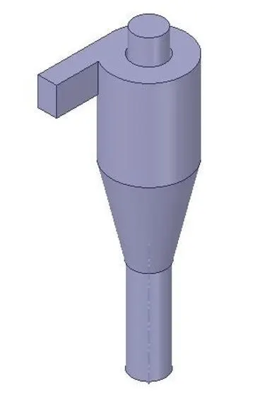
meshing:
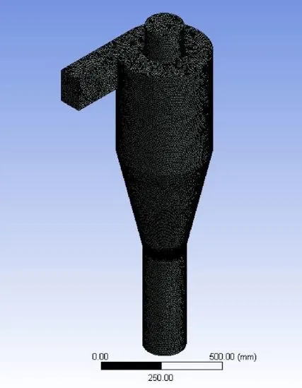
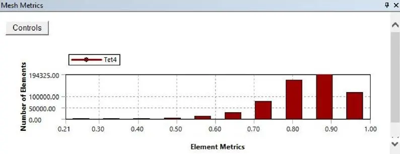
mesh metric:
setup and solution:
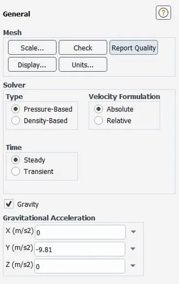
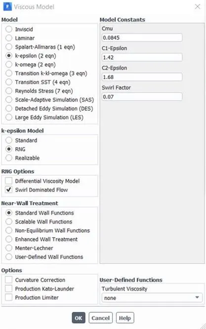
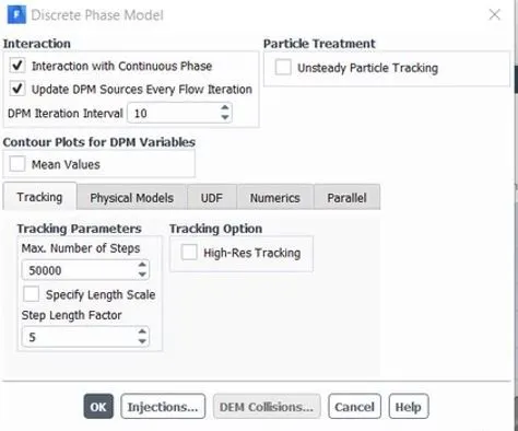
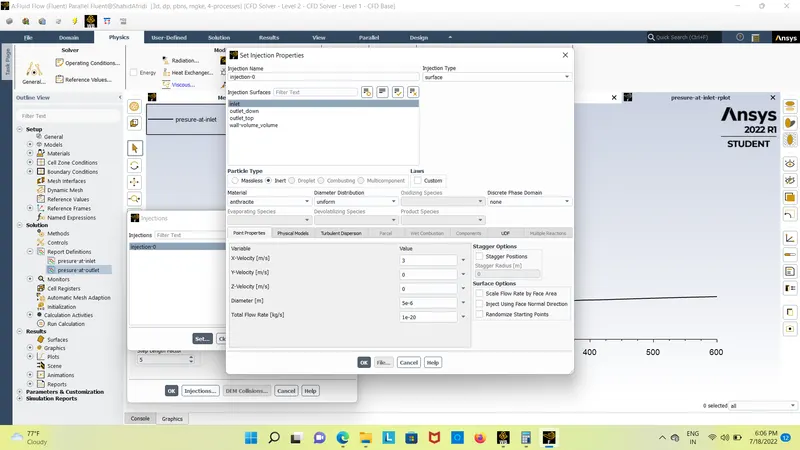
results:
case 1: when the particle size is 1 micrometers and velocity 3m/s
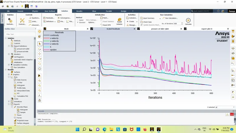
resduals plot:
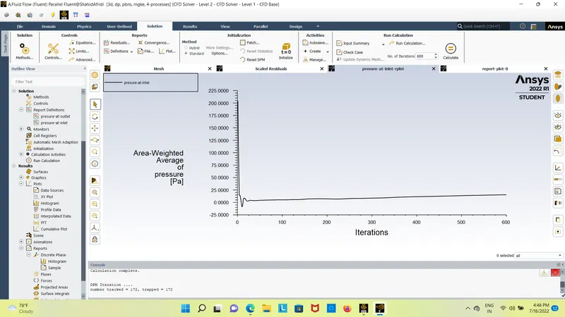
presure at inlet:
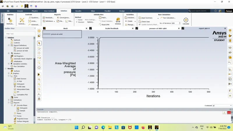
presure at outlet:
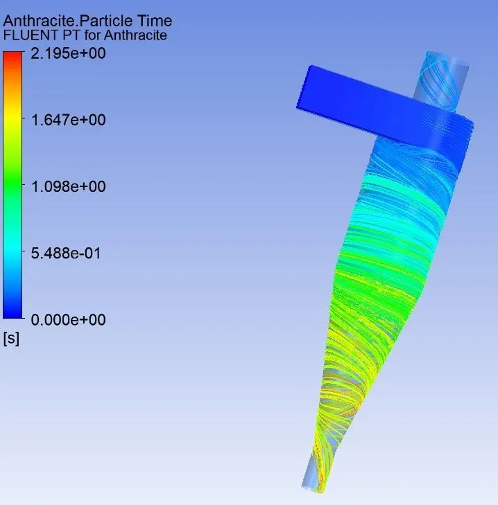
anthracite particle time:
presure-at-outlet
-------------------
Area-Weighted Average [Pa]
-------------------------------- -------------------
outlet_top -0.00010063624
presure-at-inlet
-------------------
Area-Weighted Average [Pa]
-------------------------------- -------------------
inlet 15.443819
total presure drop = presure at inlet - presure at outlet
total presure drop=15.443819-(-0.00010063624)
total presure drop=15.44390063 pa
`saparetion efficiency =number of particle traped/nomber of particle escaped`
`aparetion efficiency=172/172*100`
saparetiopn efficiency = 100%
case 2: when the particle size is 5 micrometers
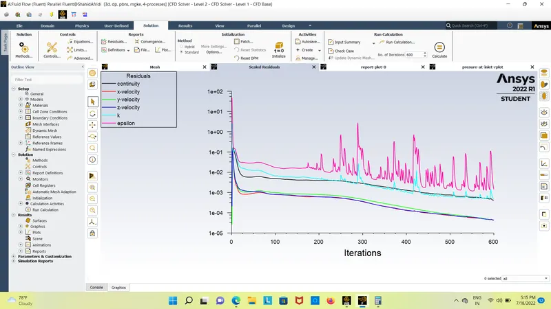
resduals plot:
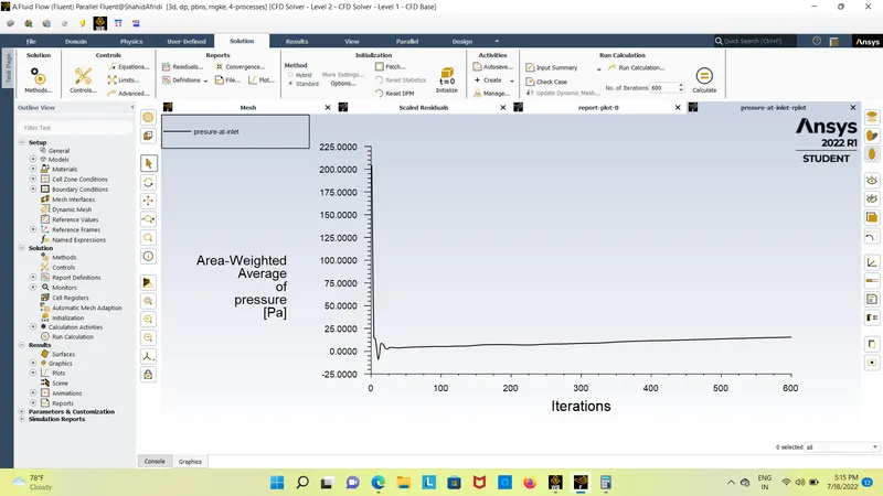
presure at inlet:
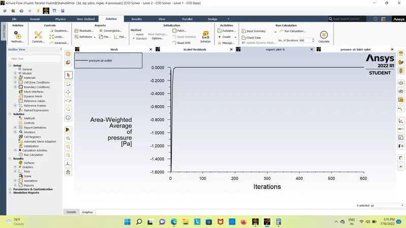
presure at outlet:
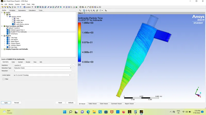
anthracite particle time:
presure-at-outlet
-------------------
Area-Weighted Average [Pa]
-------------------------------- -------------------
outlet_top -9.9545714e-05
presure-at-inlet
-------------------
Area-Weighted Average [Pa]
-------------------------------- -------------------
inlet 15.442388
total presure drop = presure at inlet - presure at outlet
total presure drop=15.443819-(-9.9545714e-05)
total presure drop=25.39847063 pa
`saparetion efficiency =number of particle traped/nomber of particle escaped`
`aparetion efficiency=168/172*100`
`strong>saparetiopn efficiency =97.67441`
2)To perform an analysis on a given cyclone separator model by varying the particle velocity from 1 m/sec to 5 m/sec and calculate the separation efficiency and pressure drop in each case. Discuss the results. [Use particle diameter size as 5 μm for all cases & keep flow velocity same as particle velocity]
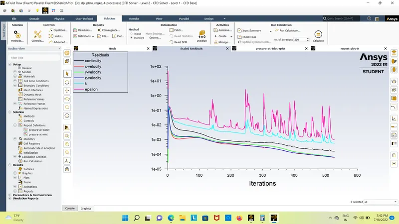
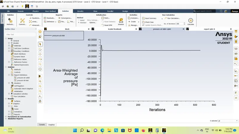
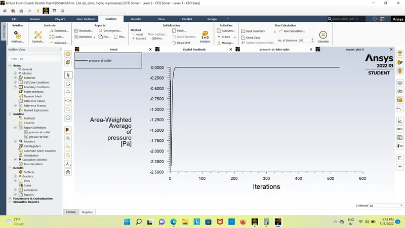
case 1: when velocity is equal to 1m/s and partical diameter 5 micrometer
Residuals:
presure at inlet:
presure at outlet:
anthracite particle time:
presure-at-outlet
-------------------
Area-Weighted Average [Pa]
-------------------------------- -------------------
outlet_top 0
presure-at-inlet
-------------------
Area-Weighted Average [Pa]
-------------------------------- -------------------
inlet 1.2999794
total presure drop = presure at inlet - presure at outlet
total presure drop=1.2999794-(0)
total presure drop=1.2999794 pa
`saparetion efficiency =number of particle traped/nomber of particle escaped`
`aparetion efficiency=161/172*100`
`strong>saparetiopn efficiency = 93.6046`
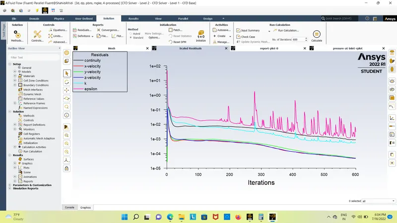
case 2: when velocity is equal to 5m/s and partical diameter 5 micrometer
residuals:
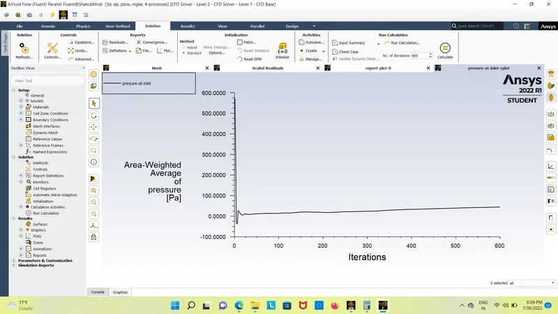
presure at inlet:
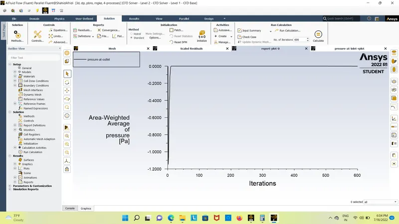
presure at outlet:
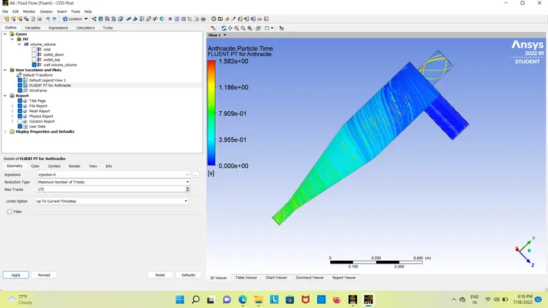
anthracite particle time:
presure-at-inlet
-------------------
Area-Weighted Average [Pa]
-------------------------------- -------------------
inlet 44.654838
presure-at-outlet
-------------------
Area-Weighted Average [Pa]
-------------------------------- -------------------
outlet_top -0.0010074516
total presure drop = presure at inlet - presure at outlet
total presure drop=44.654838-(-0.0010074516)
total presure drop=44.655807 pa
`saparetion efficiency =number of particle traped/nomber of particle escaped`
`aparetion efficiency=162/172*100`
`saparetiopn efficiency = 94.186046`
conclusion:
1. Simulation is completed for particle length varying from 1 m to 5 m with air and particle velocity as 3m/s. From the video, it is discovered that heavier particle is trapped at the lowest outlet and lighter particles are escaped at the outlet 1. however we can also see that lighter debris also get trapped at the bottom outlet because of interplay among lighter and heavier debris and there's an alternate of inertial forces among them as a result there is a switch of Kinetic power from heavier particle to the lighter particle, as a result, we can examine a sure quantity of heavier debris escapes thrugh the pinnacle outlet.the collection efficiency of cyclones varies as a function of particle length, density, and cyclone layout.
2. Cyclone performance will generally increase with the growth in particle size, density, inlet duct speed, cyclone frame length, quantity of gas revolutions in the cyclone, the ratio of cyclone body diameter to fuel go out diameter, inlet dirt loading, smoothness of the cyclone internal wall.
3. The efficiency of the cyclone will lower with an growth inside the parameters inclusive of gas viscosity, cyclone body diameter, gasoline go out diameter, gasoline inlet duct area, gas density, leakage of air into dust outlet. With the boom in inlet velocity or particle length the performance increases..
four. pressure drop happens due to the subsequent additives:
Loss due to the growth of gas inside the cyclone chamber.
Loss because of rotational kinetic energy.
Loss due to wall frictional forces.