Week 8 - Simulating Cyclone separator with Discrete Phase Modelling
AIM:
To perform analysisi on cyclone separator and calculate the separation efficiency and pressure drop.
OBJECTIVE:-
- To write a few words about any four empirical models used to calculate the cyclone separator efficiency.
- To perform an analysis on a given cyclone separator model by varying the particle diameter from 1 μm to 5 μm and calculate the separation efficiency in each case. Discuss the results. [Use both the velocity's as 3m/sec.]
- To perform an analysis on a given cyclone separator model by varying the particle velocity from 1 m/sec to 5 m/sec and calculate the separation efficiency and pressure drop in each case. Discuss the results. [Use particle diameter size as 5 μm for all cases & keep flow velocity same as particle velocity]
DESCRIPTION:
Cyclone separators are devices that are used to remove particulate matter larger than 10`mum` in diameter. But there exists some high efficiency cyclone separators which remove particles of size 2.5 `mum`. Although these devices are inexpensive they are however not very effective when larger particulate matter around say 200`mum` diameter comes into play. In such cases, gravity settling chamber or momentum separator are better options.
To carry the simulation of cyclone chamber we go for DPM(discrete phase modelling) methodology. DPM is emplyed when you want to represent the solid particles in gas/liquid or say liquid droplets in gas or bubbles in liquid. So, in DPM two phases are considered. One is called the continuous phase and the other is called the discrete phase.
So the continuous phase consists of the fluid i.e flowing with in the fluid volume and the discrete phase will consists of the smaller particles that are supposed to be interacting with the continuous phase. The discrete phase can also exchange momentum, mass and energy with the fluid phase/continuous phase in this case.
EMPIRICAL MODELS USED FOR CYCLONE SEPARATOR EFFICIENCY:
1.IOZIA AND LEITH MODEL:
Iozia and Leith logistic model is a modified version of Barth model which is developed based on force balance.The model assumes that a particle carried by the vortex endures the influence of two forces , a centrifugal force Z and flow resistance W, core length Zc and dore diameter dc are given as
`zc=(H-S)-H-S(D/B)-1[((dc)/B)-1]` for dc>B
`zc=H-S` for dc<B
`dc=0.47((ab)/D^2)^(-0.25).((De)/D^(1.4))`
The addition made by Iozia and leith on the original barth model is the core length zc and slope paramter `beta` expression which is derived based on the statistical analysis of experimental data of cyclone with D=0.25m. The collection efficiency `etai` of particle diameter dpi can be calculated from
`etai=1/(1+((dpc)/(dpi))^beta)etai = 11+(dpcd-pi)beta^n>dpc = [(9muQ)/(piPpZcV^2max]^(0.5)]`
where `dpc^n=dpcc = c0` at `theta=0` is the 50%cut given by barth.
2.LI AND WANG MODEL:
The Li and Wang model include particle bounce or re-entrainment and turbulent diffusion at the cyclone wall.A two dimensional analystical expression of particle distribution in the cyclone is obtained. Li and wang model was developed based on the following assumptions
1.The radial particle velocity and the radial concentration profile are not constant for uncollected particles within the cyclones.
2.Boundary conditions with the consideration of turbulent diffusion coefficient and particle bounce re-entrainment on the cyclone wall are
`c=c0^n>r = D/2`
`Dr(delc)/(delr) = (1-alpha)wc` at the tangential velocity is related to the radius of cyclone by
`uR^n` = constant
The concentration distribution in a cyclone is given as
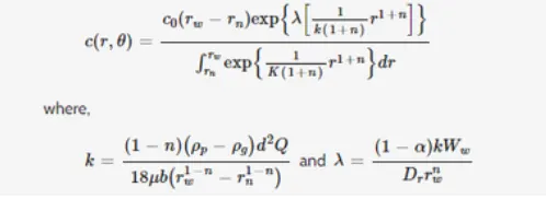
The resultant expression of the collection efficiency for a `theta1=2pi(S+L)/a` particle of size is given as `ni=1-exp{-lamdatheta1}`
where `theta1=2pi(S+L)/a`
3.KOCH AND LICHT MODEL
Koch and light model collection theory inherently turbulent nature of cyclones and the distribution of gas residence times within the cyclone koch and Licht.
The particle motion in the entry and collection regions with in the additional following assumptions
1.The tangential velocity of a particle is equal to the tangential velocity of the gas flow, i.e there is no slip in the tangential direction between the particle and the gas.
2.The tangential velocity is related to the radius of cyclone by `uR^n` = constant.
A force balance and an equation on the particle collection yields the grade efficiency `etai`
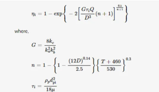
`etai=rhopdpi218mu^n>Nc = 1/a(h+(H-h)/2)`
G is the factor related to the configuration of the cyclone, n is related to the vortex and `gamma` is the relaxation term.
4.LAPPLE MODEL
Lapple model was developed based on the force balance without considering the flow resistance.Lapple assumed that a particle entering the cyclone is evenly distributed across the inlet opening.The particle that travels from inlet half-width to the wall in the cyclone is collected with 50% efficiency.The semi-empirical relationship developed by Lapple to calculate a 50% cut diamter dpc is
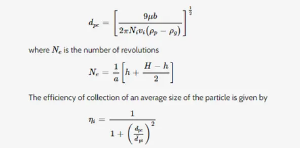
The separation efficiency based on this model is calculayed at the result section and compared with the experimental data for 5`mum` at `3m/s`
PROCEDURE AND SIMULATION STEPS FOR THE MODEL:
Opening the model file in space claim
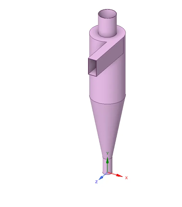
Now as we need to carry the analysis on fluid volume we are extracting the volume for the model from prepare>volume extract and selecting the edges (inlet edge, upper outlet for lighter air, bottom outlet for heavier particles).
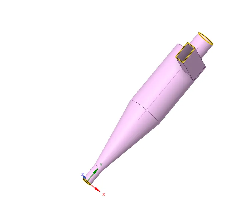
So now we got the volume
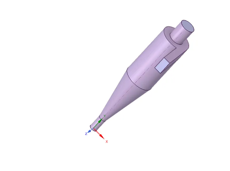
Then suppressing physics for cyclone separator so the geometry of model doesn't interrupt and we are only left with the volume
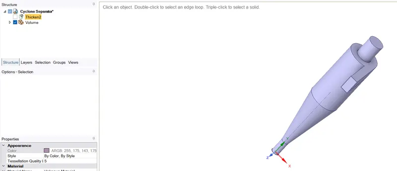
Now closing the space claim and going for meshing
Inserting the method and secting the body and using cartisian method for meshing body
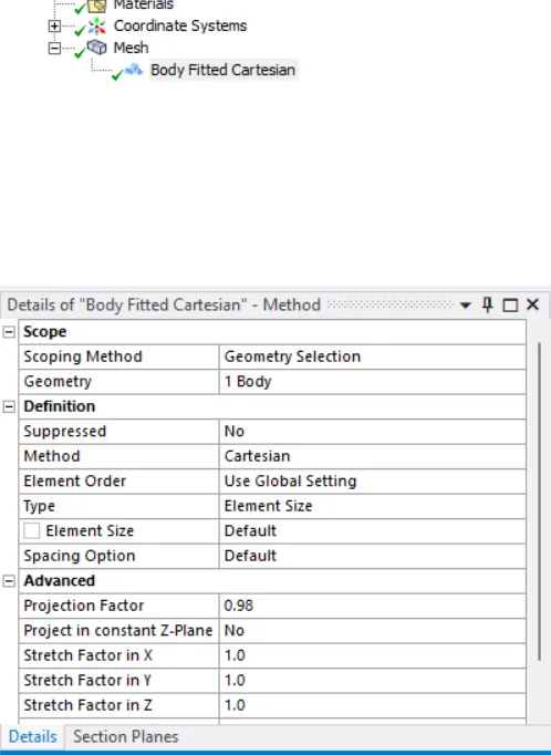
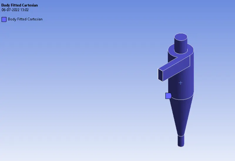
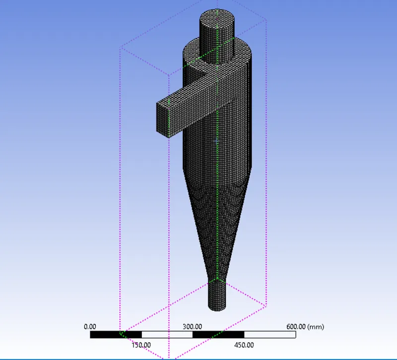
Using the element size for mesh as 10mm we generate the mesh and its as follows
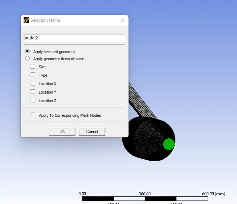
Next is naming the parts
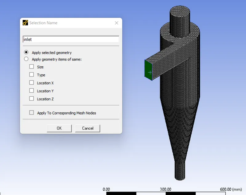
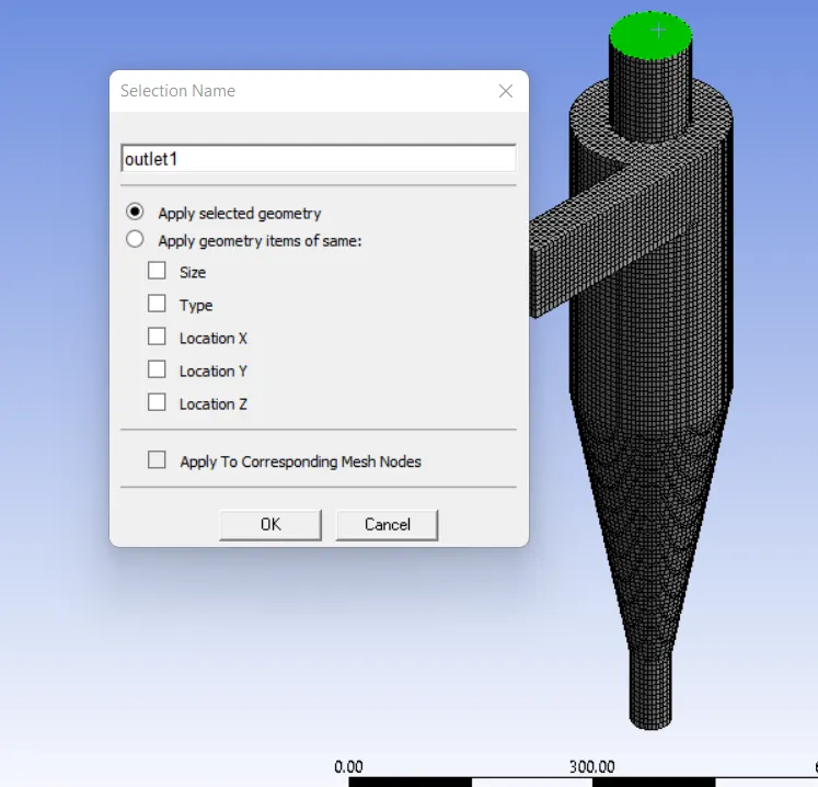
Now opening up the Ansys fluent
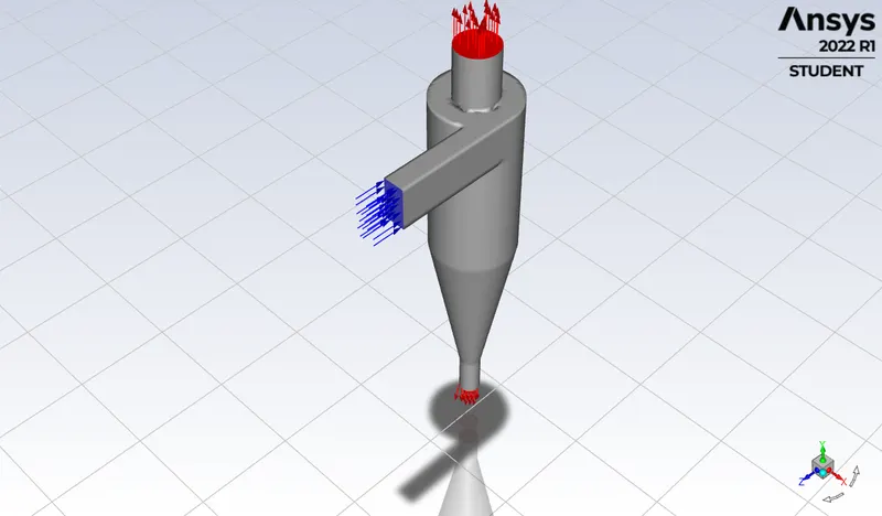
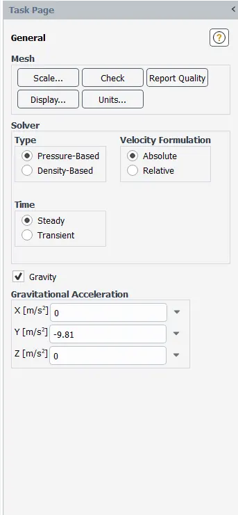
Using the pressure based steady state solver with gravity acting in -Y direction
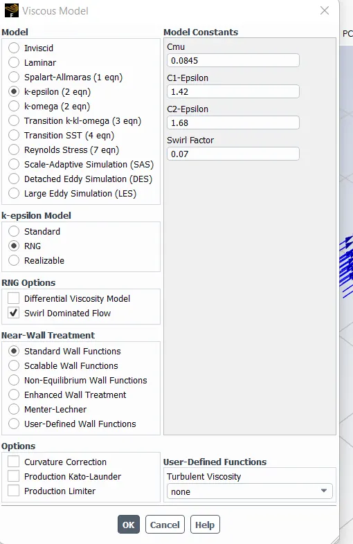
Next we use the viscous model with k-epsilon RNG method which is the improved method of standard model which enhances the accuracy of swirling flows.
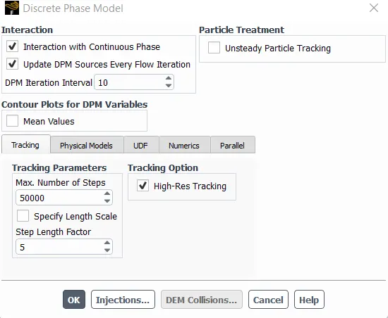
Next truning on the discrete phase creation.There are two ways of carrying the discrete phase modelling, one is the uncoupled flow and another is the coupled flow.In the uncoupled flow the discrete phase will not have any interaction with the continuous phase while the coupled flow the discrete phase will influence the flow of the continuous phase.But since the size of the particles injected into the cyclone separator is very small usage of both the types of flow shouldn't matter much.
Enabling interact with continuous phases to enable coupled flow
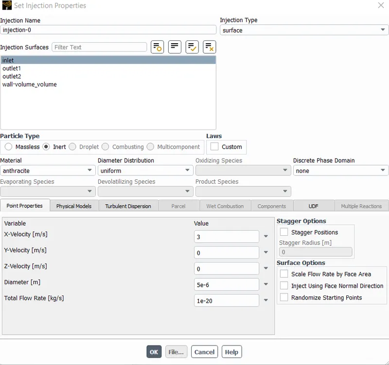
Now for injection of particles
For inlet with 3m/s in x-direction and diameter 5 micro meter
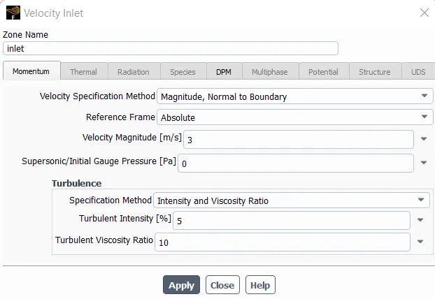
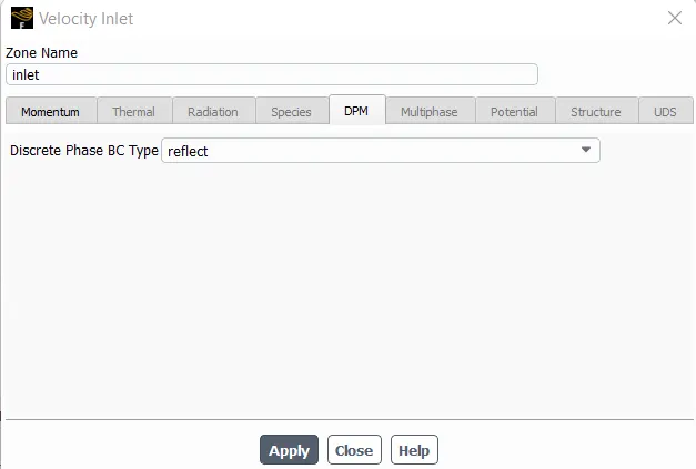
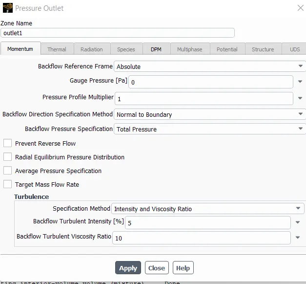
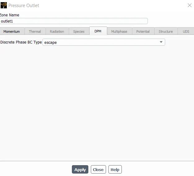
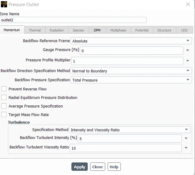
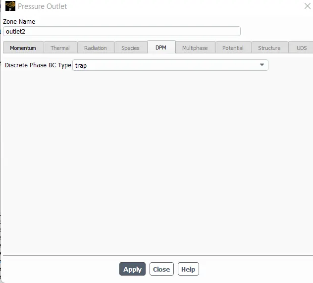
Now specifying the boundary conditions
For inlet
for outlet 1
For outlet2
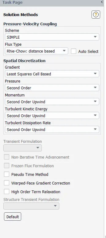
Then for solution methods we go for SIMPLE with second order upwind for Turbulent kinetic energy and turbulent dissipation rate
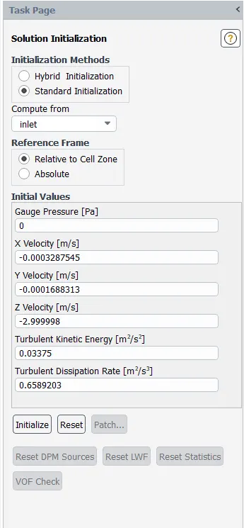
For initialization methods we choose the following
Then running the simulation for 600iterations
After completion of the calculation, we need to export the particle tracking data.
File>export>particle historical data
PART1
SIMULATION WITH 1MICRO-METER WITH 3m/s PARTICLE & FLOW VELOCITY
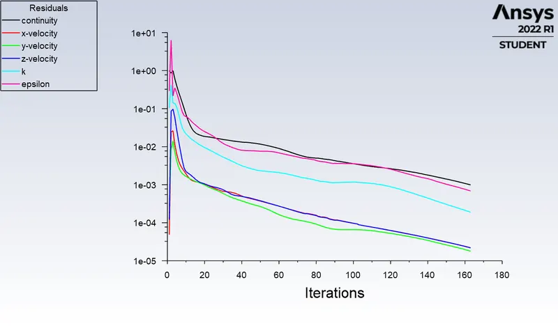
The residuals are
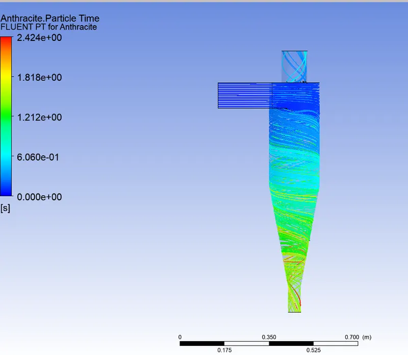
The anthracite particle time
DPM Iteration ....
number tracked = 91, escaped = 22, trapped = 69
Mass Flow on inlet
0.018358 [kg s^-1]
Mass Flow on outlet1
1.66627e+18 [kg s^-1]
Mass Flow on outlet2
-1.58416e+18 [kg s^-1]
SIMULATION WITH 2MICRO-METER WITH 3m/s PARTICLE & FLOW VELOCITY
The residuals are
The anthracite particle time
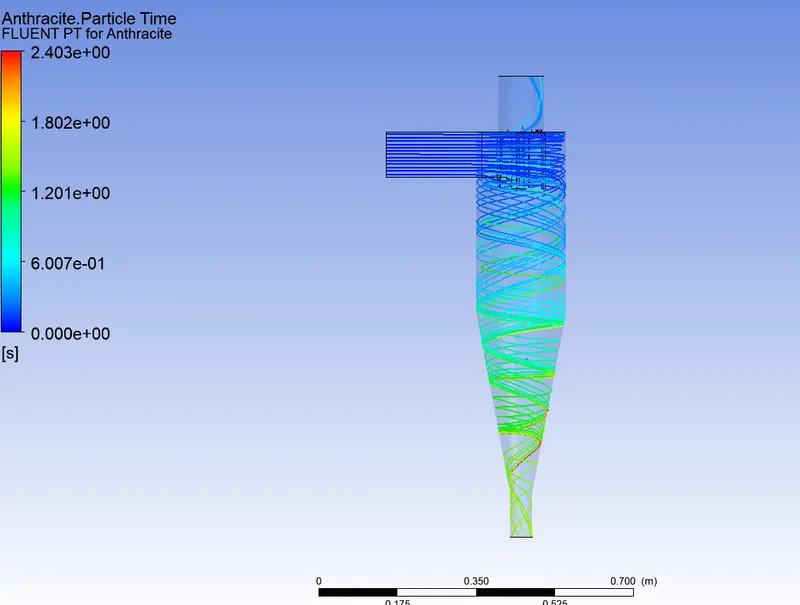
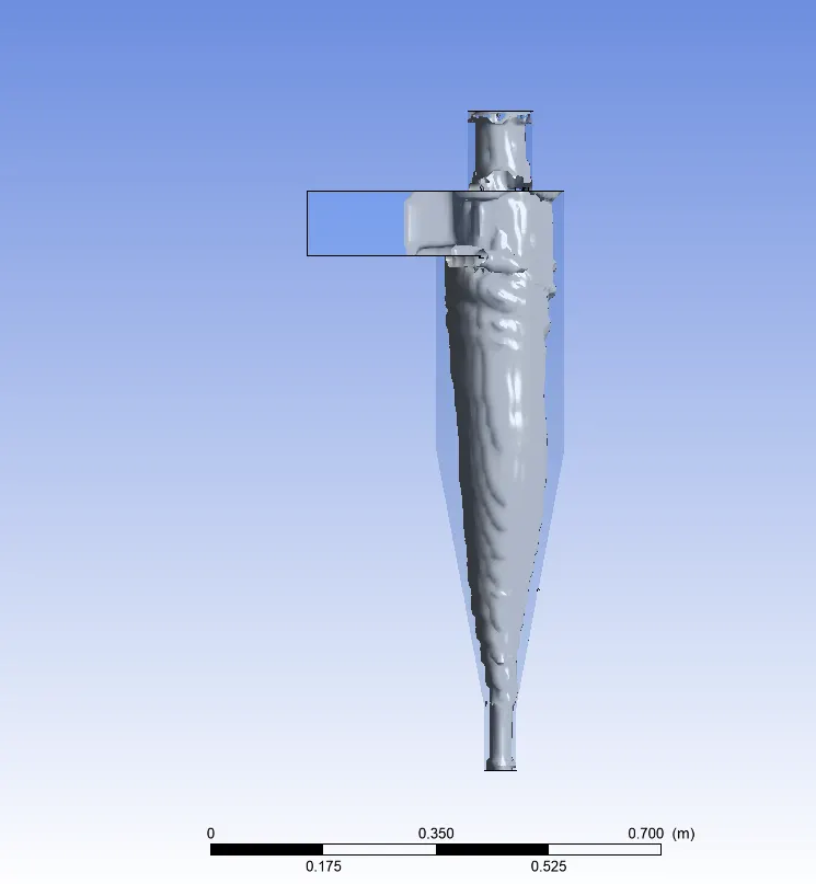
number tracked = 91, escaped = 22, trapped = 69
SIMULATION WITH 3MICRO-METER WITH 3m/s PARTICLE & FLOW VELOCITY
The residuals
The Anthracite particle time
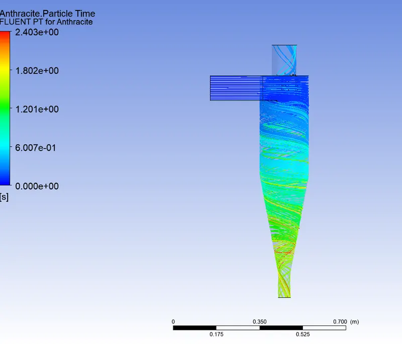
DPM Iteration ....
number tracked = 91, escaped = 21, trapped = 70
SIMULATION WITH 4MICRO-METER WITH 3m/s PARTICLE & FLOW VELOCITY
The residuals
The anthracite particle time
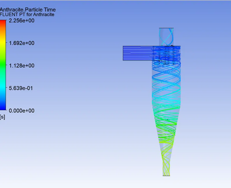
DPM Iteration ....
number tracked = 91, escaped = 31, trapped = 60
SIMULATION WITH 5MICRO-METER WITH 3m/s PARTICLE & FLOW VELOCITY
The residuals
The anthracite particle time
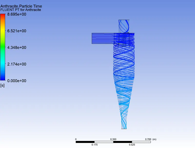
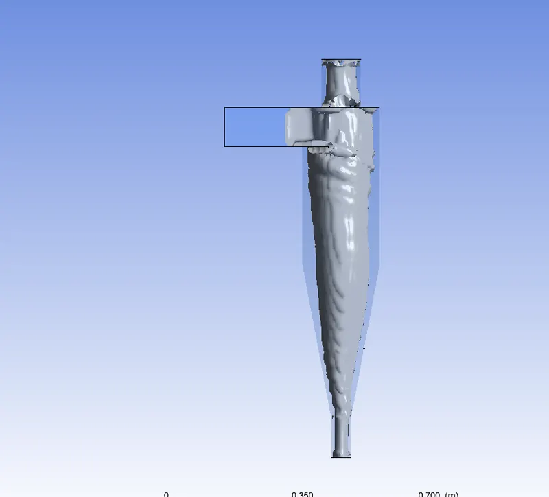
DPM Iteration ....
number tracked = 91, escaped = 38, trapped = 52, incomplete = 1
PART2
SIMULATION WITH 5MICRO-METER WITH 1m/s PARTICLE & FLOW VELOCITY

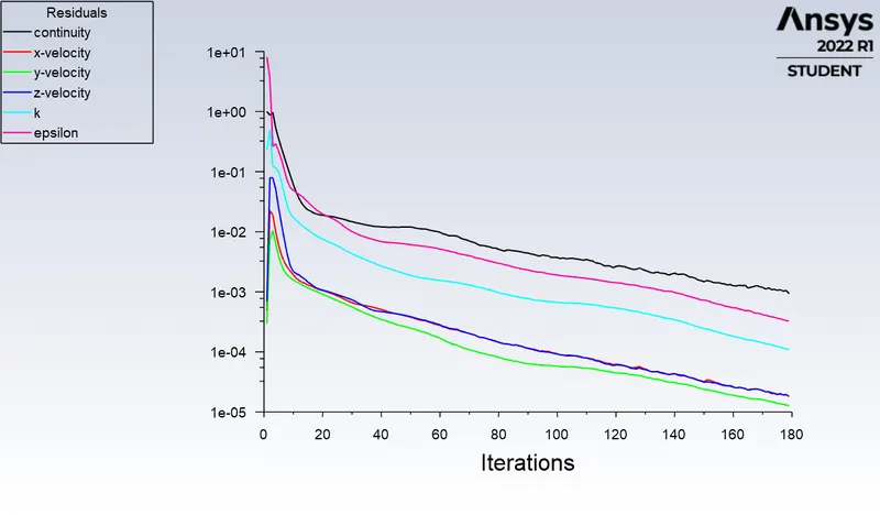
inlet 1.6163799
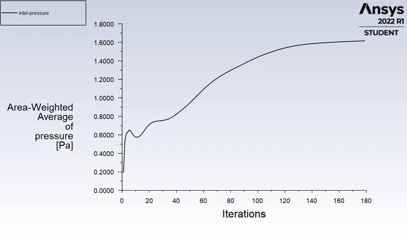
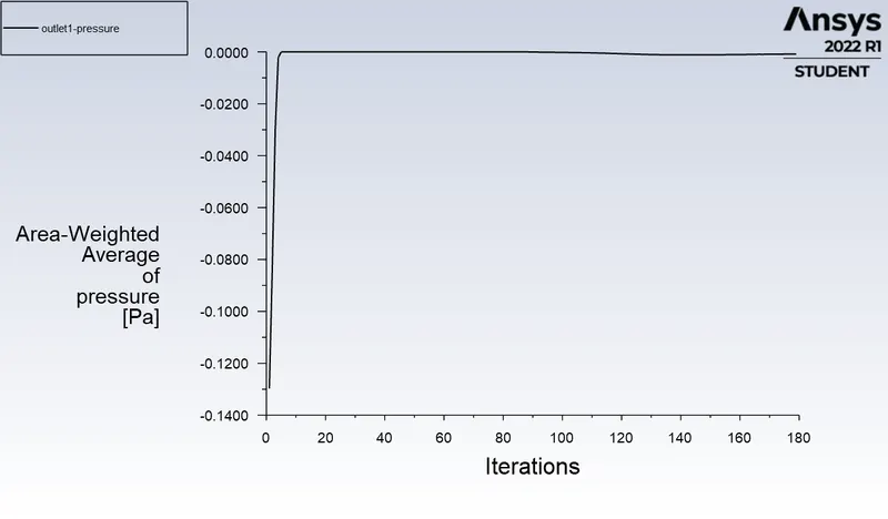
outlet1 -0.0008422388
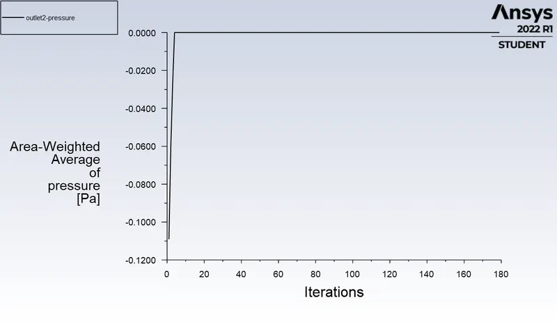
outlet2 0
number tracked = 91, escaped = 14, trapped = 77
SIMULATION WITH 5MICRO-METER WITH 2m/s PARTICLE & FLOW VELOCITY
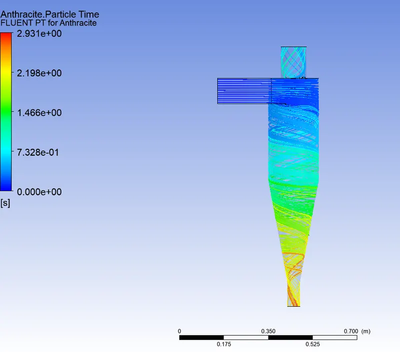
The anthracite particle time
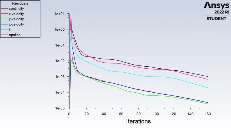
The residuals
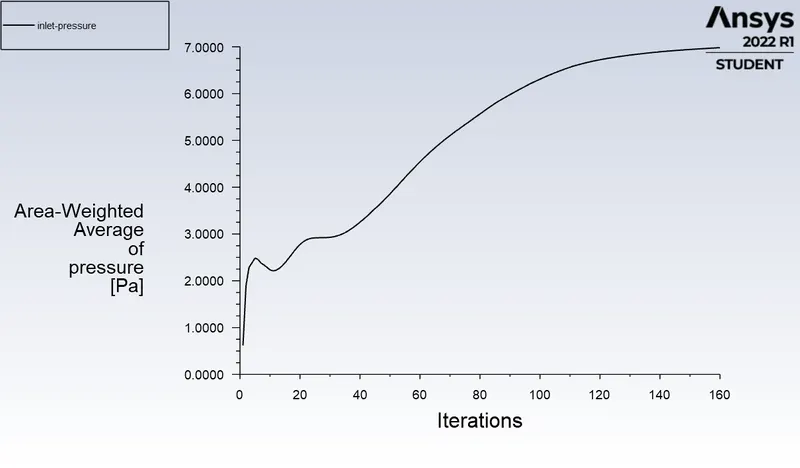
The input pressure plot
inlet 6.9810609
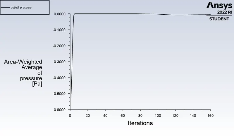
The output pressure plot
outlet1 -0.0058632293
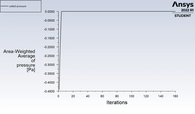
The output pressure plot
outlet2 0
number tracked = 91, escaped = 30, trapped = 61
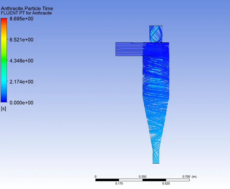
SIMULATION WITH 5MICRO-METER WITH 3m/s PARTICLE & FLOW VELOCITY
The Anthracite particle time
The residuals
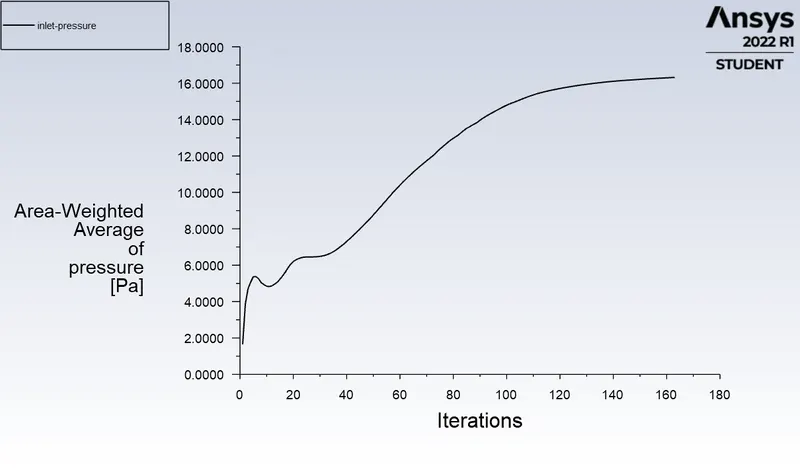
The inlet pressure
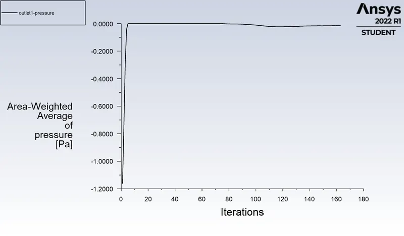
The output presssure
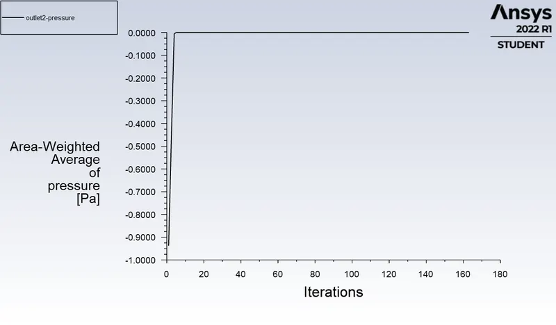
The output pressure
inlet pressure 16.316174 Pa
outlet1 pressure -0.014792986 Pa
outlet2 pressure 0 Pa
number tracked = 91, escaped = 38, trapped = 53
SIMULATION WITH 5MICRO-METER WITH 4m/s PARTICLE & FLOW VELOCITY
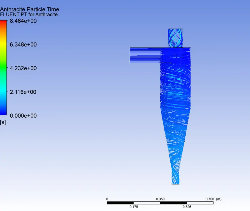
The Anthracite particle time
The residuals are
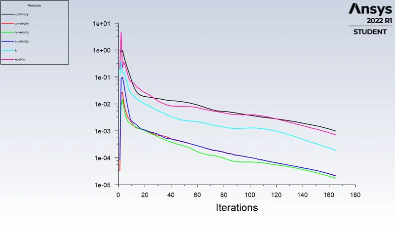
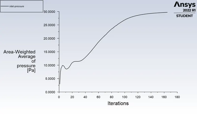
The inlet pressure plot
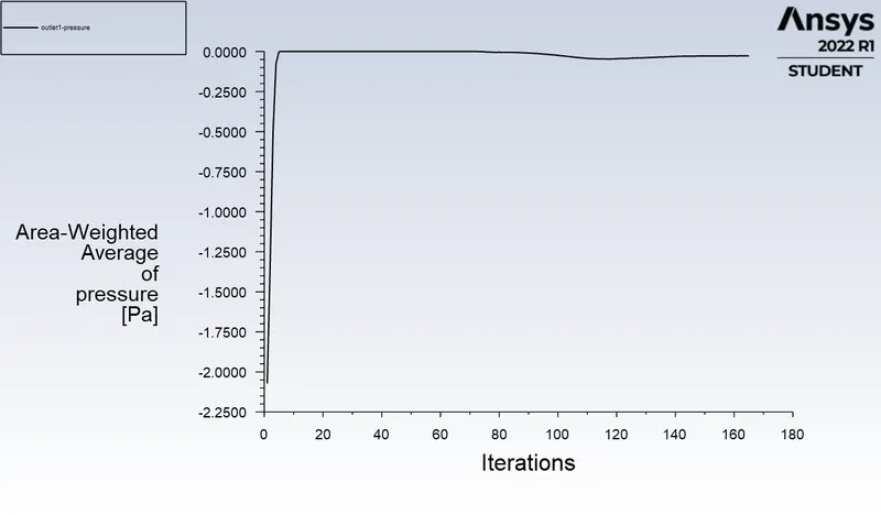
The outlet pressure plot
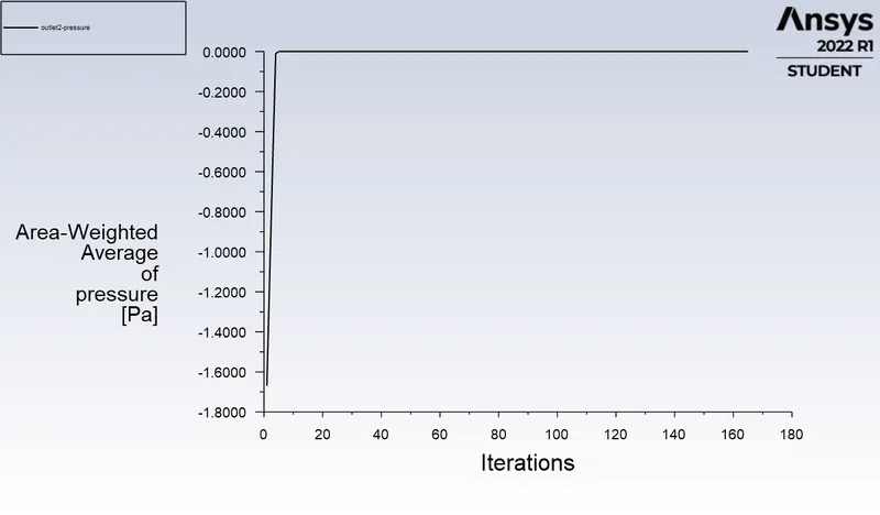
The outlet pressure plot
number tracked = 91, escaped = 36, trapped = 52, incomplete = 3
inlet pressure 29.700209 Pa
outlet1 pressure -0.027041053 Pa
outlet2 pressure 0 Pa
SIMULATION WITH 5MICRO-METER WITH 5m/s PARTICLE & FLOW VELOCITY
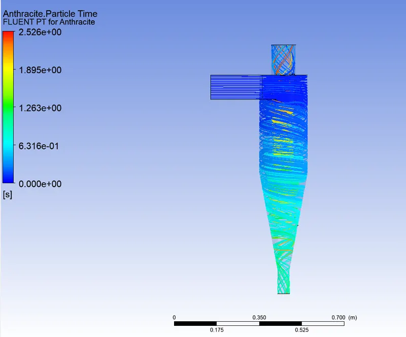
The Antracite particle time
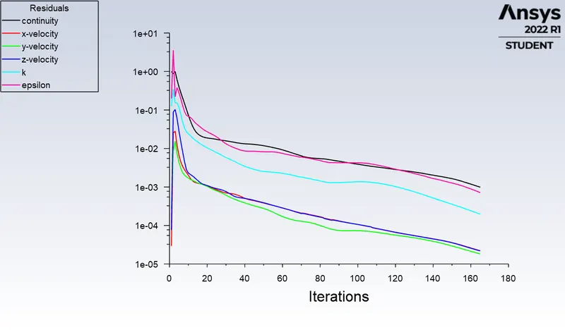
The residuals
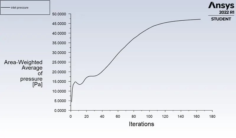
The inlet pressure plot
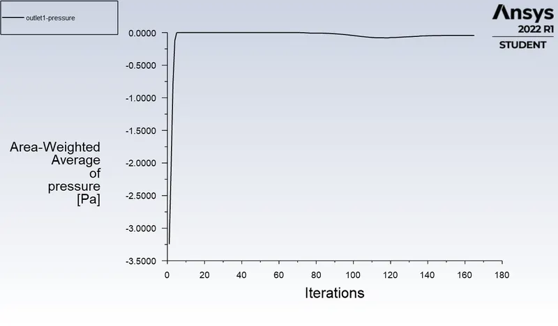
The outlet pressure plot
The outlet pressure plot
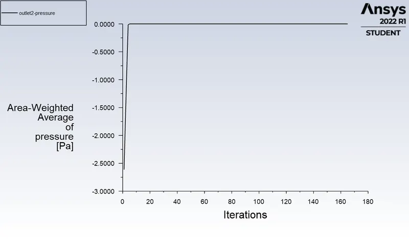
number tracked = 91, escaped = 39, trapped = 52
inlet pressure 47.160658 Pa
outlet1 pressure -0.043638045 Pa
outlet2 pressure 0 Pa
SEPARATION EFFICIENCY
It is defined as the ration of particles of given size collected in the cyclone compared to those of that size going into the cyclone.
Observation shows that the separation efficiency increases with increasing particle mean diameter and density.Increasing gas tangential velocity, decreasing cyclone diameter, increasing cyclone length, extraction of gas along with solids through the cyclone legs.
Therefore, separation efficiency `etai`= No of particles trapped/No of particles tracked
PRESSURE DROP:
Pressure drop across the cyclone is of much importance in a cyclone separator.The pressure drop significantly affects the performance parameter of a cyclone.The total pressure drop in a cyclone will be due to entry and exit losse and kinetic friction and kinetic energy losses in the cyclone.Normally the most significant pressure drop occurs in the body due to swirl and energy dissipation.
Pressure drop is defined as the difference in total pressure between two points of a fluid carrying the volume.
Pressure drop `DeltaP`=Total inlet pressure-Total outlet pressure
RESULTS:
PART1: For varying diameter with constant speed of 3m/s
| CASES | PARTICLE SIZE | PARTICLE TRACKED (m) | PARTICLE ESCAPED | PARTICLE TRAPPED | PARTICLES INCOMPLETE | SEPARATION EFFICIENCY % |
| case1 | 1e-6 |
91 |
22 | 69 | 0 | 75.82% |
| case2 | 2e-6 | 91 | 22 | 69 | 0 | 75.82% |
| case3 | 3e-6 | 91 | 21 | 70 | 0 | 76.92% |
| case4 | 4e-6 | 91 | 31 | 60 | 0 | 65.93% |
| case5 | 5e-6 | 91 | 38 | 52 | 0 | 57.14% |
PART2: For varying velocities with 5e-6 m diameter of particle
| CASES | VELOCITIES (m/s) | PARTICLE SIZE (m) | PARTICLE TRACKED | PARTICLE ESCAPED | PARTICLE TRAPPED | PRESSURE DROP | SEPARATION EFFICIENCY % |
| case1 | 1 | 5e-6 | 91 | 14 | 77 | 1.615 | 84.61% |
| case2 | 2 | 5e-6 | 91 | 30 | 61 | 6.975 | 67.03% |
| case3 | 3 | 5e-6 | 91 | 38 | 53 | 16.298 | 58.24% |
| case4 | 4 | 5e-6 | 91 | 36 | 52 |
29.673 |
57.14% |
| case5 | 5 | 5e-6 | 91 | 39 | 52 |
47.117 |
57.14% |
CONCLUSION:
Both the parts are simulated and we observe that separation efficiency depends on diameter as well as velocity of the particles.As increased diameter and velocity gives decreased separation efficiency.
Velocity has a greater impact as compared to the diameter of the particles.
Pressure drop is dependent on velocity.For constant velocity with varying diameter sizes the pressure drop remains almost constant.
Increased velocity causes increase in pressure drop.