Week 8 - Simulating Cyclone separator with Discrete Phase Modelling
OBJECTIVE: To simulate cyclone separator using discrete phase modelling.
THEORY: Cyclone Separators or simply cyclone are separation devices that use the principal of inertia to remove particulate matter from fluids. Cyclone separator is one many air pollution removers known as pre-cleaners since they generally remove larger pieces of particulate matter.
This prevents finer filtration methods from having to deal with large more abrasive particles later on. In addition, several cyclone separators can operate in parallel and the system is called multicyclone.
Cyclone separator works much like a centrifuge but with a continuous feed of dirty air. In a cyclone separator dirty fluid is fed into a chamber. The insides of the chamber create a spiral vortex, similar to a tornado. The lighter particles of this fluid have less inertia so it is easier for them to be influenced by the vortex and travel up it, the larger particle posses more inertia and are not easily influenced by the vortex.
Since these larger particles have difficulty following the high-speed spiral motion of the gas and the vortex the particles hit the inside wall of the container and drop down into the collection hopper. These chambers are shaped like an upside-down cone to promote the collection of these particles at the bottom of the container. The cleaned fluid escapes out of the chamber.
There are 4 empirical model used to calculate the separation efficiency of the cyclone separator are;
IOZIA AND LEITH MODEL: It is a modified version of Barth (1956) model which is developed based on the force balance. The model assumes that a particle carried by the vortex endures the influence of two forces a centrifugal force Z and a flow resistance.
LI AND WANG MODEL: This model includes particle bounce or reattainment and turbulent diffusion at the cyclone wall. A two-dimensional analytical expression of particle distribution in the cyclone is obtained. The model is based on the following assumptions “the radial particle velocity and the radial concentration profiles are not constant for uncollected particles within the cyclone.
KOCH AND LICHT MODEL: This model recognised the inherently turbulent nature of cyclones and the distribution of gas residence times within the cyclone. The following assumptions were made tangential velocity of a particle is equal to the tangential velocity of the fluid flow i.e., there is no slip in between particle and gas in the tangential direction. Tangential velocity is related to the radius of the cyclone.
LAPPLE MODEL: It was developed on force balance without considering the flow resistance. Lapple assumed that a particle entering cyclone is evenly distributed across the inlet opening. The particle that travels from inlet half width to the wall in the cyclone is collected with 50% efficiency.
In overall the collection efficiency of the cyclone varies as a function of density, particle size, and cyclone design. Cyclone efficiency would mainly increase with increase in size of the particle or density. Similarly, cyclone efficiency will decrease with the increase in parameters such as fluid viscosity, cyclone body diameter fluid density leakage of air into dust outlet.
PROCEDURE: We start by preparing geometry by space-claim then use Ansys mesher for meshing and setup the problem using Ansys fluent and results using CFD-post.
GEOMETRY
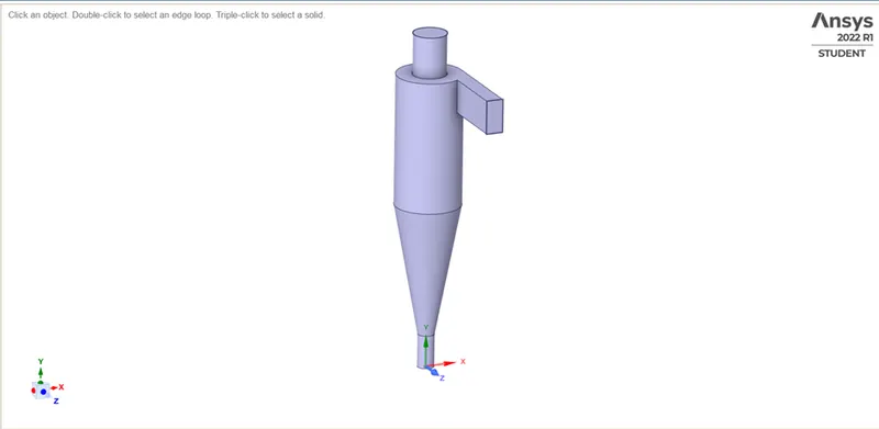
We start by opening the model file in space-claim and after that we use the volume extract tool by using the edge selection method to extract the fluid flow volume in the cyclone separator, once the cyclone volume is extracted, we hide the other parts in the model and supress them for physics and close space-claim.
MESHING
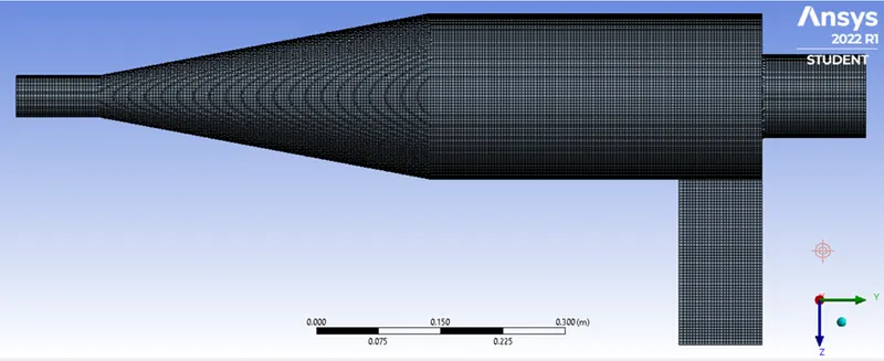
For meshing we open up the geometry in the Ansys mesher and then generate the base mesh on which we insert the method and use the Cartesian method and keep the element size as 9mm and after that we name the inlet and the two outlets using the face selection tool. Once meshing is done, we close the mesh GUI and update the meshing the workbench.
FLUENT SETUP
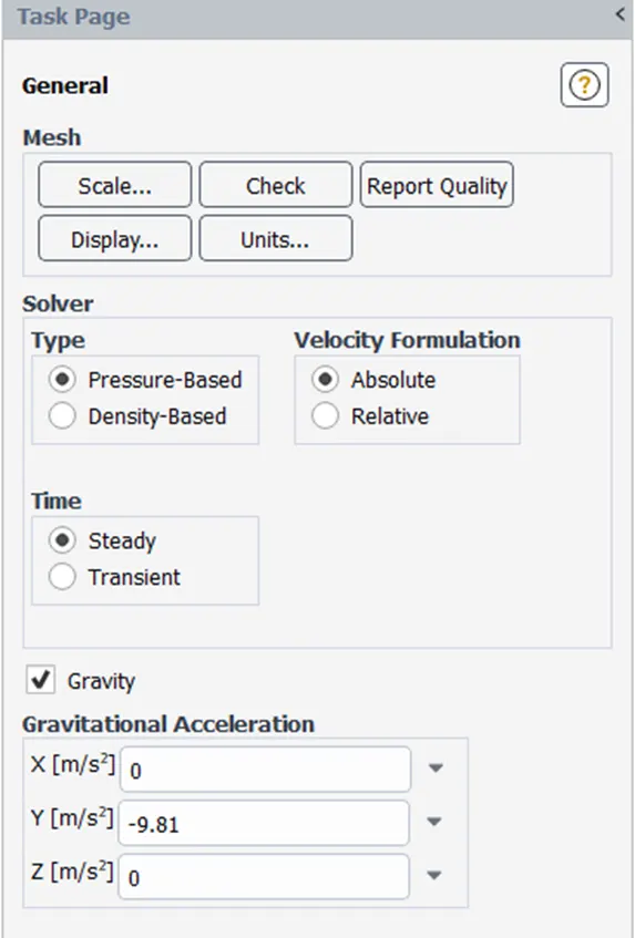
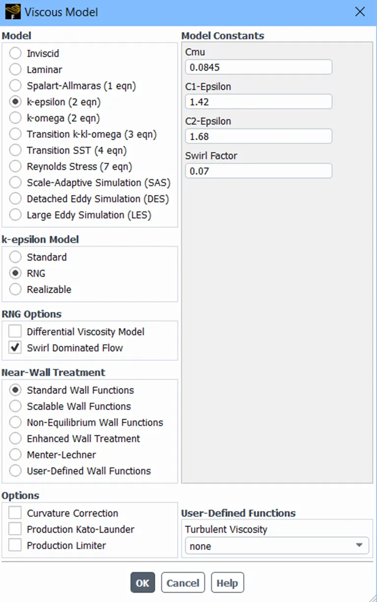
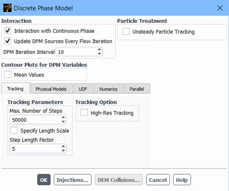
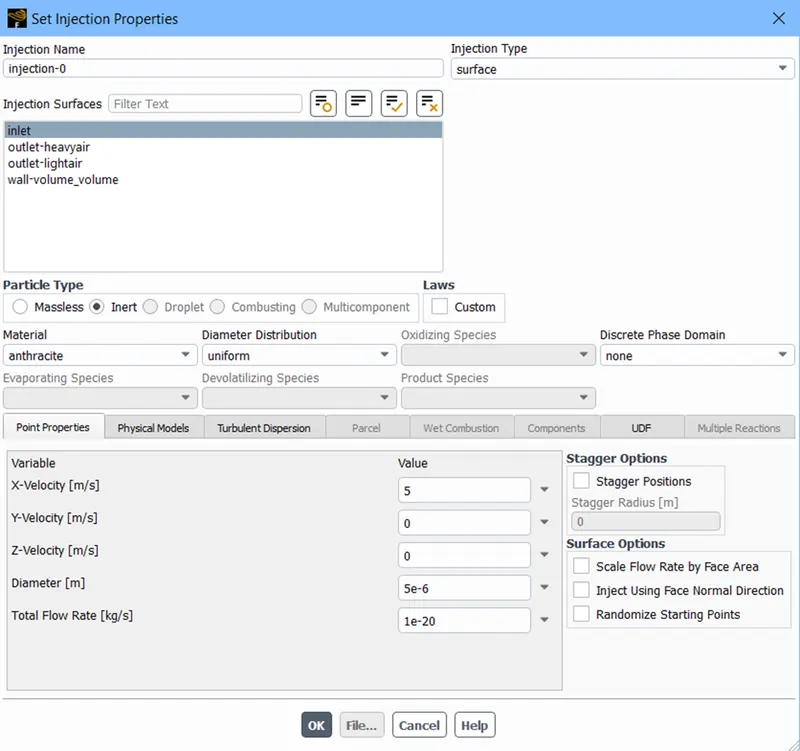
After completing the meshing part, we open fluent to setup the simulation as well as solve it, and we do so by first setting the simulation as steady state analysis and we enable the gravity also. After that we use the K-epsilon RNG Swirl dominant viscous mode. Once done we head to discrete phase model where interaction with continuous phase is enabled to have coupled flow, DPM iteration interval is set to be 10 and maximum tracking step number is set to be 50000 then we head to injection in DPM and set the Particle type as inert and the material is set as anthracite injection type is set to be surface and select inlet for it. And select other values depending upon the test cases. After it is done, we set the boundary condition as mentioned in the task. And in discrete phase model make sure high precision tracking is turned off for accurate results.
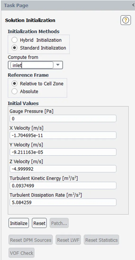
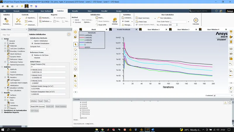
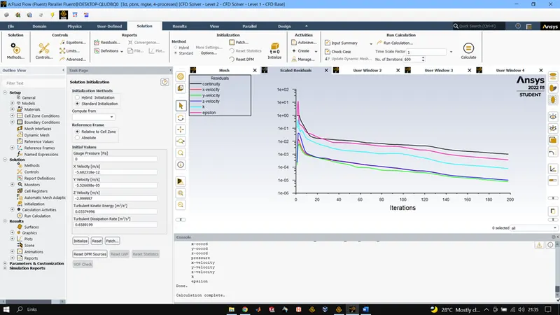
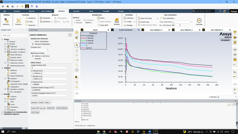
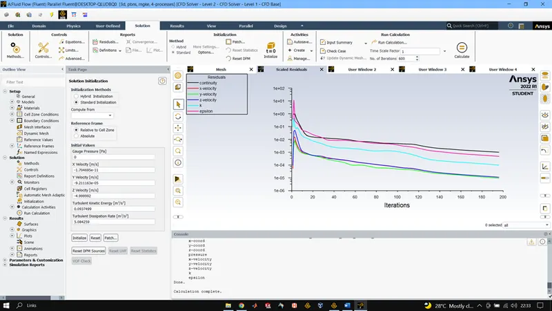
After completing all these steps use the standard method of initialisation and initialise each test case to compute from inlet, once done run the simulation for 600 iterations.
Once we have the results use the export option to export particle data and save it in a folder.
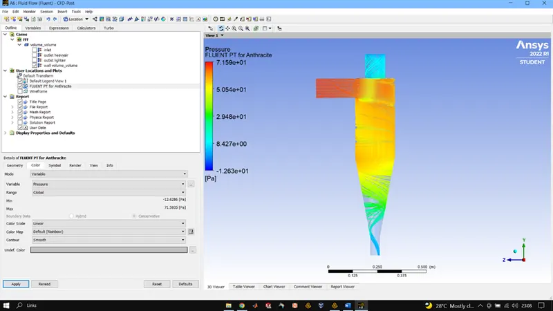
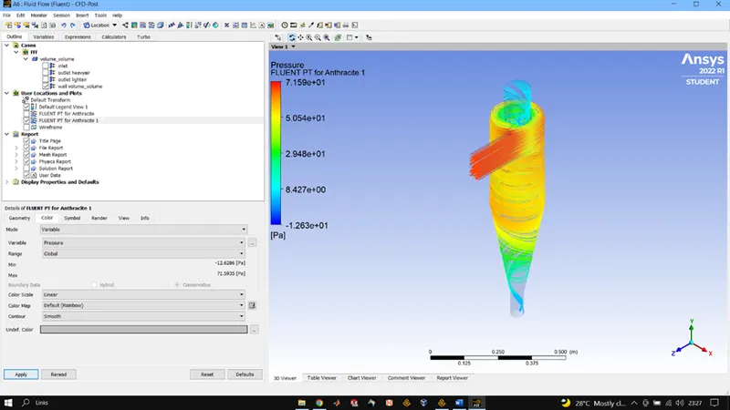
In the post processor use import option to import the saved particle data, decrease the transparency of the fluid flow volume and use anthracite particle time to see the residence time of each particle.
And use the calculator to calculate various values.
RESULTS:
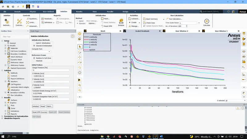
4mu3m/s
DPM Iteration ....
number tracked = 378, escaped = 113, trapped = 150, incomplete = 115
Separation efficiency = 47.08%
5mu3m/s
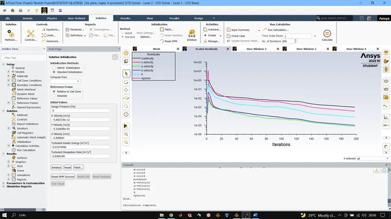
DPM Iteration ....
number tracked = 378, escaped = 98, trapped = 178, incomplete = 102
Separation efficiency = 39.68%
Pressure drop = 27.46
3mu3m/s
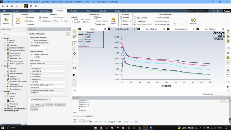
DPM Iteration ....
number tracked = 378, escaped = 127, trapped = 137, incomplete = 114
Separation efficiency = 36.24%
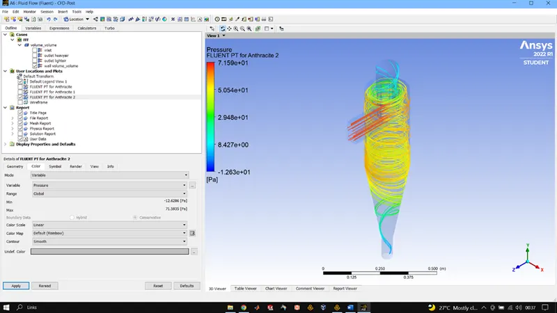
2mu3m/s
DPM Iteration ....
number tracked = 378, escaped = 146, trapped = 136, incomplete = 96
Separation efficiency = 35.97%
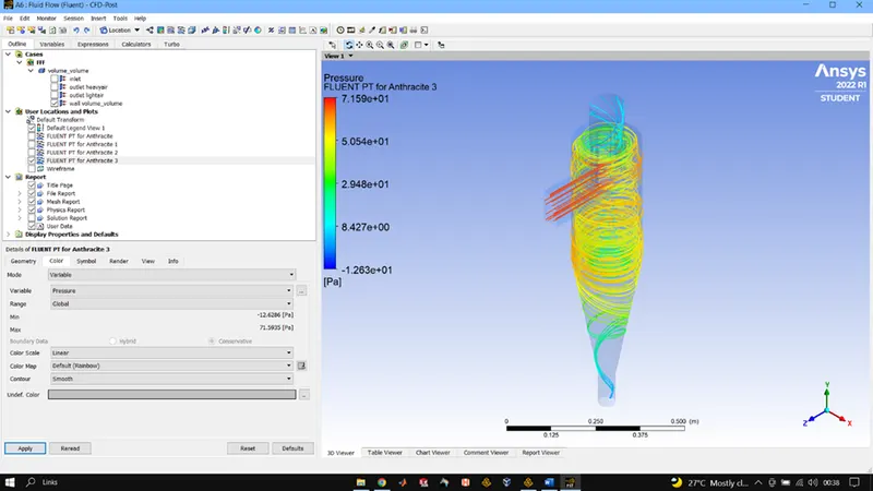
1mu3m/s
DPM Iteration ....
number tracked = 378, escaped = 170, trapped = 113, incomplete = 95
Separation efficiency = 29.89%
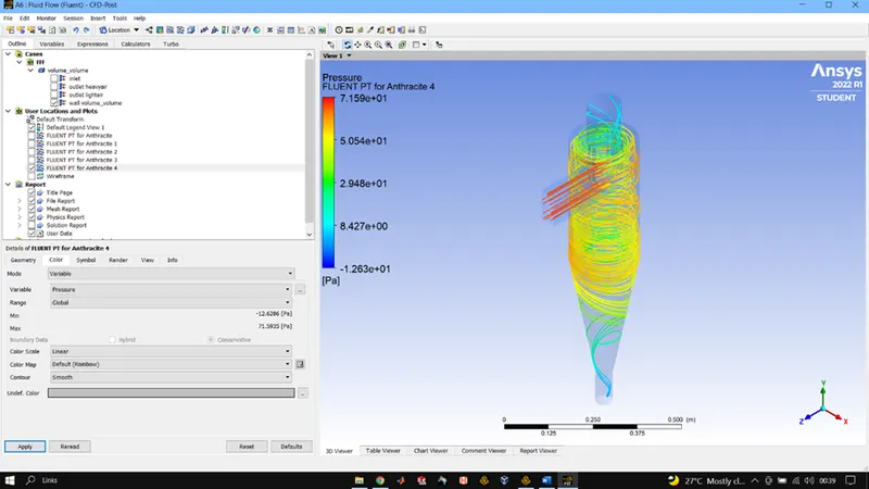
5mu1m/s
DPM Iteration ....
number tracked = 378, escaped = 104, trapped = 10, incomplete = 264
Separation efficiency = 2.64%
Pressure drop = 2.2535
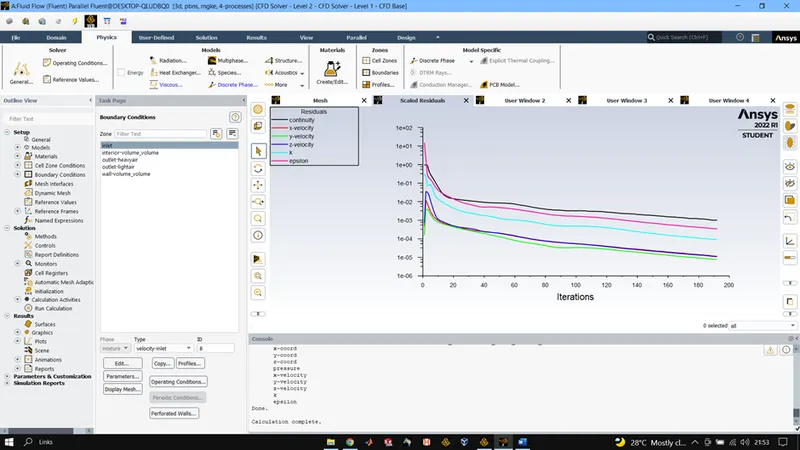
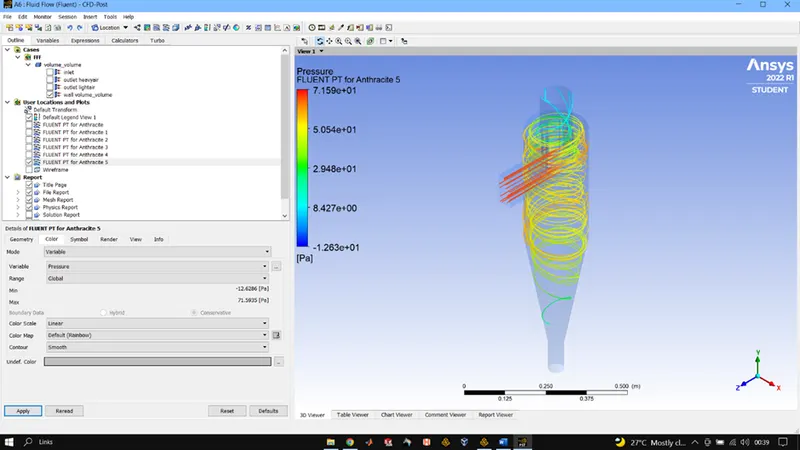
5mu2m/s
DPM Iteration ....
number tracked = 378, escaped = 98, trapped = 14, incomplete = 266
Separation efficiency = 3.70%
Pressure drop = 11.84
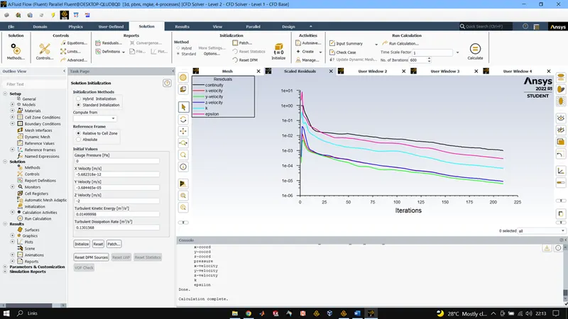
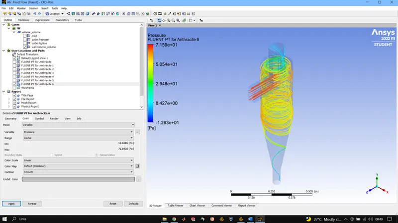
5mu4m/s
DPM Iteration ....
number tracked = 378, escaped = 90, trapped = 286, incomplete = 2
Separation efficiency = 75.66%
Pressure drop = 50.105
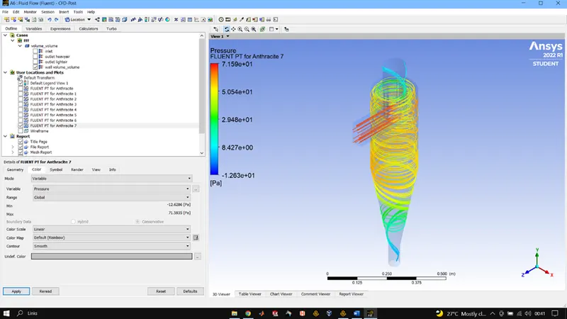
5mu5m/s
DPM Iteration ....
number tracked = 378, escaped = 99, trapped = 277, incomplete = 2
Separation efficiency = 73.28%
Pressure drop = 80.08
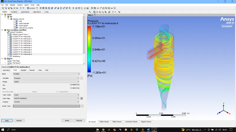
CONCLSUION : There are several factors that can affect a cyclone separators efficiency. These include particle density, particle size, volumetric flow rate, pressure drop, cone length, body length, ratio of accept port to body diameter, and even the smoothness of the cyclone's internal surfaces.
The pressure drop over in a cyclone separator is caused by the area changes, the wall friction, change of the flow direction and the dissipation in the vortex.