Week 8 - Simulating Cyclone separator with Discrete Phase Modelling
Aim : To perform analysis on cyclone separator and calculate the separation efficiency and pressure drop.
Objective :
- To write a few words about any four empirical models used to calculate the cyclone separator efficiency.
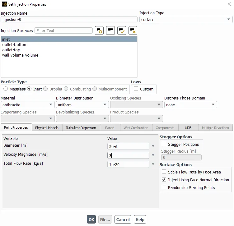
- To perform an analysis on a given cyclone separator model by varying the particle diameter from 1 μm to 5 μm and calculate the separation efficiency in each case. Discuss the results. [Use both the velocity's as 3m/sec.]
- To perform an analysis on a given cyclone separator model by varying the particle velocity from 1 m/sec to 5 m/sec and calculate the separation efficiency and pressure drop in each case. Discuss the results. [Use particle diameter size as 5 μm for all cases & keep flow velocity same as particle velocity]
Boundary Conditions :
- Inlet and wall - Reflect
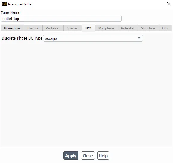
- Outlet of Top - Escape
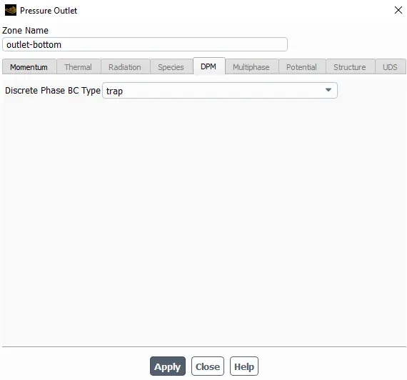
- Outlet of bottom - Trap
Cyclone Sepereator :
Cyclone separators work much like a centrifuge, but with a continuous feed of dirty air. In a cyclone separator, dirty flue gas is fed into a chamber. The inside of the chamber creates a spiral vortex, similar to a tornado. The lighter components of this gas have less inertia, so it is easier for them to be influenced by the vortex and travel up it. Contrarily, larger components of particulate matter have more inertia and are not as easily influenced by the vortex.
EMPIRICAL MODELS FOR THE PREDICTION OF CYCLONE EFFICIENCY :
- Lapple Model
- Koch and Licht Model
- Li and Wang Model
- Iozia and Leith Model
- Lapple Model
Lapple model was developed based on force balance without considering the flow resistance. Lapple assumed that a particle entering the cyclone is evenly distributed across the inlet opening. The particle that travels from inlet half width to the wall in the cyclone is collected with 50% efficiency.
The Efficiency of collection of any size of the particle = `eta_i` = `1/(1+(d_(pc)/d_(p_i))^2`
- Koch and Licht Model
Koch and Licht (1977) collection theory recognized the inherently turbulent nature of cyclones and the distribution of gas residence times within the cyclone. Koch and Licht describe particle motion in the entry and collection regions with the additional following assumptions:
- The tangential velocity of a particle is equal to the tangential velocity of the gas flow.
- The tangential velocity is related to the radius of cyclone by: u Rn = constant.
The grade efficiency is given by `eta_i` = `1-exp(-2*((G*tau_i*Q)/D^3*(n+1))^(0.5/(n+1)))`
- Li and Wang Model
The Li and Wang model includes particle bounce or re-entrainment and turbulent diffusion at the cyclone wall. A two-dimensional analytical expression of particle distribution in the cyclone is obtained.
`eta_i` =`1-exp(-lambdatheta_1)`
- Iozia and Leith Model
Iozia and Leith logistic model is a modified version of Barth model which is developed based on force balance. The model assumes that a particle carried by the vortex endures the influence
of two forces: a centrifugal force, Z, and a flow resistance, W.
`eta_i` = `1/(1+(d_(pc)/d_(p_i))^beta`
Modelling Approach :
For this analysis we use the Cyclone Separator which provide a method of removing particular matter from air or other gas streams at low cost and low maintenance. For this case we use the Discrete phase Modelling (DPM) Setup in the Ansys Fluent for the simulation.
There are 2 phases as given Below :
- Continuous Phase: It consists of Fluid flowing within the Fluid Volume.
- Discrete Phase: It consists of smaller particles interacting with continous Phase and It also exchange momentum, mass and energy with fluid phase or continous phase.
In the Discrete Phase Modelling (DPM) we have two ways to carried out DPM
- Uncoupled-flow: In this type of flow, Discrete Phase will not interact with the continous Phase.
- Coupled-flow: It will influence the flow of continous phase.
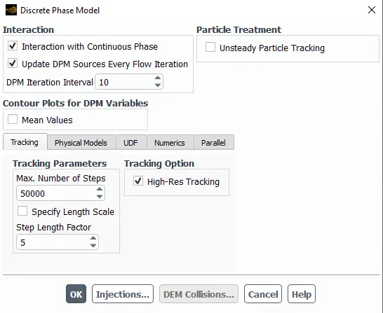
For, this analysis we have used the coupled-flow in DPM to get accurate results.
The collection efficiency of cyclones varies as a function of density, particle size and cyclone design. Cyclone efficiency will generally increase with increases in particle size and/or density; inlet duct velocity; cyclone body length; number of gas revolutions in the cyclone; ratio of cyclone body diameter to gas exit diameter; inlet dust loading; smoothness of the cyclone inner wall. To check the effect on the Separation efficiency we will perform an analysis on given Cyclone model in two different manners.
- By varying Particle diameter: from 1 μm to 5 μm.
- By varying Particle Velocities: from 1m/s to 5m/s.
Solving Approach :
Geometry :
- Import the Geometry in fluent spaceclaim, named as Cyclone Separator.stp
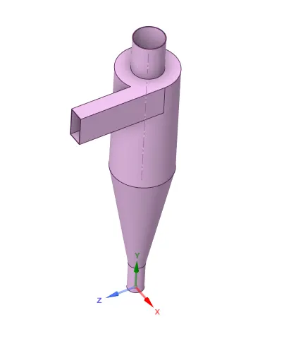
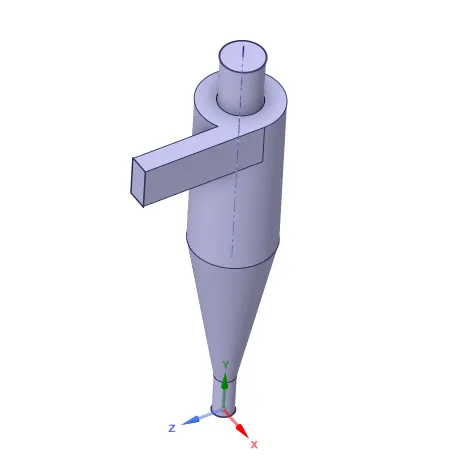
- Then Extract the Fluid Volume by selecting the inner edges at Inlet and Outlet's of the geometry.
- After that Hide the Geometry and Supress it for Physics.
- Save the Fluid Volume for further Processes.
Meshing :
- Create named selection
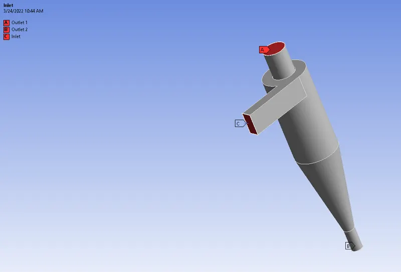
-
Generate Mesh
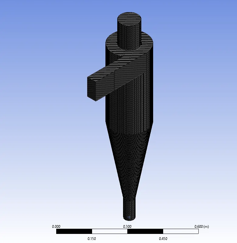
Here, the Geometry of Cyclone separator is simple and we are using Structrual Mesh because it gives the best results.
The element size is 5 mm and no. of elements = 424483
Fluent Setup :
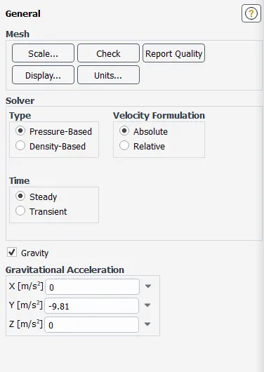
- General
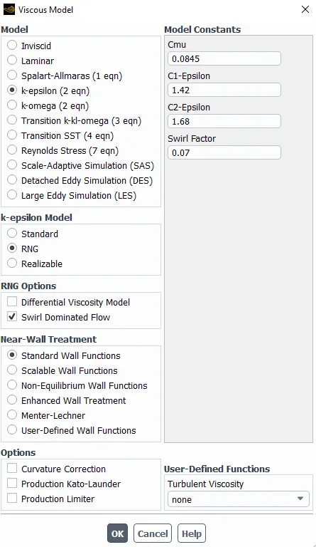
- Viscous model
- Discrete Phase model
- Injection Parameter
- Inlet Condition
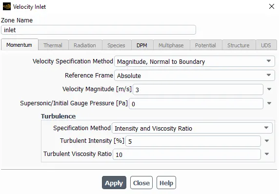
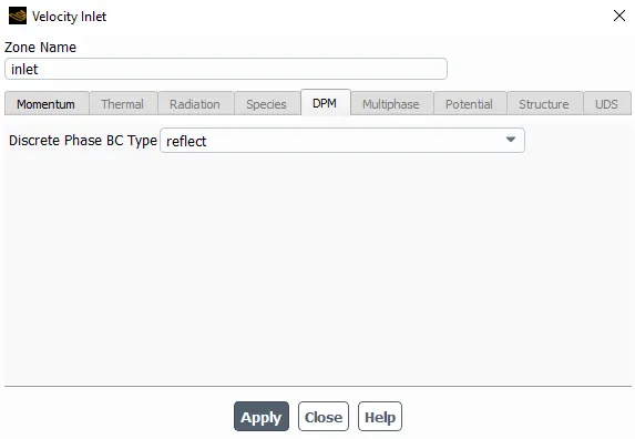
- Top outlet
- Bottom outlet
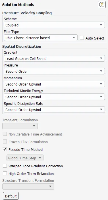
- Solution Method
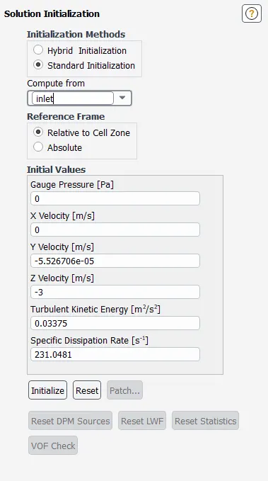
- Initialization
Results :
PART A : By varying Particle diameter : from 1 μm to 5 μm.
| Case | Particle Size (μm) | Particle and flow velocity (m/s) |
| 1 | 5 | 3 |
| 2 | 3 | 3 |
| 3 | 1 | 3 |
Case 1 :
Particle size = 5 `mum`
Particle and flow velocity = 3 m/s
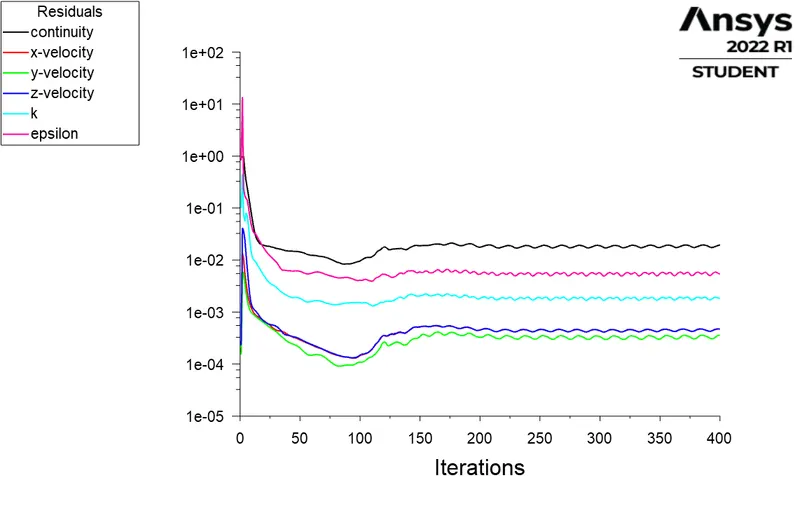
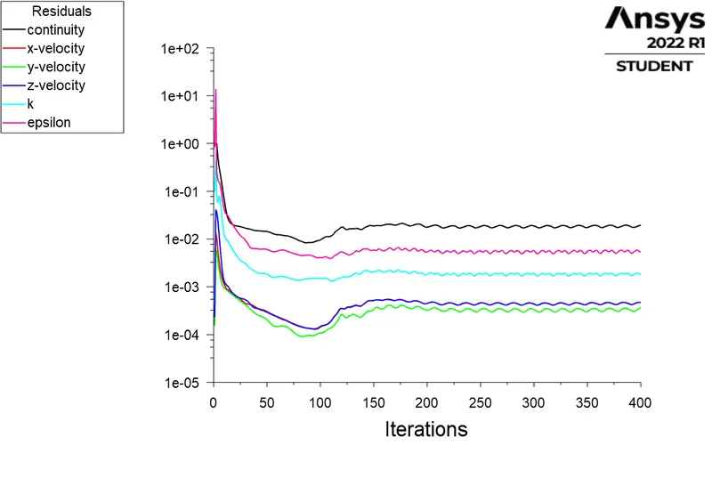
Residuals :
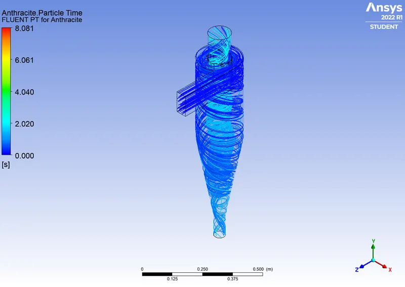
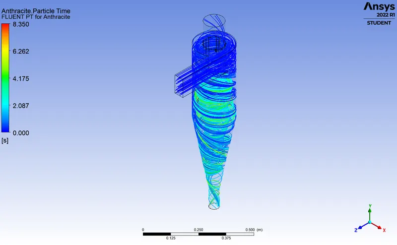
Particle Resident Time :
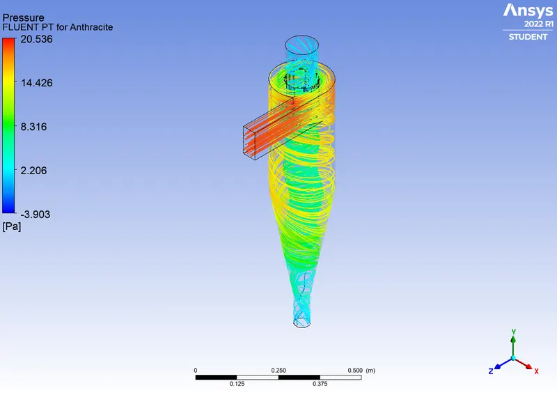
Pressure :
Efficiency :
Number tracked = 378, escaped = 108, trapped = 270
Separation Efficiency = (No. of Particles Trapped)/ (No. of Particles Tracked)
Separation Efficiency = (270/378)*100
Separation Efficiency = 71.42%
Pressure Difference :
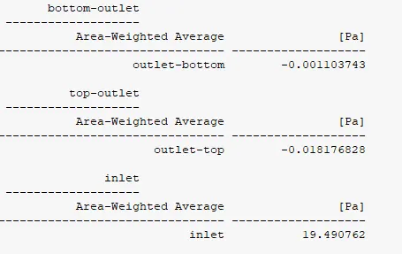
Pressure Difference = Pressure at Inlet - (Pressure at Oulet 1 + Pressure at Oulet 2)
Pressure Difference = 19.490762-(0.01817+0.001103)
Pressure Difference = 19.4714 Pa
Case 2 :
Particle size = 3 `mum`
Particle and flow velocity = 3 m/s
Residuals :
Particle Resident Time :
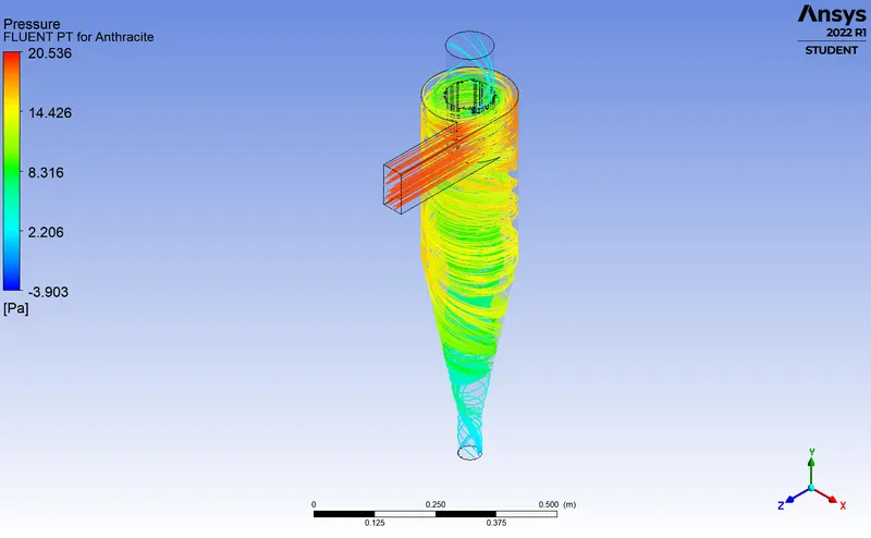
Pressure :
Efficiency :
Number tracked = 378, escaped = 142, trapped = 236
Separation Efficiency = (No. of Particles Trapped)/ (No. of Particles Tracked)
Separation Efficiency = (236/378)*100
Separation Efficiency = 62.43%
Pressure Difference :
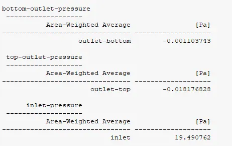
Pressure Difference = Pressure at Inlet - (Pressure at Oulet 1 + Pressure at Oulet 2)
Pressure Difference = 19.490762-(0.01817+0.001103)
Pressure Difference = 19.4714 Pa
Case 3 :
Particle size = 1 `mum`
Particle and flow velocity = 3 m/s
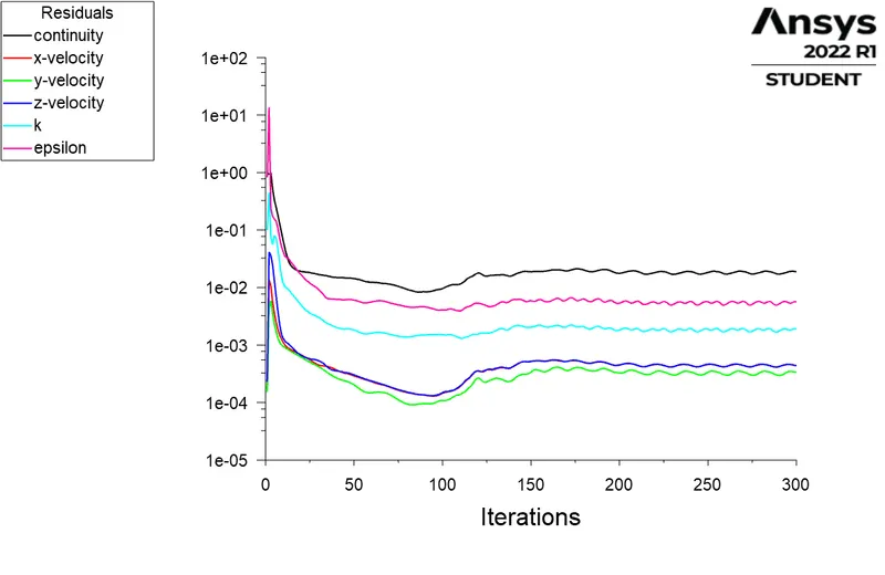
Residuals :
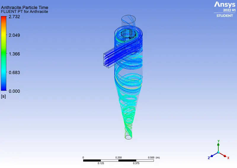
Particle Resident Time :
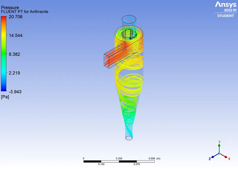
Pressure :
Efficiency :
Number tracked = 378, escaped = 166, trapped = 212
Separation Efficiency = (No. of Particles Trapped)/ (No. of Particles Tracked)
Separation Efficiency = (212/378)*100
Separation Efficiency = 56.08%
Pressure Difference :
Pressure Difference = Pressure at Inlet - (Pressure at Oulet 1 + Pressure at Oulet 2)
Pressure Difference = 19.490762-(0.01817+0.001103)
Pressure Difference = 19.4714 Pa
PART B : By varying Particle velocities : from 1 m/s to 5m/s.
| Case | Particle Size (μm) | Particle and flow velocity (m/s) |
| 1 | 5 | 5 |
| 2 | 5 | 3 |
| 3 | 5 | 1 |
Case 1 :
Particle size = 5 `mum`
Particle and flow velocity = 5 m/s
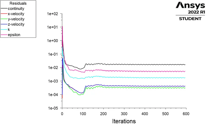
Residuals :
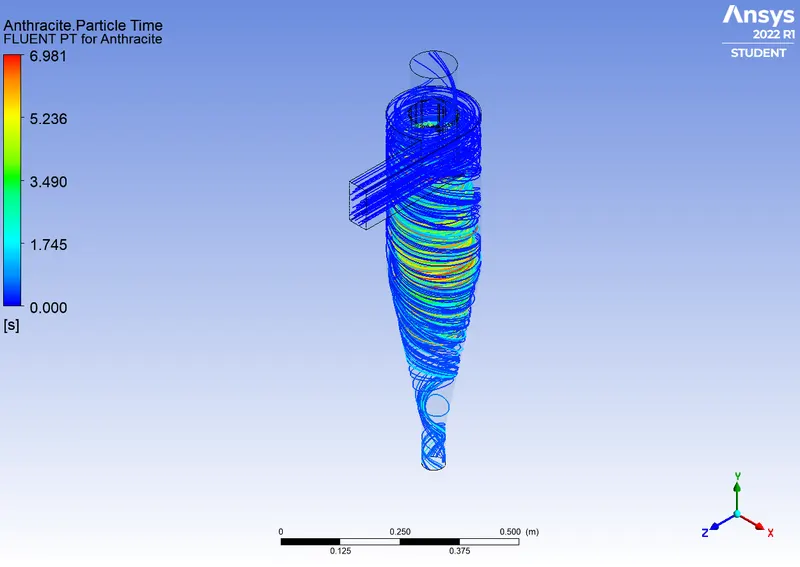
Particle Resident Time :
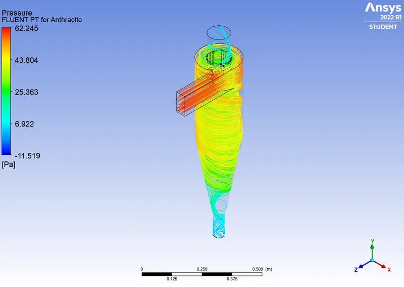
Pressure :
Efficiency :
Number tracked = 378, escaped = 78, trapped = 300
Separation Efficiency = (No. of Particles Trapped)/ (No. of Particles Tracked)
Separation Efficiency = (300/378)*100
Separation Efficiency = 79.36%
Pressure Difference :
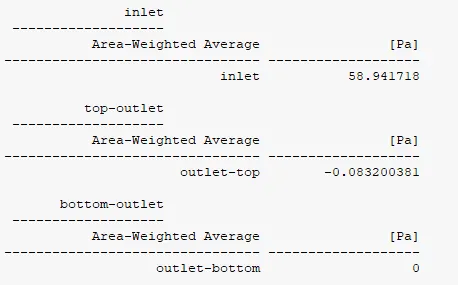
Pressure Difference = Pressure at Inlet - (Pressure at Oulet 1 + Pressure at Oulet 2)
Pressure Difference = 58.9417-(0.0832+0)
Pressure Difference = 58.8585 Pa
Case 2 :
Particle size = 5 `mum`
Particle and flow velocity = 3 m/s
Residuals :
Particle Resident Time :
Pressure :
Efficiency :
Number tracked = 378, escaped = 108, trapped = 270
Separation Efficiency = (No. of Particles Trapped)/ (No. of Particles Tracked)
Separation Efficiency = (270/378)*100
Separation Efficiency = 71.42%
Pressure Difference :
Pressure Difference = Pressure at Inlet - (Pressure at Oulet 1 + Pressure at Oulet 2)
Pressure Difference = 19.490762-(0.01817+0.001103)
Pressure Difference = 19.4714 Pa
Case 3 :
Particle size = 5 `mum`
Particle and flow velocity = 1 m/s
Residuals :
Particle Resident Time :
Pressure :
Efficiency :
Number tracked = 378, escaped = 146, trapped = 232
Separation Efficiency = (No. of Particles Trapped)/ (No. of Particles Tracked)
Separation Efficiency = (232/378)*100
Separation Efficiency = 61.37%
Pressure Difference :
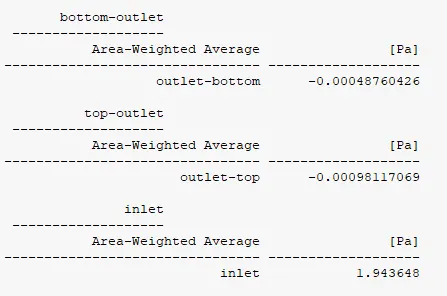
Pressure Difference = Pressure at Inlet - (Pressure at Oulet 1 + Pressure at Oulet 2)
Pressure Difference = 1.9436-(0.00098+0.00048)
Pressure Difference = 1.9421 Pa
COMPARISON BETWEEN THE RESULTS :
PART A : By varying Particle diameter : from 1 μm to 5 μm.
| Case | Particle Size (μm) | Particle and flow velocity (m/s) | Separation Efficiency(%) | Pressure Diff (pa) |
| 1 | 5 | 3 | 71.42 | 19.4714 |
| 2 | 3 | 3 | 62.43 | 19.4714 |
| 3 | 1 | 3 | 56.08 | 19.4714 |
PART B : By varying Particle velocities : from 1 m/s to 5m/s.
| Case | Particle Size (μm) | Particle and flow velocity (m/s) | Separation Efficiency(%) | Pressure Diff (pa) |
| 1 | 5 | 5 | 79.36 | 58.8585 |
| 2 | 5 | 3 | 71.42 | 19.4714 |
| 3 | 5 | 1 | 61.37 | 1.9421 |
Conclusion :
- From the above Table we can see that the Efficiency of cyclone Separator is increased with the Diameter of Particle and Velocity is increases.
- In Part_A we can see that the Efficiency increases in gradual manner with increase in the diameter of Particles It is Because the larger the Particle diameter higher Inertia, hence chance of escaping the Particle's is reduced.
- In Part_B we can observe that the Separation Efficiency Increases rapidly with increase in the Velocity but in the Pressure Drop It may varry because The total pressure drop in a cyclone will be due to the entry and exit losses, and friction and kinetic energy losses in the cyclone. Normally most significant pressure drop occurs in the body due to swirl and energy dissipation.
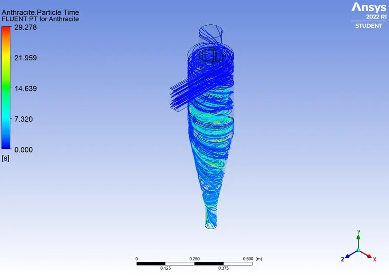
- Particle Resident time for both the cases Part_A and Part_B decreases with Increase in the Diameter of Particle and injection Velocity of Particles.
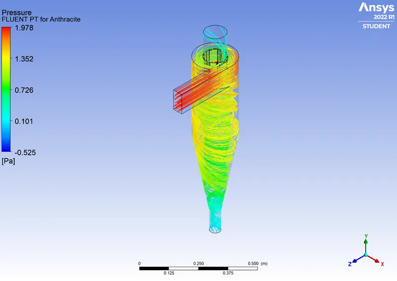
- We can see that in the Pressure contours for all cases velocity is high at the Inlet, It is because the Particle are Injected forcefully by the Inlet.
- In the Pressure Contours we can Also see that Pressure is high at Inlet and the Outer surface of the Cyclone Separator and Low at the Bottom of the Cyclone Separator It is because, when the Particle's travles in the swirl motion from the Inlet to the bottom the centrifugal force imparted at the outer surface of the cyclone and then the Particle's thrown from axial to radial direction and dur to that pressure at the Outer surface is more.
- We can Conclude that the Higher the Velocity, Higher the Pressure Drop and the Highest Efficiency.