Week 8 - Simulating Cyclone separator with Discrete Phase Modelling
AIM :- To perform analysis on cyclone separator and calculate the separation efficiency and pressured drop.
INTRODUCTION
cyclone separator are separation devices that use the principle of inertia to remove particulate matter from flue gases.cyclone separators is one of many air pollution control devices from known as pre-cleaners since they generally remove larger pieces of particulate matter. This prevents finer filteration methods from having to deal with large.More abrasive particles later on.In addition ,several cyclone separators can operate in parallel , and this system is known as a multicyclone.
It is important to note that cyclones can vary drastically in their size.The size of the cyclone depends largely on how much flue gas must be filtered thus larger operation tend to need larger cyclones.For example several different models of one-cyclone type can exit.and the sizes can range from a relatively small 1.2 -1.5 meters fall to around 9 meters.
components and design
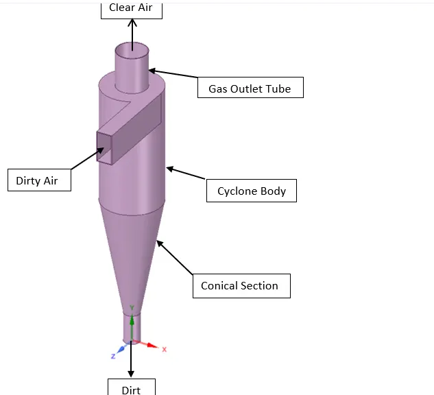
A reverse flow cyclone separator is an industrial assembly with no moving parts and a simple design.
The main cylindrical part of the cyclone separator is known as the body.The gradually narrowing conical section is known as core.Untreated gas enters tangentially through the inlet at the side of the separation . Entrained particles within the gas stream are separated from the gas steam and discharged through the reject port at the base of the separator.cleaned gas exits through the accept port at the top of separator.
WORKING
Cyclonic separation is meansof separating different liquid phases(different liquid densities) or separating particles from a gas stream.cyclone separatorsoften from part of a pre-cleaning stage prior to a gas or liquid being discharged.
cyclone separators work much like a centrifuge.(A centrifuge works by spining objects around a centro axix.The spining pushes harder on dense material than on less dense material which separates objectby their densities). but with a continuous feed of dirty air.In a cyclone separator dirty fluegas is fed into a chamber.
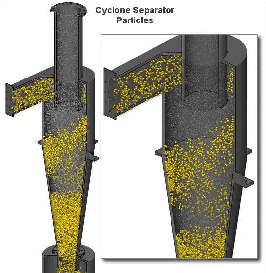
The inside of the chamber creates a spiral vortex.The lighter components of this gas have less inertia.so it is easier for them to be influenced by the vortexand travel up it contrainly , larger componentsof particluate
matter have more inertia and are not as easily influece by the vortex.
since these larger particles have difficulty following the high-speed spiral motion of the gas and the vortex ,the particles hit the inside walls of the container and drop down into a collection hopper. These chamber are shaped like an uprisal -down cone to promote the collection of these particles at the bottom of the container.The cleaned flue gas escapes out the top of the chamber .
Most cyclones are built to control and remove particulate matter that is larger than 10 micrometer in diameters.However there do exist high - efficiency cyclones that are designed to be effective on particles as small as 2.5 micrometers.As wall these separator arenot effective on extremly large particulate matter. For particulates around 200 micrometer in size.gravity ,setting chamber or momentum separator area better option.
out of all of the particulate -control devices cyclone separators are among the least expansive.They are often used as a pre-treatment before the flue gas enters more effective pollution control devices.Therefore cyclone separators can be seen as "rough separator " before the flue gas reaches the fine filteration stages.
spiral formation and the separation
Gas containing entrained particles enters at a high velocity through the tangential inlet at the topof the cyclone. The gas flows into the cyclone body/barrel at a tangent and begins to flow in a circular downward spiral forwards the lower reject port,: This downward flowing spiral is referred to as a spiral vortex.
GEOMETRY
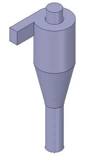
Fluid volume extracted using space claim
MESHING
MESH METRIC
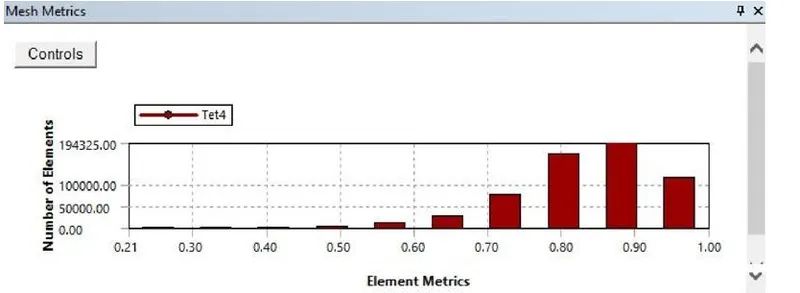
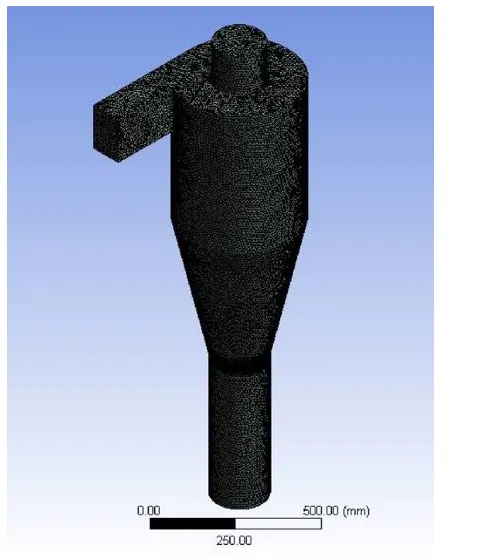
Size function: proximity & curvature
Min element size : 10mm
No of nodes:113728
No of elements: -59175 Boundary
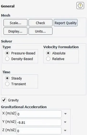
Gravity is enabled in the -ve y-direction
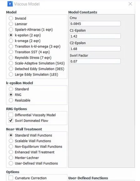
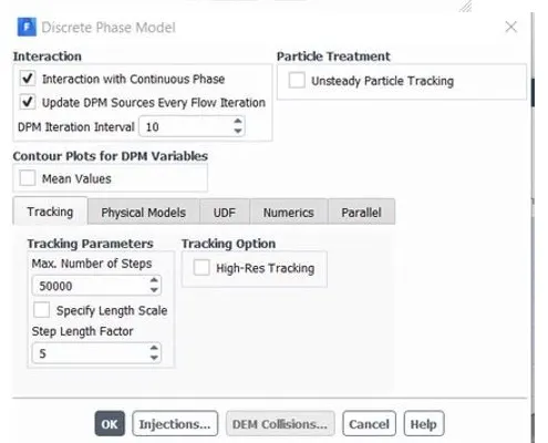
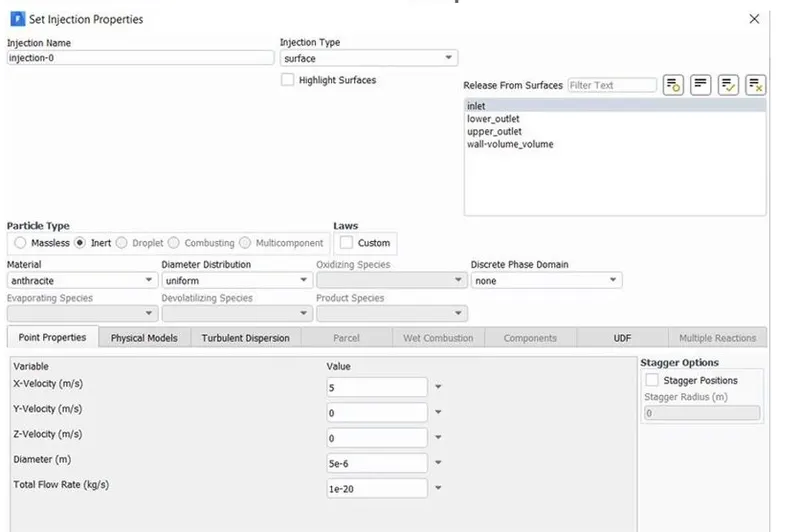
The swirl dominated RNG k - epsilon model is used to here to capture the flow more accurately.The discrete phase modelling is used to track the flow of theparticles.
No of step for particle tracking = 50000
Inspection Material:Anthracite (smicrons in diameter)
velocity inlet: 3m/s
outlet: Pressure outlet (Gauge Pressure Opa)
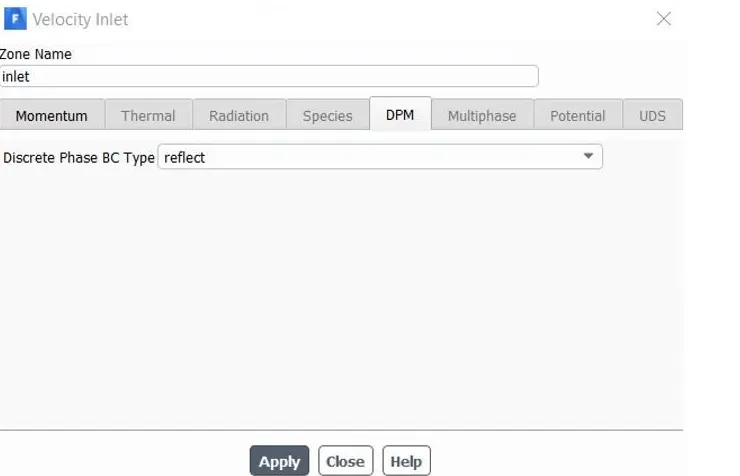
DPM setting are varied b/w reflect escape/ trap & wall jet.
Reflect: The particles rebounds off the boundary in question with a change in its momentum as defined by the co-efficient by restitution.
Escape:Particles escapes out when encountered by the boundary.
Trap: The trajectory calculation is terminated $ fate of the particle isrecorded asa trap.
Wall -Jet:- The Wall-jet type boundary condition is application for high-temperature walls where no significant liquid film is found $high weber no impacts when the spray act as a jet.This model is not applicable to regims where the filmis important.
SOLUTION APPROACH
RESULT
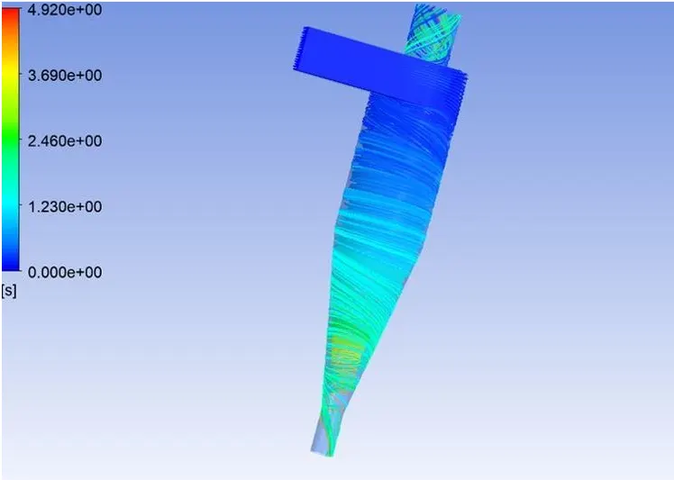
CASE 1: In this case we are mixing the velocity constant and we are visualizing the difference in results for different particle size.
Result for the particle size of 1 micron with a velocity of 3m/s.
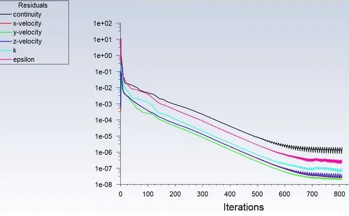
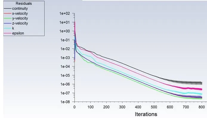
RESIDUAL PLOT
PRESSURE AT INLET
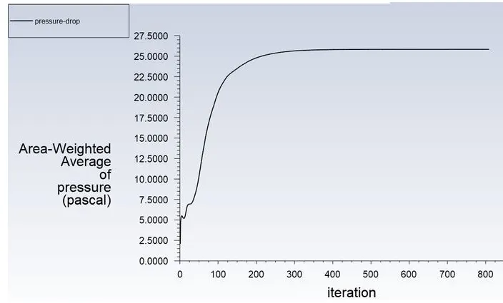
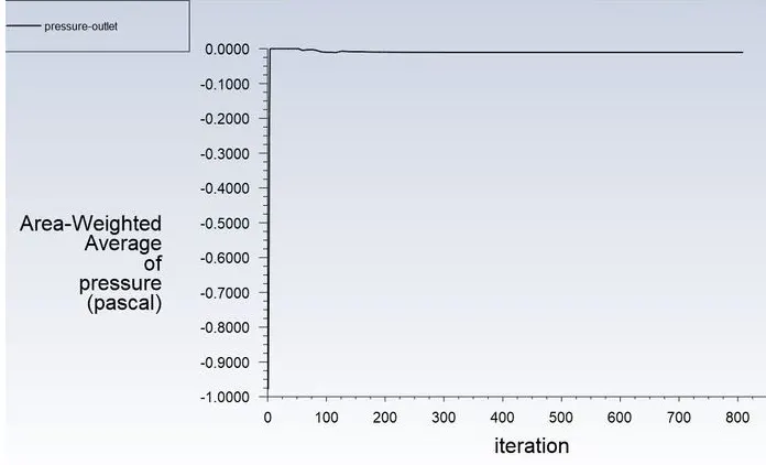
PRESSURE AT OUTLET

Separating efficiency= No.of particle trapped/No. of particles tracked
Separating Efficiency in % = (52/98)*100
separation Efficiency = 53.06%
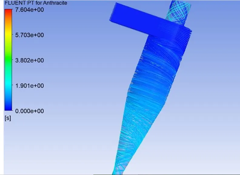
RESULT FOR THE PARTICLE OF 2 MICRON WITH A VELOCITY OF 3M/S
RESIDUAL PLOT
PRESSURE AT INLET
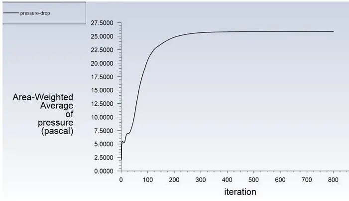
PRESSURE AT OUTLET
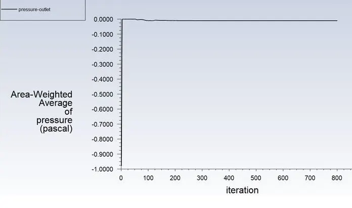

Separating efficiency= No.of particle trapped/No. of particles tracked
Separating Efficiency in % = (75/98)*100
separation Efficiency = 76.5%
RESULT FOR THE PARTICALSIZE OF 5 MICRON WITH A VELOCITY OF 3M/S
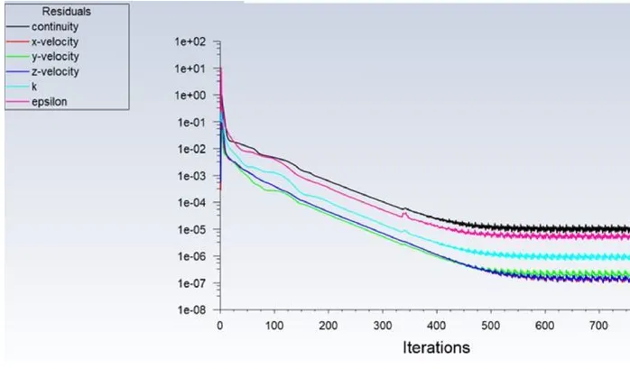
RESIDUAL PLOT
PRESSURE AT INLET
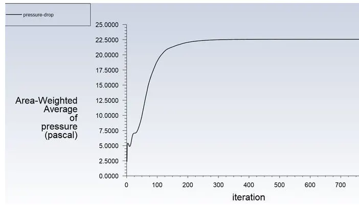
PRESSURE AT OUTLET
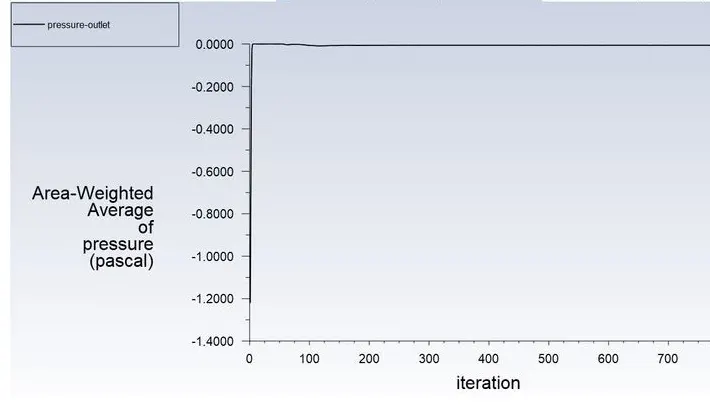
TOTAL PRESSURE
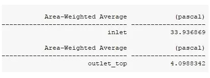
NOW
PRESSURE DROP = TOTAL INLET PRESSURE-TOTAL OUTLET PRESSURE
= 33.93-4.099
PRESSURE DROP = 29.83Pa
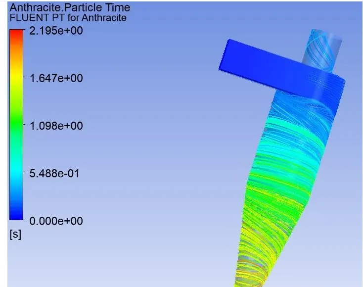
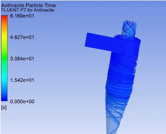
PARTICAL TRACKING

Separating efficiency= No.of particle trapped/No. of particles tracked
Separating Efficiency in % = (98/98)*100
separation Efficiency = 100%
inlet velocity of the particle and the discreate
CASE 2: Results for the varying velocity and keeping the particle size constanti.e 5 micron
inlet velocity of the particle and the discrete phase is samei.e 1m/s:
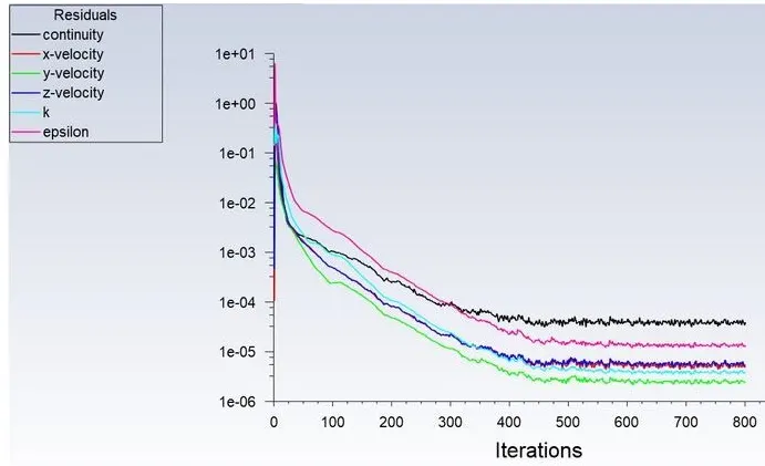
RESIDUAL PLOT
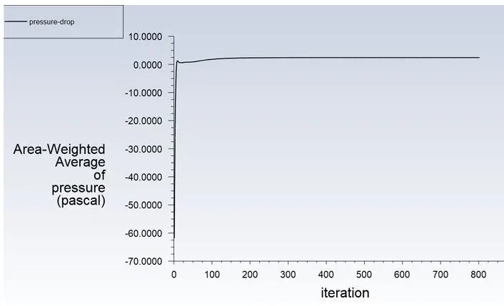
PRESSURE AT INLET
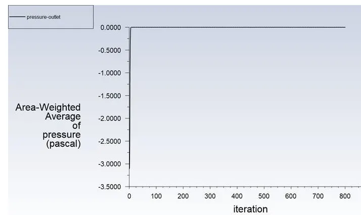
PRESSURE AT OUTLET
TOTAL PRESSURE
B1
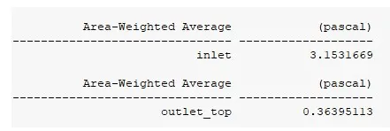
pressure drop = Total inlet pressure - Total outlet pressure
3.15-0.36
pressure drop = 2.79pa
PRACTICAL TRACKING
B1

Separating efficiency= No.of particle trapped/No. of particles tracked
Separating Efficiency in % = (7/98)*100
separation Efficiency = 7.14%
inlet velocity of the particle and the discreate
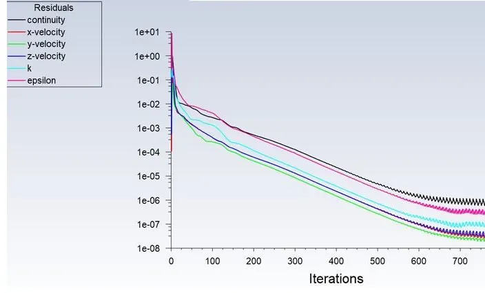
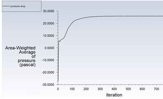
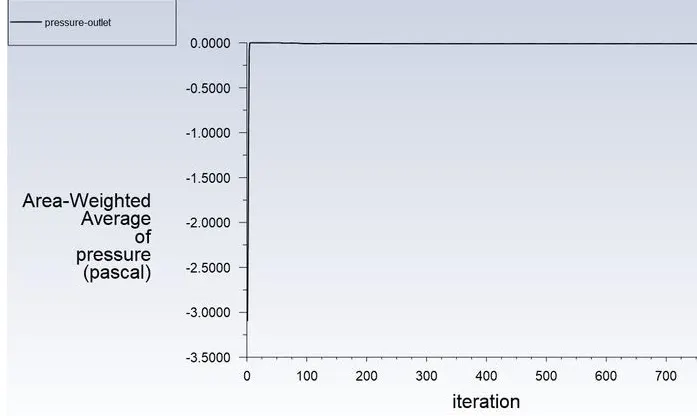
INLET VELOCITY OF THE PARTICAL AND THEDISCREATE PHASE IS SAME i.e 3m/s
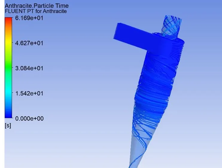
RESIDUAL PLOT
PRESSURE AT INLET
PRESSURE AT OUTLET
TOTAL PRESSURE
B3
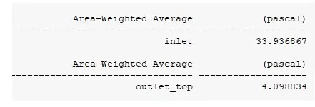
Pressure Drop = Total inlet pressur -Total outlet pressure
33.93-4.09
Pressure Drop = 29.83Pa
practical tracking
B3

Separating efficiency= No.of particle trapped/No. of particles tracked
Separating Efficiency in % = (98/98)*100
separation Efficiency = 100%
INLET VELOCITY OF THE PARTICLE AND THE DISCREATE PHASE IS SAME i.e5m/s
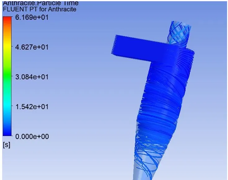
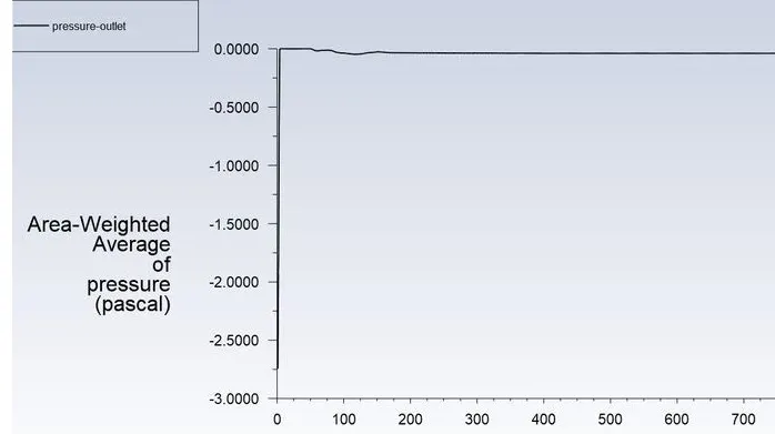
RESIDUAL PLOT
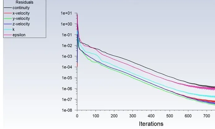
PRESSURE AT INLET
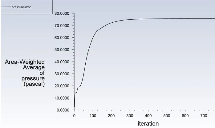
PRESSURE AT OUTLET
TOTAL PRESSURE
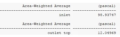
pressure drop =Total inlet pressure-total outlet pressure
98.93-12.04
pressure drop = 86.89Pa
PARTICAL TRACKING

Separating efficiency= No.of particle trapped/No. of particles tracked
Separating Efficiency in % = (98/98)*100
separation Efficiency = 100%
CONCLUSIOIN
1. Simulation is done for particle size varying from 1m to 5m with air and particle velocity as 3m/s.From the video ;it is observed that heavier particle is trapped at the bottom outlet and lighter particles are escaped at the outlet1. but we can also see that lighter particle also get trapped at bottom outlet because of interaction between lighter and heavier particles and there is an exchange of inertial forces.between them asa result there is a transfer of kinetic energy from heavier particle to the lighter particle ,as a result, we can observea certain number of heavier particles escapes through the top outlet.The collection efficiency of cyclones vanes as a function of particle size, density and cyclone design.
2.Cyclones efficiency will generally increase with the increase in particle size, density, inlet duct velocity,cyclone body length,number of gas revolution in the cyclone ,the ratrio of cyclone body diameter to gas exit diameter ,inlet dust loading,smoothness of the cyclone inner wall.
3. The efficiency of the cyclone will decrease with an increase in the parameters such as gas viscosity,cyclonebody diameter , gas exit diameter gas inlet duct area, gas density , leakage of air into dust outlet with the increase in inlet velocity or particle size the efficiency increases.
4.Pressure drop occurs because of the following components.
. Loss due to the expansion of gas in the cyclone chamber.
.Loss due to rotational kinetic energy.
. Loss due to wall frictional forces.