Week 8- Moving zones approach in Fluent
Objective:
- What are the approaches by which you would model moving zones?
- Which approach would you use to model unsteady phenomena?
- Simulate rotary motion for the geometry given
- Plot the velocity profile of the fluid motion
Answer:
Part 1:
To model the moving zones, two options are available which are moving reference zone & moving mesh approach.
Part 2:
To model unsteady phenomena, moving mesh approach is applicable out of the two.
Part 3:
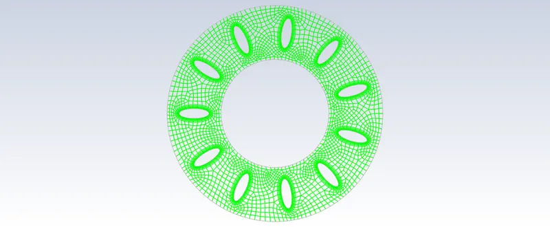
Given model with mesh as input:
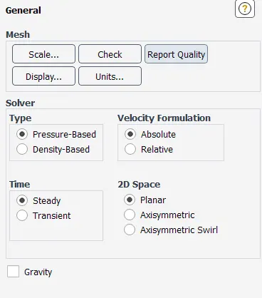
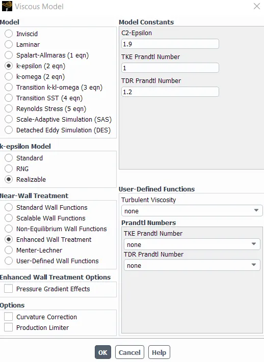
Viscous model: k-epsilon Realizable model with Enhanced wall treatment
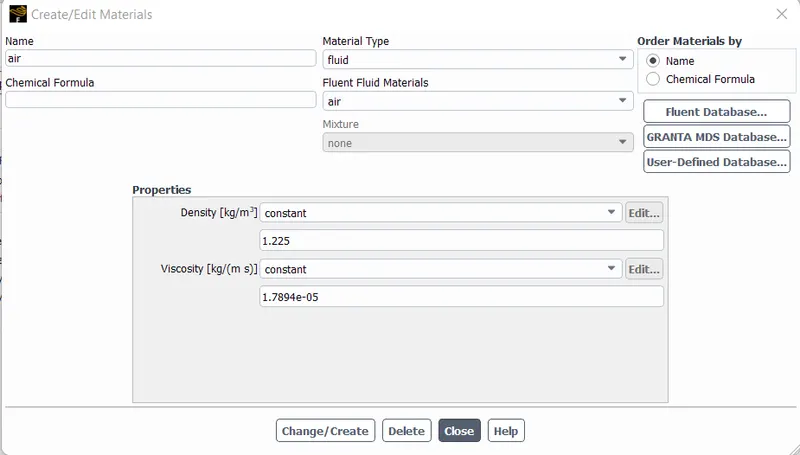
Material: Air
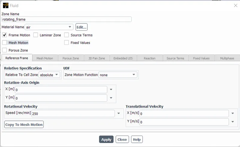
To implement Moving reference frame method, the "Frame motion" has been activated for air material & rotational velocity has been inserted as 250 rpm with default rotational-axis origin & translational velocity.
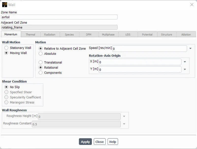
The activated moving reference fram option in previous step, has been assigned to the airfoil zone which was created by asigning to all the airfoil available in the part. Instead of stationary wall, the moving wall option was selected to indicate the moving zone with the "Relative to adjacent cell zone" option. And the angular velocity inserted in previous step will be applied to it as well as it has relative moment & also "Rotational" moment has also been activated.
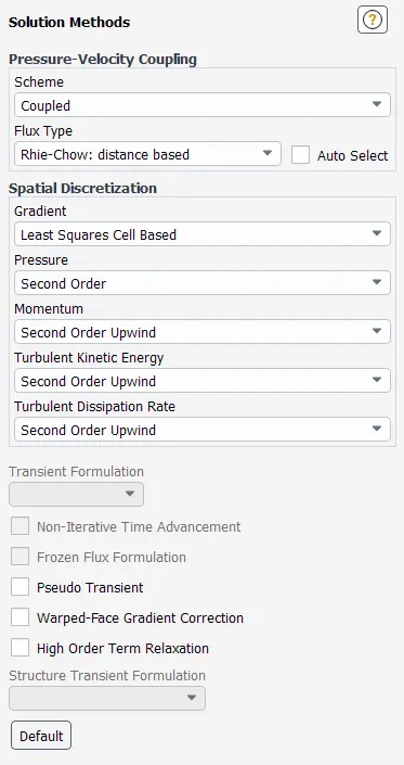
For Pressure-velocity coupling, the coupled method has been used with Second order upwind method for Turbulent kinetic energy and Turbulent dissipation rate. As Pseudo transient was not required for this simulation, it was turned off.
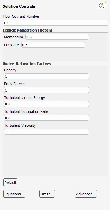
The flow courant number was chnaged from 200 to 10.
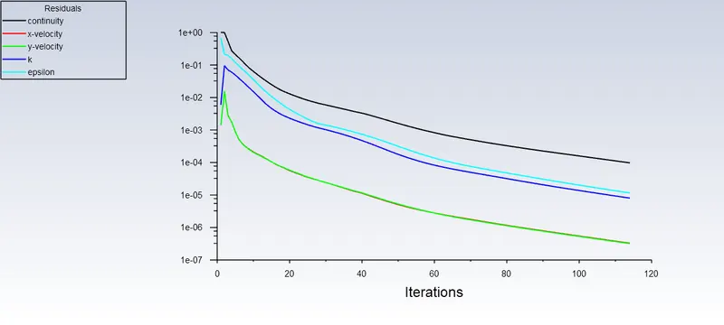
The convergence criteria was increased for this case from 1e-03 to 1e-04.
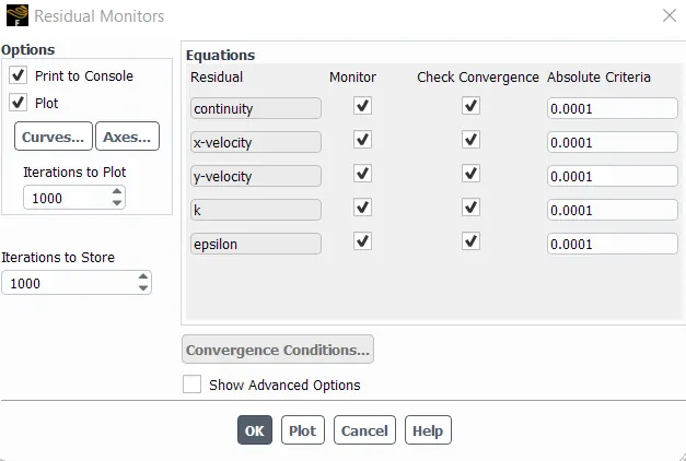
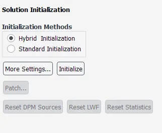
As inlet & outlet boundary conditions were unavailable, hybrid initialization has been used.
Results:
Residual Plot
Velocity Contour
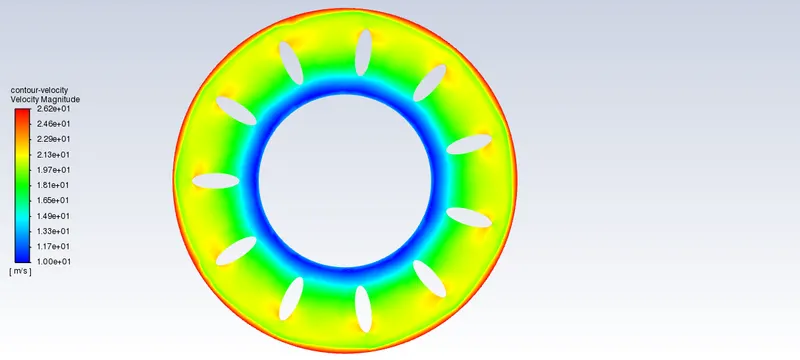
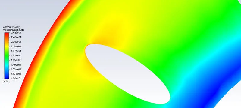
In velocity contour plots, it can be seen that the maximum velocity was detected at the outer frame while the region near to the inner frame had the lowest velocity. But by obesrving the airfoli edges, the top edge has faced the mximum velocity while the lower edge has the minimum velocity. And the velocity seperation can also be seen on top of the aifoil.