Week - 8 - Morphing
Morphing
AIM:-
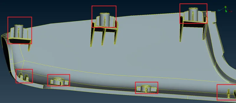
Perform morphing for the given Models and Increase the Height of the Dog houses and Ribs. (Refer Red annotations in the below image to understand what are Dog houses and Ribs) also Discuss applications of morphing in various industries.
INTRODUCTION:-
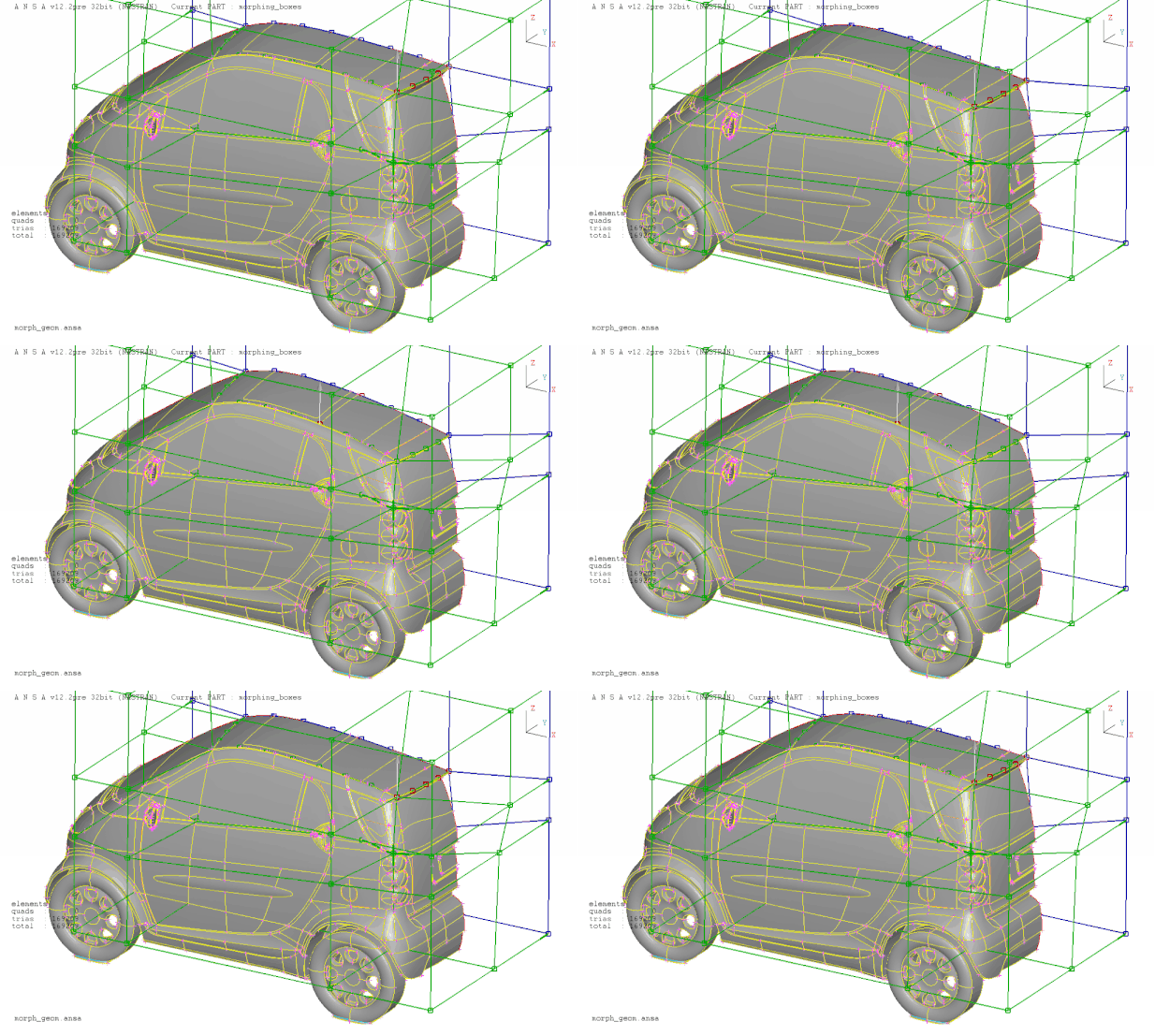
Morphing is an adaptation of a given shape to a new form which consists of manipulation of the parent design to convert or change it into some modified design. The geometry of a given concept model can be modified to required proportions to create new designs. CAE Morphing also allows users to work on the FE mesh directly reducing the time taken to go back to the designer to update the geometry. Basically morphing is changing the given shape to new acceptable form.
https://www.ansa-usa.com/wp-content/uploads/2015/05/ansa_morphing_02_small.gif
- Types of morphing:
Domain (Box) Morphing:-
Domain or Box Morphing is preformed With the help of boxes that are created around a particular part or assembly that the user wants to morph. The movement of the Morphing box control points defines the morphing operations on the entities inside the Morph box. This type of Morphing can be applied to both FE and Geometry based models.
Direct Morphing:-
ANSA’s Direct morphing features gives the user the ability to efficiently modify a part locally without having to create Morphing boxes. This method is extremely useful in creating local modifications on single parts. Creation of depressions, surface fitting certain FE part features to new target geometry, moving selected features along the contour of a surface and also the ability to freeze (rigid) elements during the morphing process are some of the direct morphing abilities.
Geometry Morphing:-
ANSA brings to the CAE world its ‘one – of – a kind’ tool for CAD geometry morphing. This pioneering concept allows the user to utilize the inventory of all the familiar FE morphing functions to perform equivalent operations in a CAD environment on geometric entities
- Applications of Morphing:
Automotive Industry
Electronic book illustrations
Education field
Computer Training centers
Movies
Animation Industry (Mostly Used)
Medical Field
Entertainment Industry
PROCEDURE:-
Model-1 -
(1) First of all Import the CAD model into ANSA software physical screen using following command.
ANSA.File > Open > Select the file
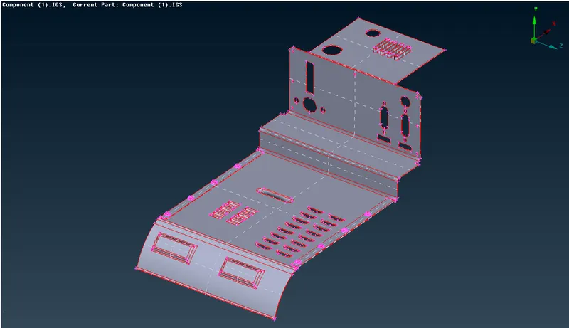
Fig: CAD Model
(2) After file importing, Topology is performed on the model and length between two adjacent hot points is changed to 1 from 20.
Topo Module > Faces > Topo > Box select the entire model > Middle mouse click
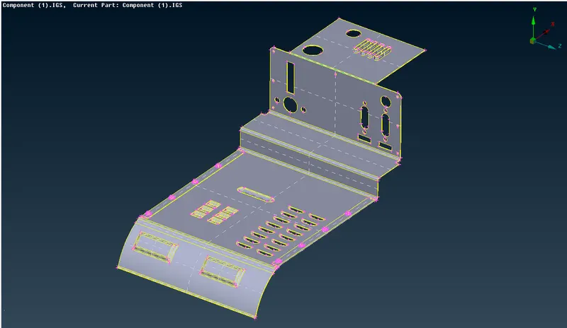
Fig: After Topo Performed
(3) Geometry checks and cleanup is performed after topology using checks manager and if any error is found then it is fixed either automatically by fix option otherwise using manual approach.
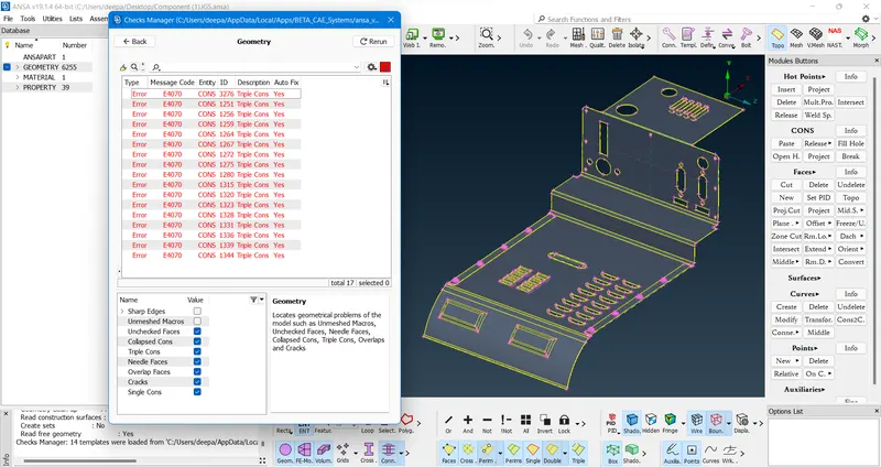
Fig: Before Applying Fixes
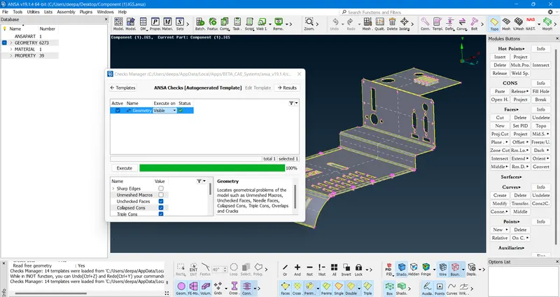
Fig: After Applying Fixes
(4) Following procedure is adopted for morphing.
The part to be morphed is isolated first and then go to Morph Module > Boxes > New > Ortho > Box Type - Ortho and Select - Geometry
Then select the part and give doble middle mouse click to confirm this will create a box around the part that was selected.
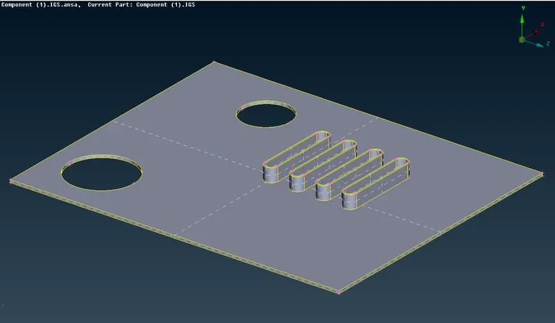
Fig: Isolated Part
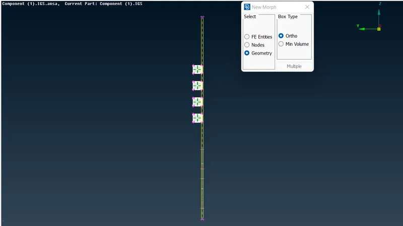
Fig: Selected Entities
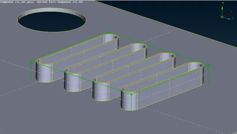
Fig: Box Formed
Now go to Box Morphing > Move. This will open a box then make local or natural co-ordinates on the face using single right mouse click and turn off the y and z co-ordinates in the box since we are only interested with increasing the height of the selected part as per the natural co-ordinates, this will allow the movement of control points in x direction only as shown.
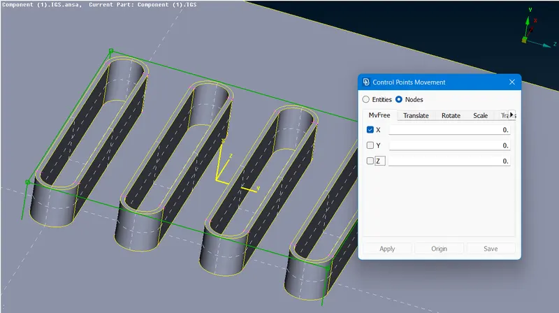
Fig: Natural Co-ordinates
Now select the control points of the box and give middle mouse click to confirm. After giving confirmation move the points in the x direction in order to increase the part height as per requirement and click the left mouse button to stop and then click on OK.
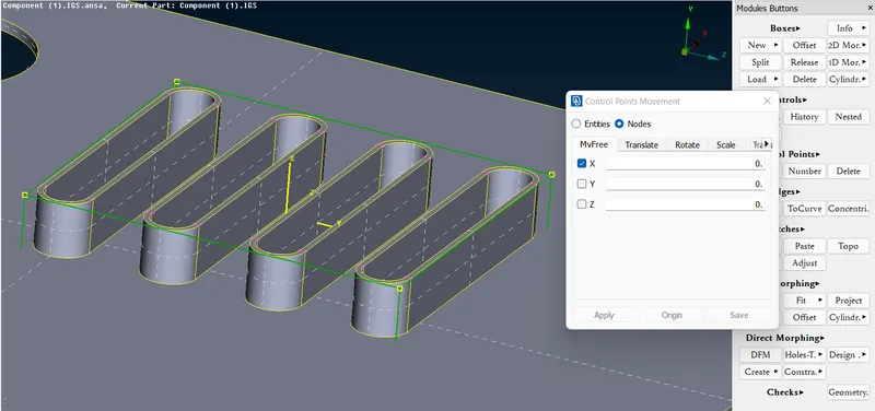
Fig: Control Points Selected
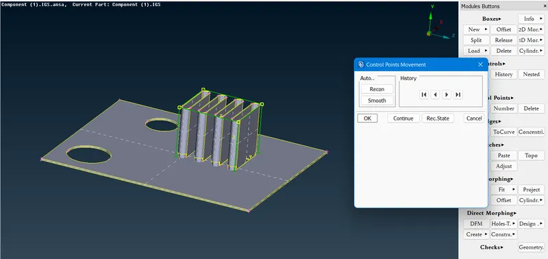
Fig: Movement of contrl points
Finally we have the part with increased height using morphing.
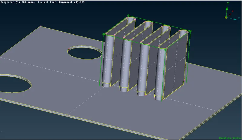
Fig: Final part with increased entities height
Same procedure can be adopted to alter the dimensions of any part.
Now we have the other part and we are willing to change the shape of this part.
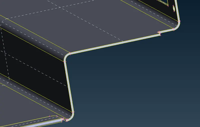
Fig: Part to be Morphed
So we again go to Boxes > New > Ortho and part faces are selected, then we select the control points of the box formed and move them in appropriate direction to get the desired shape.
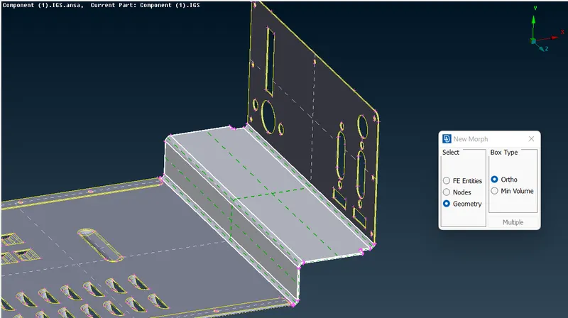
Fig: Selected part
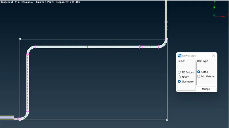
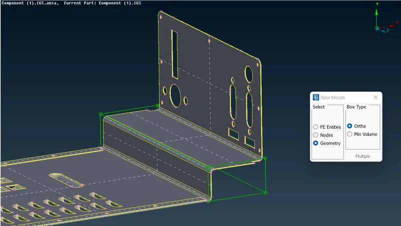
Fig: Box Formed
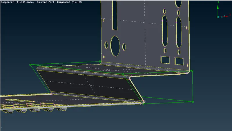
Fig: Altered shape
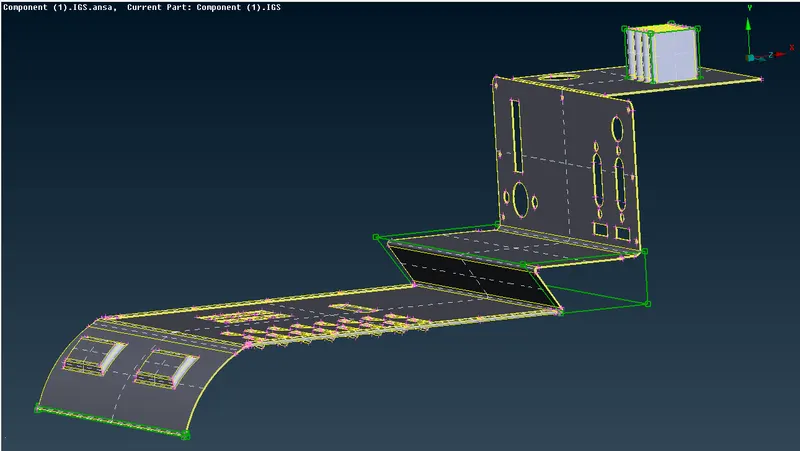
Fig: Final Morphed Model
Model-2 -
(1) Import the CAD model into ANSA Preprocessor environment and give topo on the model.
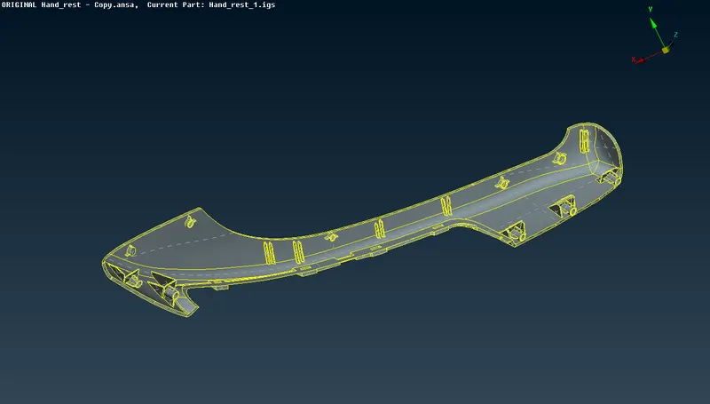
Fig: CAD Model After Topo
(2) Perform geometry checks on the model and remove if there is any of the errors exist.
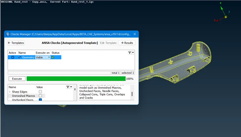
Fig: Model After Fixes Applied
(3) After that go to Morph Module > Boxes > New > Box Type - Min Volume and Select - Geometry > Select the rib or dog house > Double middle mouse click. This will create a box around the part as shown.
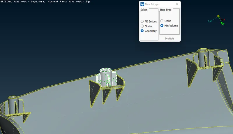
Fig: Selected part
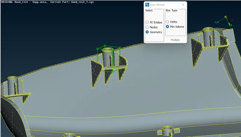
Fig: Green Box Created
(4) Now go to Box Morphing > Move > Create natural co-ordinates by clicking right mouse button > Select the control points and move then in y direction. This will increase the height of the part as shown.
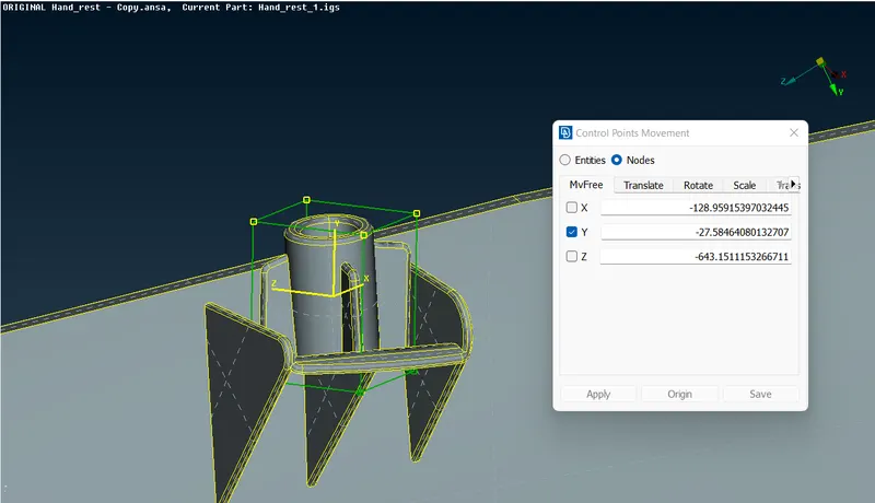
Fig: Control Points Selected
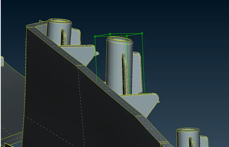
Fig: Part After Height Increment
(5) Same procedure is adopted for other entities and the final model that we get is given below after height increment.
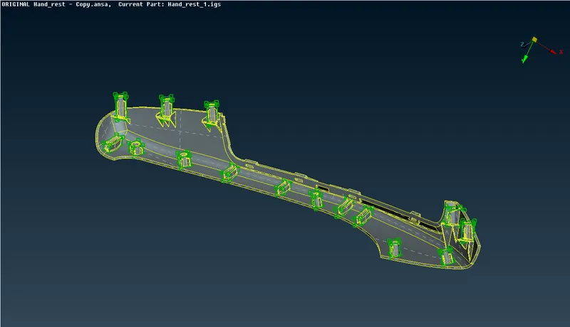
Fig: Final Model With All Height Increments
CONCLUSIONS:-
Successfully morphed the given model.
LEARNING OUTCOMES:-
- Learned about concept of morphing and it's types.
- Learned about hands on usage of Box Morphing
- Learned about geometrical adjustments of model using morphing and splitting up the morph box.