Week 8 Challenge
Calculate the centrifugal load for the following load data.
- The span of the bridge is 12 m.
- Width of carriage way is 7 m.
- The bridge is subjected to a live load of Class 70R tracked vehicle.
- The design speed of the vehicles is 75 km/hr.
- The radius of curvature in the bridge is 3 m
- Sol:-
INTRODUCTION:
Centrifugal Force A force, arising from the body's inertia, which appears to act on a body moving in a circular path and is directed away from the centre around which the body is moving.
The Moving of Vehicle in the curve produce a outer word pushing force from the bridge which exerts load on the structural element of the bridge centrifugal force.
AIM :- Calculate the centrifugal load on the bridge due to curve of 3 m radius ,the span of the bridge is 12 m and Carriage width is 7 m Live Load is 70 R
Data Given:-
Span of the Bridge = 12 m
Carriage width of bridge=7.00 m
Live Load= 70 R Tracked Vehicle
Design Speed = 75 KMPH
Radius of curvature= 3 m
Centrifugal Force on the Bridge = WV 2/ 127R
W = Single Track Load UDL of 70R track loading =350/4.570=76.58 KN/M
V = 75 KMPH
R = 3 m
CF= 76.58X75X75/127X3 = 1130 KN
We would like to model the bridge in the STAAD.pro as per given Data
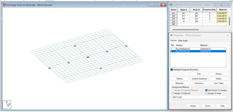
Fig 1 above
Model the slab with plate element of 0.5 m X0.5 M mess width of the brdige 10 m including 7.0 m carriage width and span of the bridge 12 m.
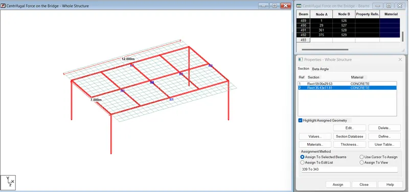
Fig 2 above
Three Main been have been provided at 3.5 m C/C and Cross beams have been assigned 3 m C/C and slab is resting on 4 columns.
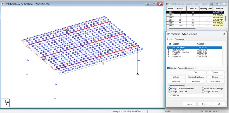
Fig 3 above
There are 3 Nos Longitudinal Girder section 0.75 m X1.5 m has been assigned.
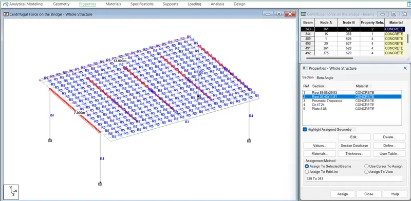
Fig 4 above
Cross Girder with section 0.3 m X 0.9 m at 3 m C/C distance.
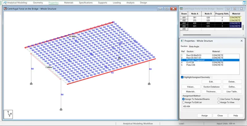
Fig 5 above
Super Imposed dead Load has been assigned as a Crash Barrier longitudinally along the slab at the edge of cantilever slab as shown in the fig.
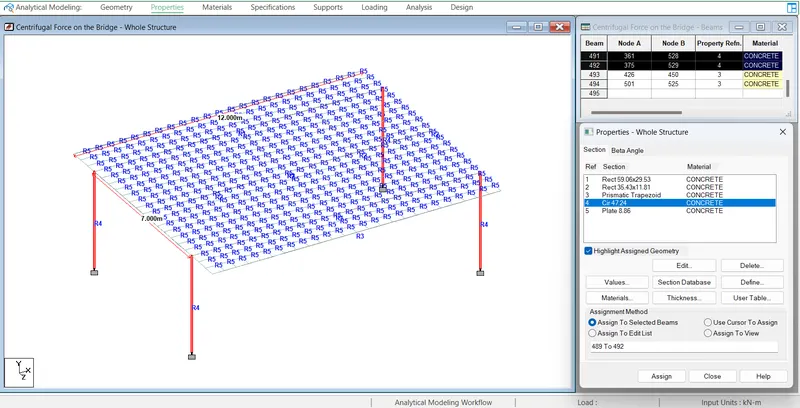
Fig 6
Section 1.2 m Circular Column has been assigned for piers and slab thickness of 0.225 m for slab as shown figh
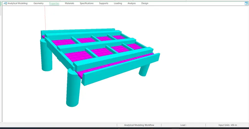
Fig 7
Three dimesions view of the bridge Model as shown in the Fig above
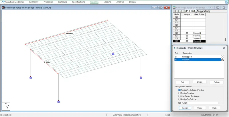
Fig 8
Fixed Supports have been assigned for the all Columns as shown in the Fig.
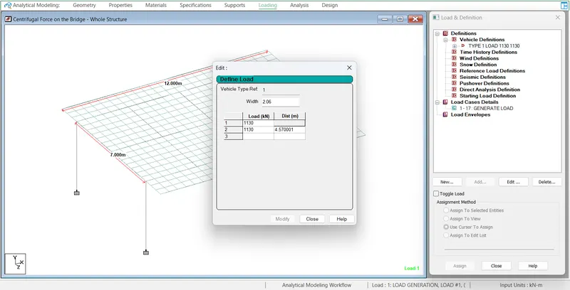
Fig 9
Live Load 70 R has been defined 1130 KN with centrifugal force as per above calculation with vehicle width 2.06 m and Load generation been considered as below
Load Generation = Vehicle Length +Bridge Length/Running Meter lenth
= 4.57+12/1=16.57 say 17 Nos as shown Fig.
The following checks have been carried out before go for Analysis and design.
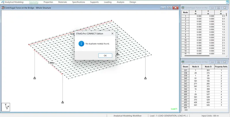
Fig 10
Checked for duplicate nodes with the help of utilities found OK no dublicate nodes.
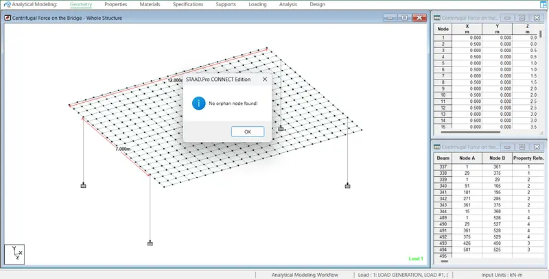
Fig 11
Checked for Orphan Nodes and found OK.
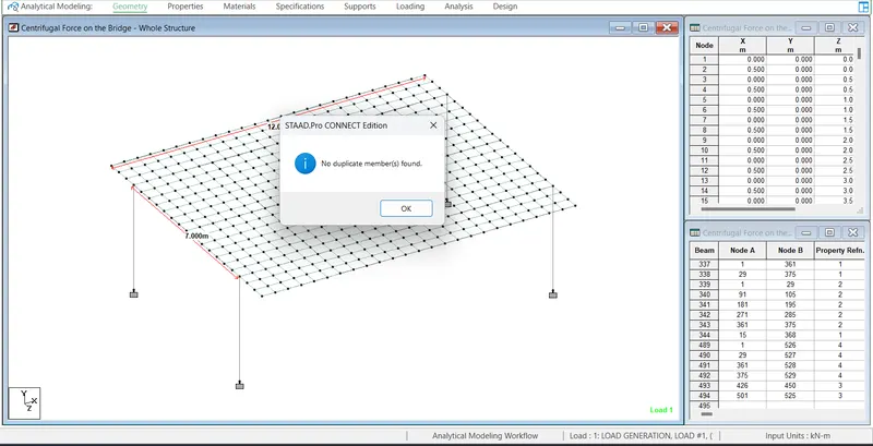
Fig 12
Checked for duplicate members and fond OK there no duplicate members.
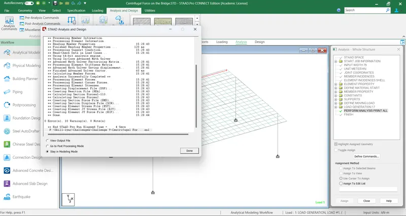
Fig 13.
Analysis has been done with Zero errors.
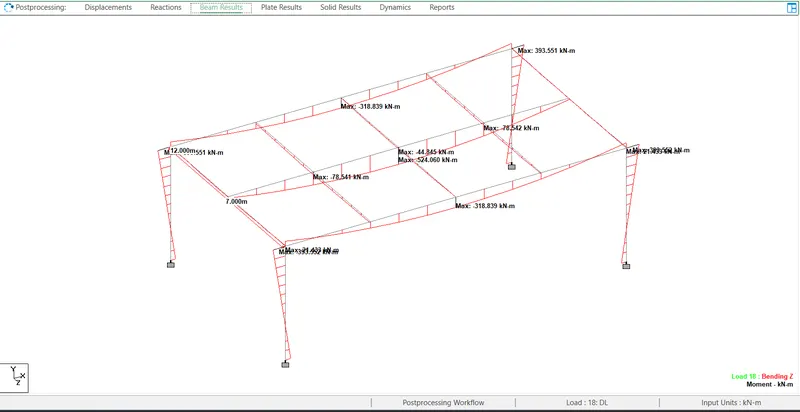
Fig 14
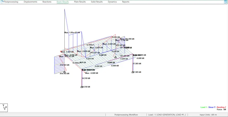
Results
Maximum Bending Moment middle beam 524 KN-m
Maximum Bending Moment of the Column = 393.5 KN-m
Maximum deflection = 16 mm
Maximum SF =159 KN