Week 8 Challenge
AIM and INTRODUCTION :
- To calculate the centrifugal load for the bridge subjected to a live load of class 70R loading and need to apply calculated centrifugal load in the bridge using staad pro.
- The centrifugal force is an outward pushing force that exerts a load on structural elements of the bridge.
- It is given with formula C = w*v*v / 127 R
- c is point load on wheel or udl over the length of the vehicle.
- w is the live load of the vehicle class 70 R loading.
- v is the design speed of the vehicle in km/hr.
- R is the radius of curvature.
- In this challenge, we are going to apply the centrifugal load as a vehicular load using class 70R as a live load.
PROCEDURE :
- Calculating the value of centrifugal load,
C= W*V*V/127R
where, W= 70KN, V= 75KN/m, R= 3m
C= 70*75*75/127*3 = 1033.46 KN
- We apply 1033.46KN of load as vehicular load and perform analysis in staad pro.
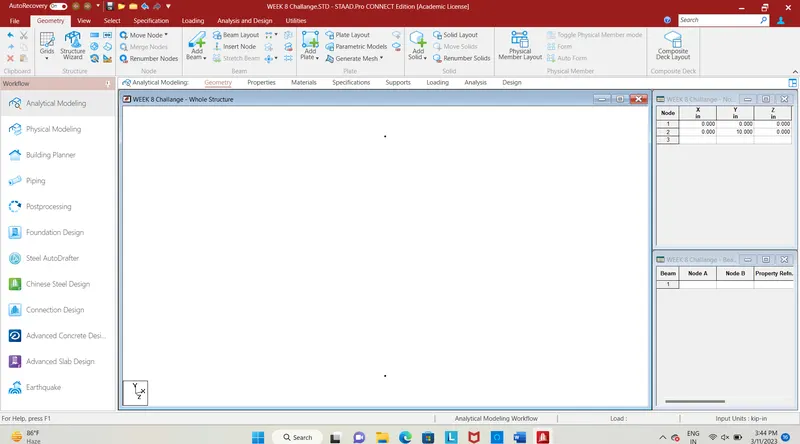
Fig. 1
- The first step is to enter the coordinates for node, enter the coordinates as (0,0,0) and (0,10,0).
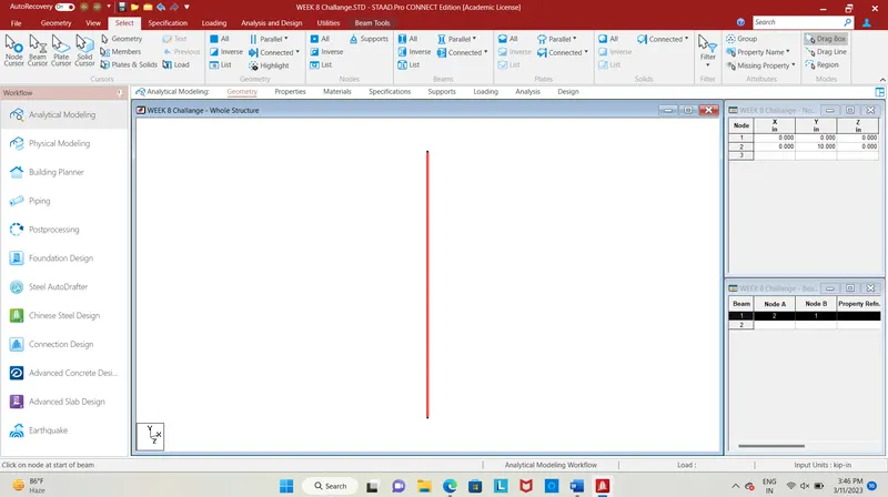
Fig. 2
- The pier has been created for a height of 10m, next step is to form the span and carriageway for the bridge.
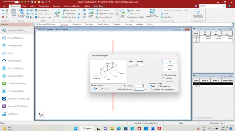
Fig. 3
- Select the pier and use translational repeat command in x-direction at a spacing of 12m and steps as 1, another pier will be created to represent the span of the bridge.
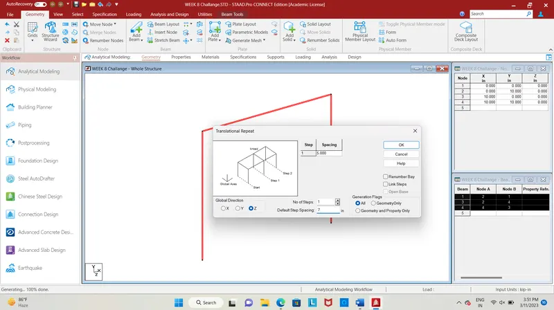
Fig. 4
- Select the two piers and use translational repeat command in the z-direction, at a spacing of 7m another two piers will be created to form the width of the bridge.
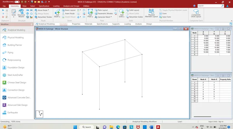
Fig. 5
- The bridge of 12m span with a carriageway width of 7m has been designed.
- Next step is to assign the properties for the structural members of the bridge.
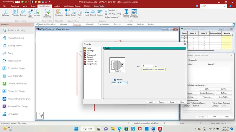
Fig. 6
- Add a circular section of dia 1m by selecting piers and using prismatic tab in specification bar and assign it.
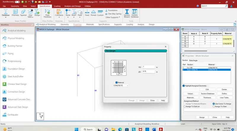
Fig. 7
- The next step is to assign the property for the cross beam and longitudinal beams, add a rectangular section of 1m * 0.75m, select the beams and assign the property to the beam.
- Now creating deck slab.
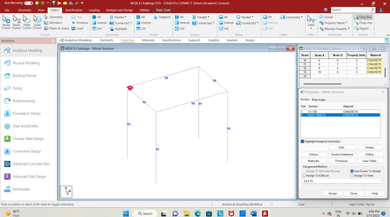
Fig. 8
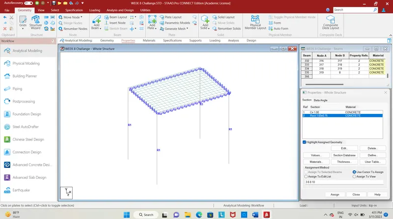
Fig. 9
- Add a node in x and z-direction by using repeat command with a spacing of 0.5m, connect the nodes and add a plate by using add plate command, copy the plates in x-direction and z-direction to form the deck slab for the bridge.
- In x-direction repeat the plate for 23 steps and in z-direction for 13 steps at spacing 0.5m each, thus the deck slab has been created.
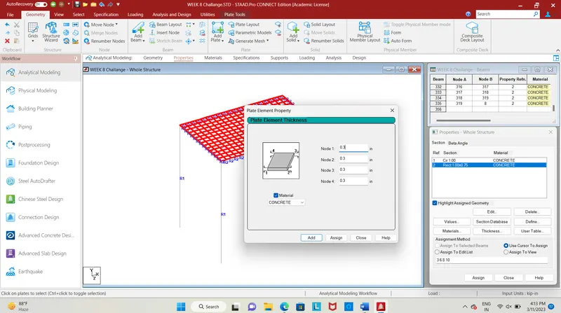
Fig. 10
- Add plate thickness of 0.3m for the deck slab, select all the plates of deck and assign the the property by clicking assign to selected beam.

Fig. 11
- The plate thickness has assigned, the structural members are given with required properties.
- Next step is to assign the support to the bridge structure.
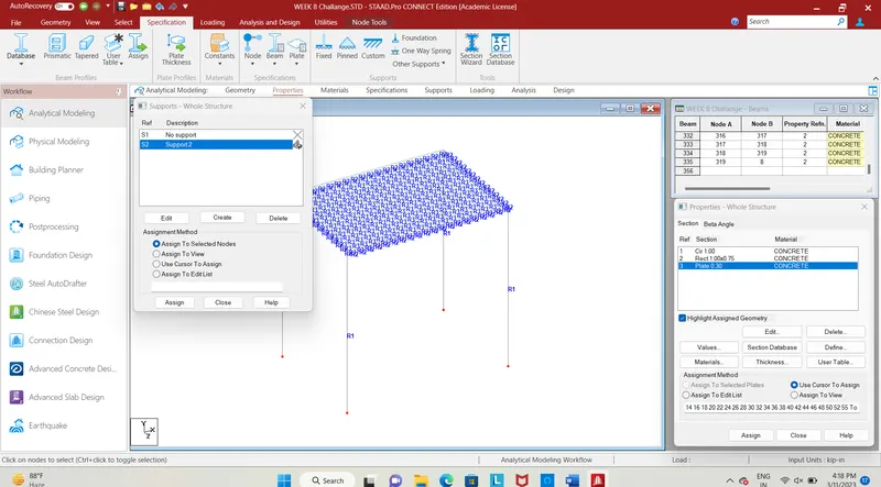
Fig. 12
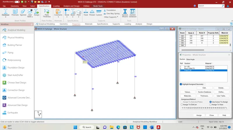
Fig. 13
- click on the specification, select fixed support, after the select the bottom nodes of the pier and then click on assign to selected nodes, the fixed support will be assigned to piers.
- Now we apply loading to the structure.
- We apply 1033.46KN of load as vehicular load.
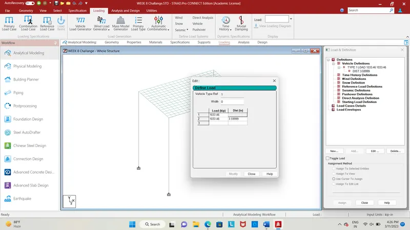
Fig. 14
- Next step is to give loading to the structure, click on vehicular definitions, define the load enter the calculated value of load as 1033.46 and distance as 3.6m click add.
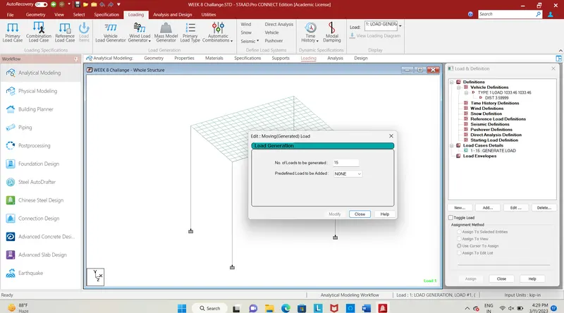
Fig. 15
- No. of loads to be generated= span length + length of vehicle= 12+3= 15
- In the load case details add, add load generation to be 15.
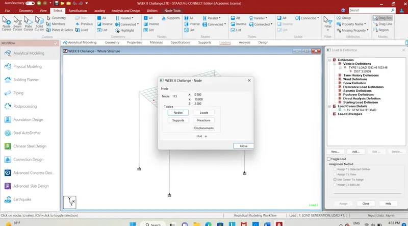
Fig. 16
- By clicking on random node and using this coordinate to apply the load.
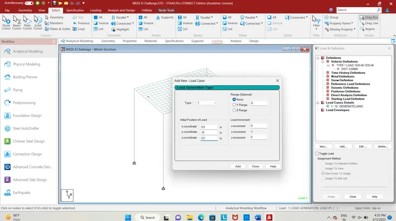
Fig. 17
- We use (0.5,10,2.5) coordinate to apply the load and the load increment value as 1 in x direct then click add.
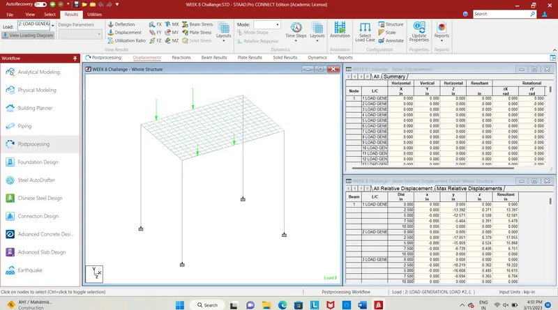
Fig. 18
- The fig. shows the loading diagram of centrifugal load acting as vehicular load.
- Load is applied, now we go for analysis and design.
RESULT :
To analyse the structural behaviour of members for the designed bridge for the applied centrifugal load.
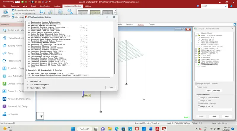
Fig. 19
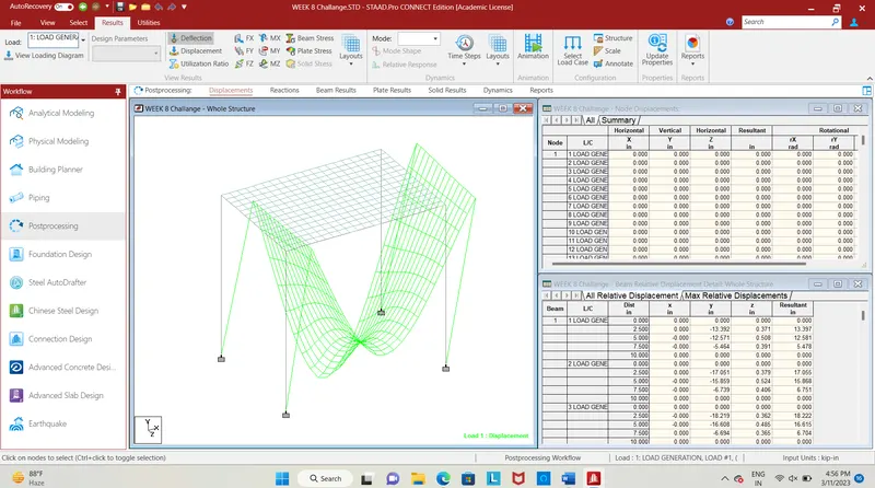
Fig. 20
- The fig. shows the deflection pattern of the structure due to centrifugal load.
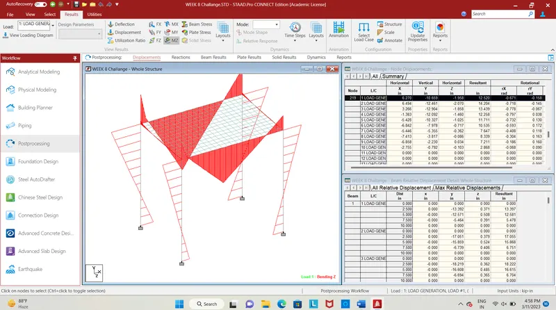
Fig. 21
- The fig shows the bending moment along z direction, click on Mz in the post processing tools tab.
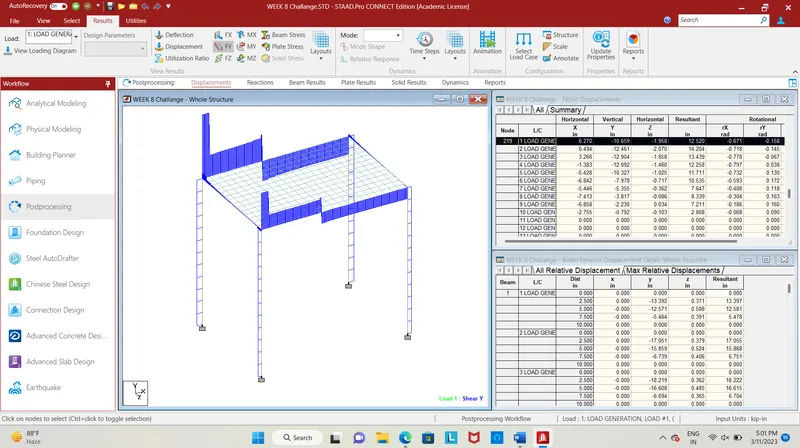
Fig. 22
- The shear force along y direction is shown, click on Fy in post processing tools tab to show the shear force for applied load.
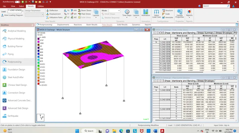
Fig. 23
- Clicking on plate stress in post processing tools tab, stress diagram will be shown in contour image, which gives the maximum value as 22.63E^3 and minimum value as -4435 of My.
- Thus the centrifugal load has calculated using formula and the calculated load is applied on bridge using staad pro.