Week 8 Challenge
Week- 8
Q.1 Applying Load Exercise
For the structure modelled in previous exercise. Apply following loads
Form a Load case as DL for Dead Load
- Apply Self weight
- Apply member load of 3 kN/m on the rafter
- Apply member load of 6 kN/m on the secondary beams
- Apply point load of 20 kN at node intersecting inclined member on the top chord.
Form a Load case as LL for Live Load
- Apply member load of 4 kN/m on the rafter
- Apply member load of 7.5 kN/m on the secondary beams
Form load combination 1.5DL+1.5LL
Procedure: -
- Form a Load case as DL for Dead Load
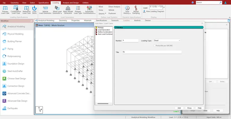
Step 1: - Loading – Load Case details - Add – Loading Type – Dead Load - Add
Apply Self Weight: -
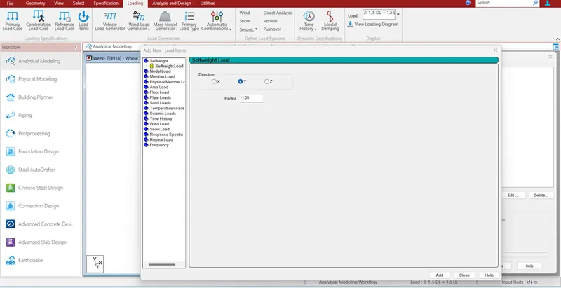
- Modeling – Loading – DL – Add – Direction – Y Factor -1.05 – Add
- 5% Extra considered in self-weight for the connections and bolts etc.
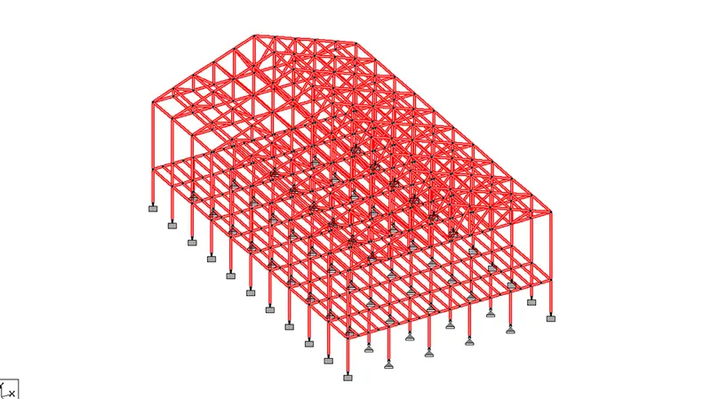
- Next assign the DL- select assign to view and click assign
Apply Member Load for 3 Kn/m on rafter.
- Now, similarly under Dead Load case add 3Kn/m Member Load on Rafter
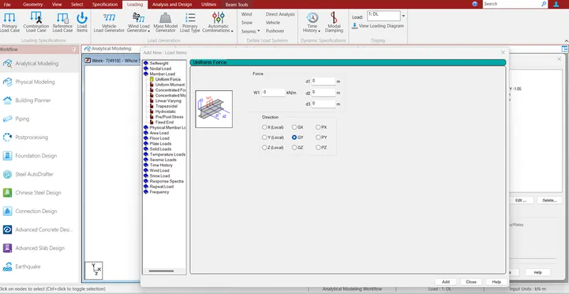
- Loading – Dead Load – Add – Member Load – Uniform Force - W1 -3 Kn/m, Direction GY – add – Now select the Rafter by group tool – Assign to selected member.
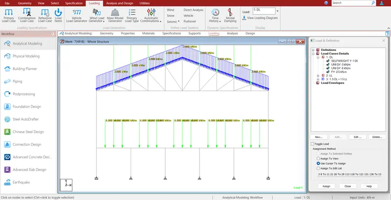
Apply member load of 6 kN/m on the secondary beams
- Similarly apply member load on secondary beams
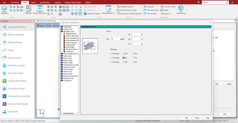
- Loading – Dead Load – Add – Member Load – Uniform Force - W1 -6 Kn/m, Direction GY – add – Now select the Secondary beam by group tool – Assign to selected member.
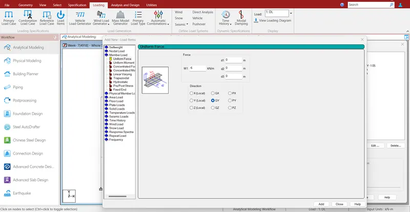
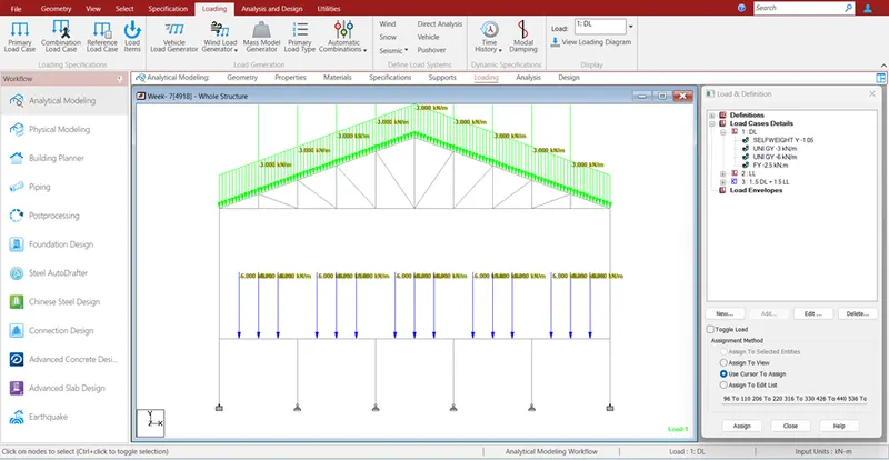
Apply point load of 20 kN at node intersecting inclined member on the top chord.
- On the inclined member 8 intersecting nodes are present, So 20 KN is divided by 8 Nodes.
- 20/8 = 2.5 kN
- Loading – Dead Load – Add – Nodal Load – Node - Fy -2.5 Kn,– add – Now select the Inclined member Nodes by using node courser – Assign to selected member.
- With this all Dead load generated.
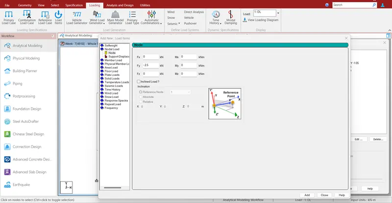
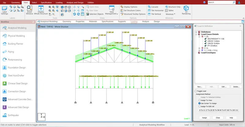
Form a Load case as LL for Live Load
- Go to Loading – Load Case Details – Add – Loading Type Live – Title Live Load – Add
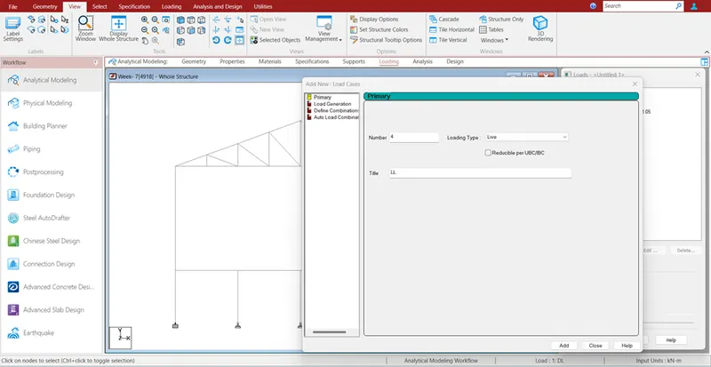
Apply member load of 4 kN/m on the rafter
- Now similarly we have to create Live Load by following same procedure.
- Loading – Live Load – Add – Member Load – uniform force – W1 -4 Kn/m – add – Now select the Rafter by using group option – Assign to selected member.
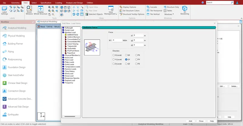
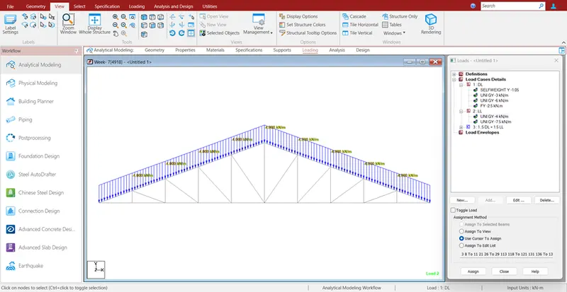
Apply member load of 7.5 kN/m on the secondary beams
- Follow Same procedure
- Loading – Live Load – Add – Member Load – uniform force – W1 -7.5 Kn/m – add – Now select the Secondary Beam by using group option – Assign to selected member
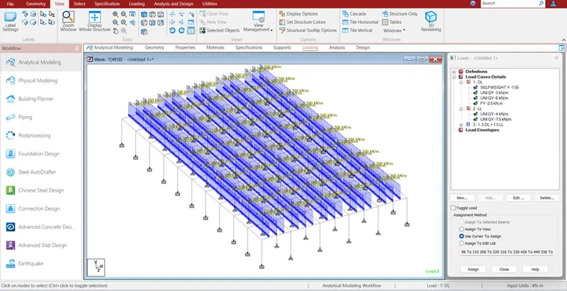
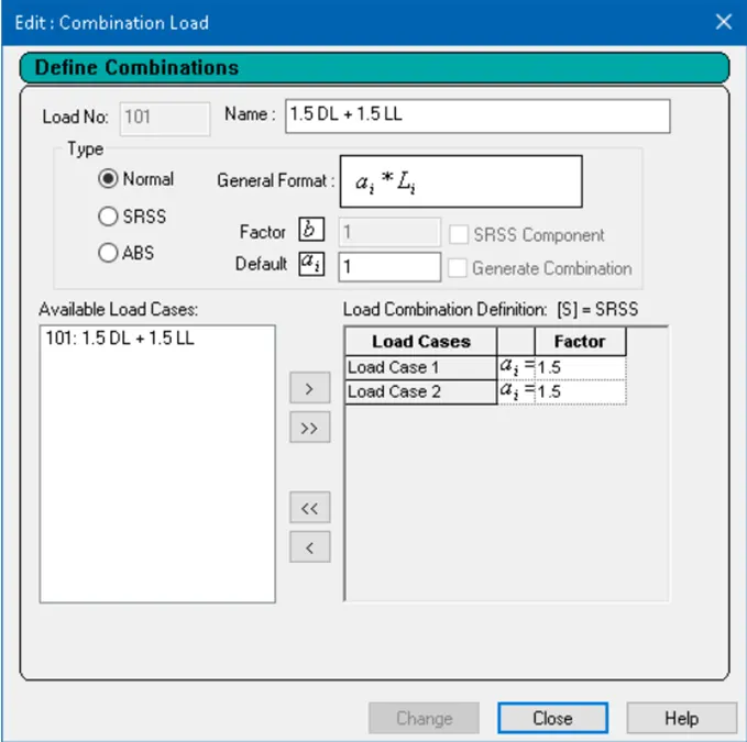
Form load combination 1.5DL+1.5LL
- Go to Loading – Load Case Details – Add – Define Combinations – Name and Factor 1.5 – Add
- Find Maximum Force and Minimum Force for member and present the STAAD result.
Continue previous challenge, Run the analysis and find following results on the member mentioned
- Run the analysis
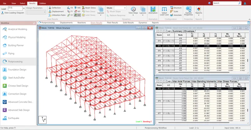
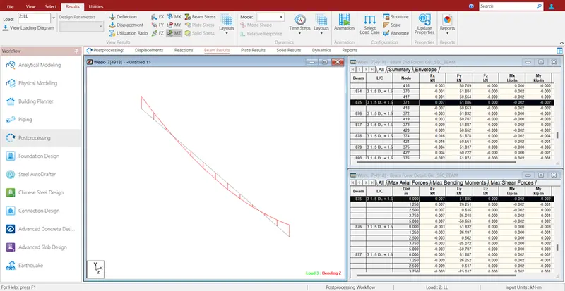
- Find the Maximum Moment in the Secondary beam for 1.5DL+1.5LL case
- Find the Maximum Axial force on the inclined bracing and identify the member having the maximum force for 1.5DL+1.5LL case
- Identify Bottom chord of Truss having Maximum shear Force & Maximum moment for 1.5DL+1.5LL case and present the values.
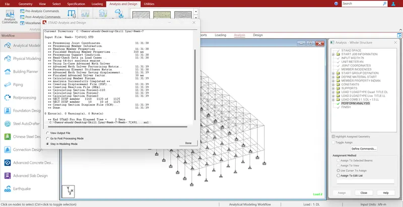
Run the Analysis
- Go to Menu bar – Analysis and Design – Run Analysis.
Find the Maximum Moment in the Secondary beam for 1.5DL+1.5LL case
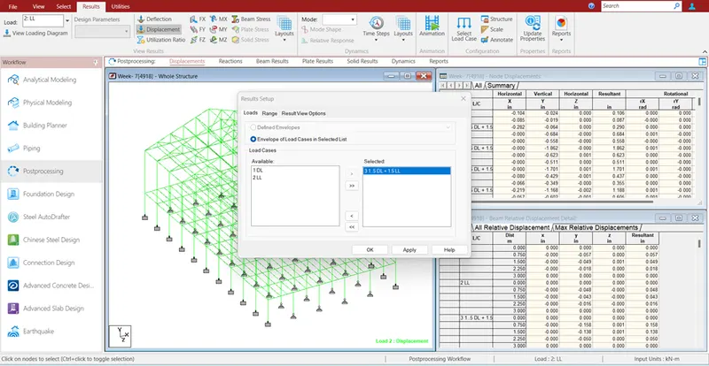
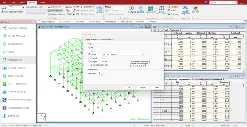
- Go to Post Processing – Results – Select Load Case – Load Case – 1.5 DL+ 1.5 LL – Range Tab – Group – Secondary Beams – OK.
Find the Maximum Axial force on the inclined bracing and identify the member having the maximum force for 1.5DL+1.5LL case
- Post Processing – Results – Select Load Case – 1.5DL+1.5LL – Range Tab – Group – Top Chord – Ok.
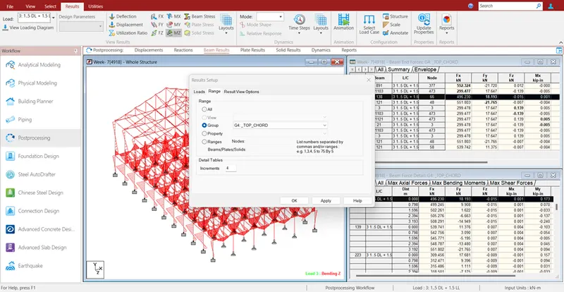
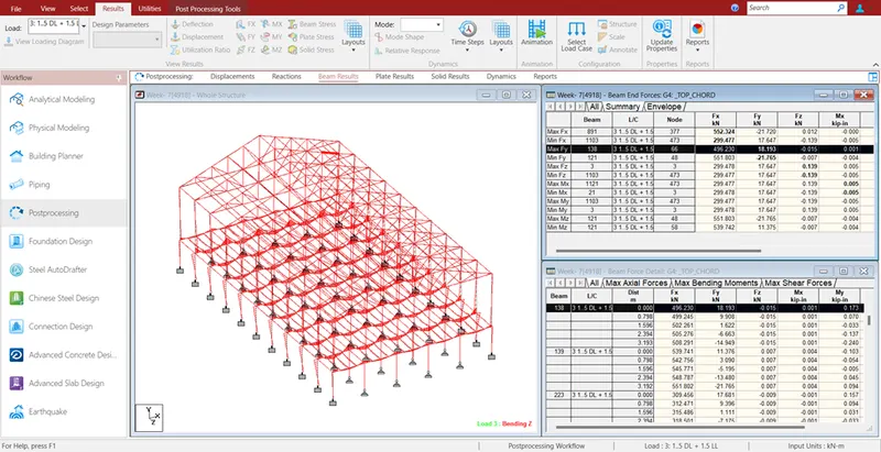
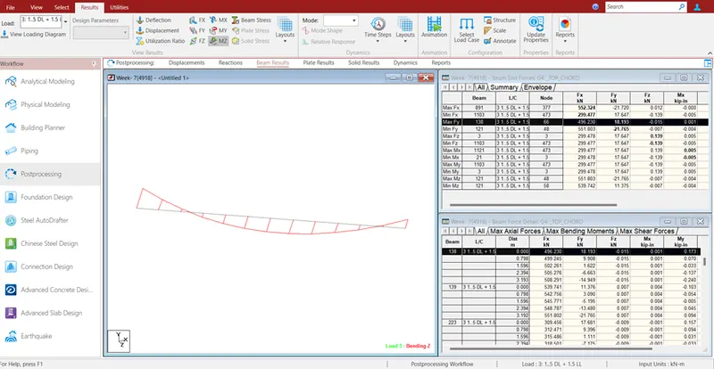
Identify Bottom chord of Truss having Maximum shear Force & Maximum moment for 1.5DL+1.5LL case and present the values.
- Post Processing – Results – Select Load Case – 1.5DL+1.5LL – Range Tab – Group – Bottom Chord – Ok.
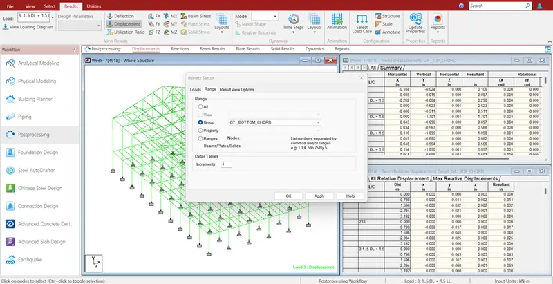
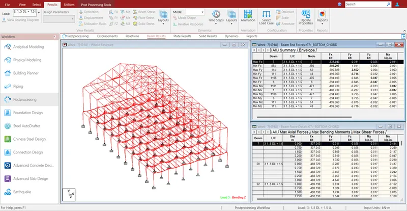
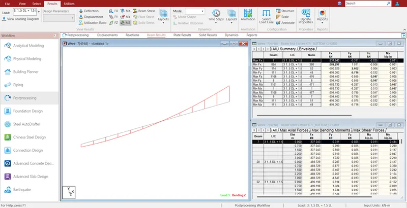
- View and Rectify the Warning, instabilities in the structure
- For the attached STAAD file identify the Warnings and fix the same and run the analysis.
- For the attached STAAD file identify the Warnings and fix the same and run the analysis.
- Go to Utility – Analysis Output – Warnings
The warning zero stiffness is due to the inclined member connecting to bracing middle are assigned as a truss member
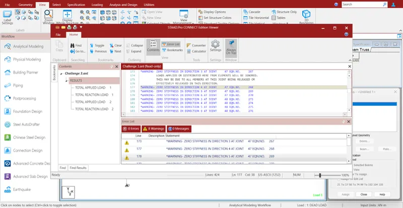
- To avoid this warning, the truss member specification to be removed for the bottom inclined member as shown below.
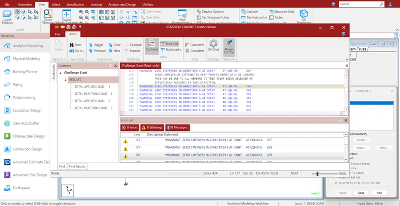
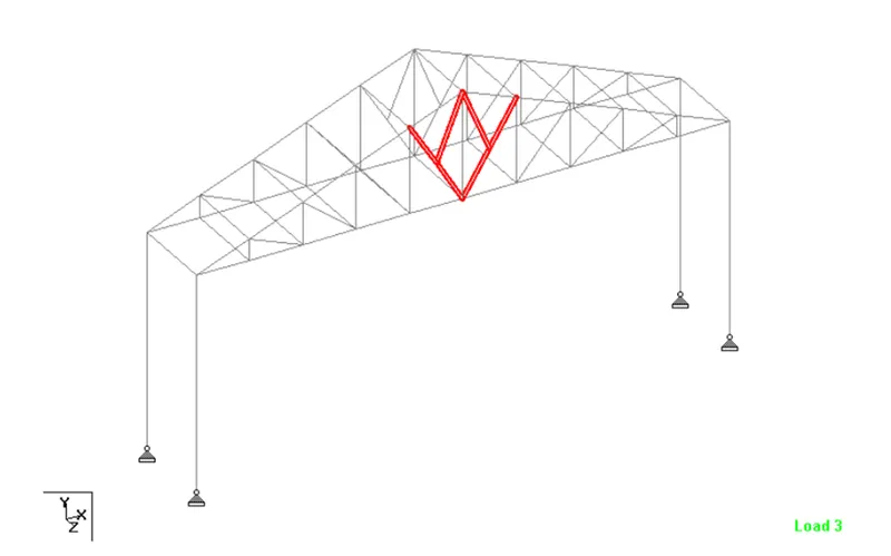
- From this type of assigning, the bottom inclined member will be made to take up the moments.
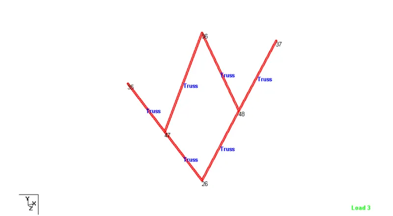
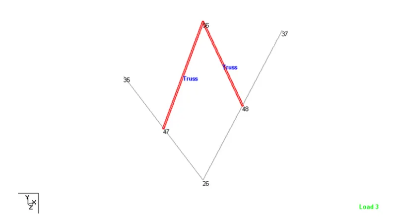
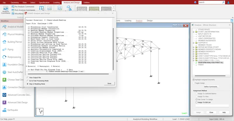
Result:- Given model analyzed and all warnings rectified.
- Design Parameter exercise
In continuation to challenge 1, Apply Design parameter for structure modelled for code IS800:2007.
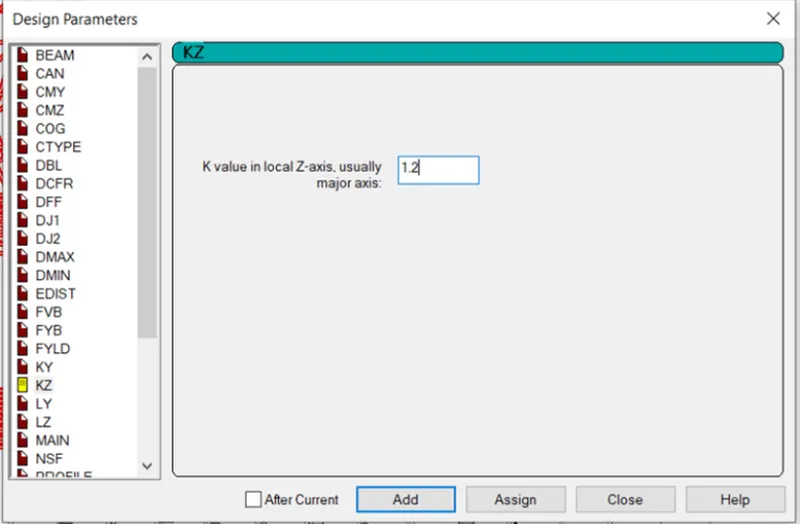
- Effective Length Lx, Ly, Lz for beams, Truss elements
- Effective length factors Ky, Kz for Columns
- Apply other design parameters for respective members
Procedure: -
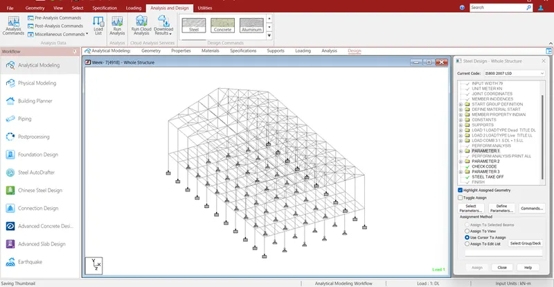
- Go to analysis and design tab
- Now go to Design Steel
- Select the IS Code 800 2007
- Now define the parameters for ly, lz for beams an truss ky,kz for columns
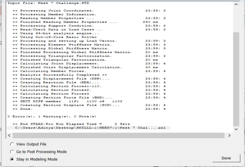
- Run the analysis to check errors and warnings.
Result: - All parameters has been applied successfully.