Week 8 Challenge
Load the UC parameter file. Complete the Ultracapacitor model. Set simulation stop time to 598 sec.
The model output should give, current, SOC, and Voltage as output
Ultracapacitor:-
An Ultracapacitor also known as a supercapacitor or electrochemical capacitor is a device for storing electrical energy which is growing rapidly in popularity The design and mechanism of operation are somewhat between an ordinary capacitor and a battery which opens up some interesting and valuable applications.
Like a battery a single ultracapacitor cell consists of a positive and negative electrode separated by an electrolyte However ultracapacitor store energy electrostatically like e regular capacitor not chemically like a battery there is a dielectric separator dividing the electrolyte also like a capacitor
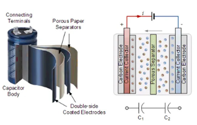
The small separation between electrodes permitted by this structure leads to much higher energy density than a normal capacitor whilst ultracapacitor stores less energy than an equivalently sized battery it can release it much quicker as the discharge is not dependent on a chemical reaction taking place
Because no physical or chemical changes occur when a charge is stored ultracapacitors can also be used many times over without degradation
Applications for Ultracapacitors:
The performance benefits of ultracapacitors come into play most effectively when a large spike in power consumption, or a large-scale, repeated charging cycle is required.
- Electric or hybrid vehicles - to provide a quick burst of acceleration over short distances, or to start the main motor.
- Quick-charging electronic devices
- Waterproof/weatherproof energy storage (e.g. remote wind farms)
- Military vehicles (starter engines for tanks, submarines, compact power for missiles)
STEPS TO CONSTRUCT UC MODEL:-
Their equation in the UC model is defined first which gives us SOC Current and OCS
These are the 3 parameters that influence UC
OCV Defines the SOC of Ultracapacitor
Max Voltage or voltage is directly proportional to the charge stored in the battery
The amount of the charge is directly proportional to the current that can flow in the circuit.

Where:
eta is the Coulomb efficiency.
Q is the electric quantity or charge on UC.
I is the current.
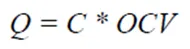
Q depends on capacitance which is the charge storage capacity measured in Farads.
The OCV is a measure of the electric field between plates.
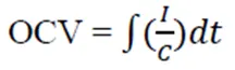
Capacitance and OCV give 'Q'
The integration of current over 'C' gives 'OCV'.
In the UC model calculations for current and SoC are done as said below:
Firstly the current consumed is calculated which is fed into an SoC calculation block.
The SoC is then calculated based on the amount of current drawn and pushed back into the UC.
Hence formula for current is given as:

Where:
R is the lumped resistance
Vmax is the max. voltage
eta is the efficiency during the charge-discharge cycle.
PUC is the power demand which is to be supplied by UC and it is the first input in this model which basically comes from Energy management systems.
Here we will see how to construct the ultracapacitor model and to obtain current, SOC and voltage characteristics as output results.
Step 1 : Simulink Model
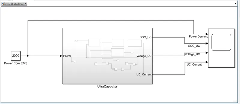
Open the Simulink blank model and let's start building the ultracapacitor model. The ultracapacitor model is shown below. The power is taken as the input for the ultracapacitor. The ultracapacitor subsystem consists of current calculation, open circuit voltage calculation, SOC estimation and charge calculation.
Step 2: UC SOC
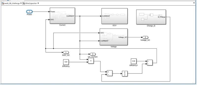
The ultracapacitor subsystem block is shown below. The highlighted part shows the state of charge (SOC) calculation. The SOC is calculated using the following formula.
SOC = (UC current*UC efficiency)/charge dt
Where efficiency is the Coulomb efficiency of the ultracapacitor, Q is the electric quantity and I is the current from the ultracapacitor.
Step 3: UC Current
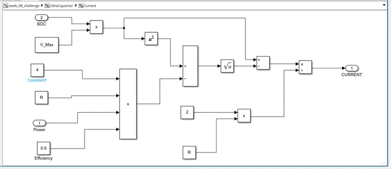
The current calculation is shown below. The current equation is considered as a function of SOC, lumped resistance of the system mainly consisting of the internal resistance of UC and connecting cables. The current equation is given below. The ultracapacitor current is calculated as-
UC Current= ((SOC*V_max)-sqrt((SOC*V_max)^2-4*R*puc*eff)2*R))
Where R is the lumped resistance, Vmax is the maximum voltage of the UC and η is the efficiency during the charge/discharge cycle.
Step 4: Open Circuit Voltage
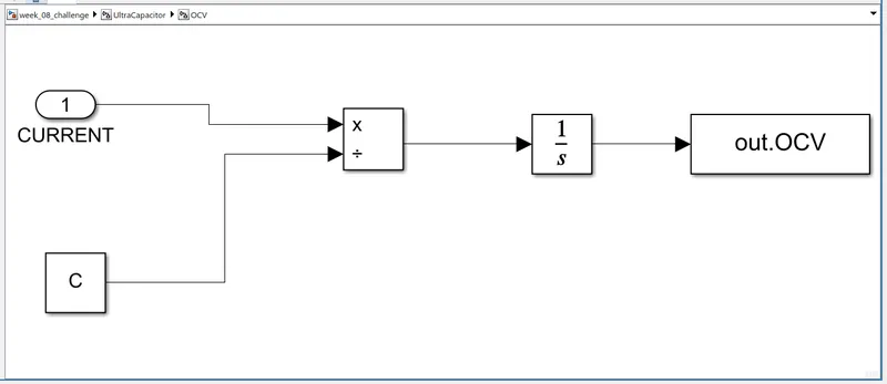
The Open Circuit Voltage (OCV) calculation is shown below. The OCV formula is as follows,
OCV = int(1/C)dt
Step 5: UC Charge
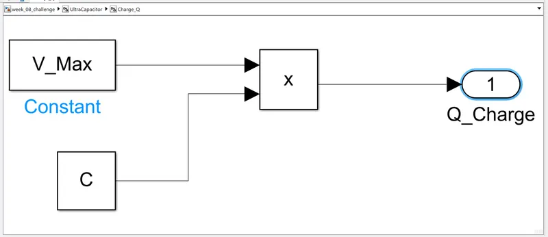
The charge_Q subsystem is shown below. The charge is determined by the product of maximum voltage and capacitance. The charge formula is as follows,
Charge = V_max*C
Step 6: UC Voltage
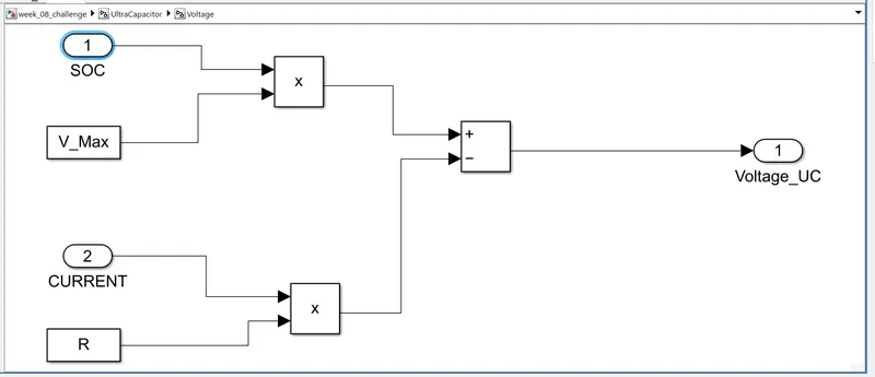
The voltage block subsystem is shown below. The voltage formula is as follows,
Voltage = (SOC*V_max) - (I*R)
The resistance, capacitance, and the maximum voltage value is given below. Type these values in the Matlab command window.
R=0.10;
C=83;
V_Max=750;

Result:
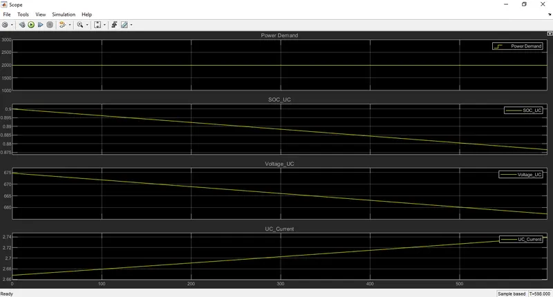
The figure below shows the result for ultracapacitor SOC, ultracapacitor voltage, and ultracapacitor current. The simulation stop time is 598 seconds.