Week-4 Challenge WOT Condition Part-2
Introduction
The powertrain block set provides fully assembled reference application models of automotive powertrains, including gasoline diesel, hybrid, and electric systems. it includes a components library for simulating engine subsystems, transmission assemblies, traction motors, battery packs, and controller models. The powertrain block set also includes a dynamometer model for virtual testing. MDF file support provides a standards-based interface to calibration tools for data import.
The powertrain block set provides a standard model architecture that can be reused throughout the development process you can use it for design tradeoff analysis and component sizing control parameter optimization and hardware-in-the-loop testing you can customize models of parameterizing components in a reference application with your own data or replacing a subsystem with your own mode.
1. What is the difference between mapped and dynamic model of engine, motor and generator? How can you change the model type?
Mapped model: The mapped model is a type of model in which the data is loaded through a lookup table. The output values are stored for the corresponding input values for the engine, Motor, and generator. These simulations do not run on real-time data, hence the accuracy of these models is not very high. The time required for the completion of these simulations is very low as not many of the high calculations are involved. This model can be used for design trade-off analysis, sizing of the components, control parameters optimization, and hardware in the loop testing you can customize the model using the reference example and customize the model according to your own data.
i. Mapped motor: This model is mostly used when the user needs the results quickly, and the user doesn't have information about the motor parameters.The mapped motor used in the torque control mode. The output torque and the reference torque are compared and the changes are mode.
ii. Mapped engine: This model is based on lockup table data. This setting is the default setting in the Powertrain block set. These models are less accurate and the lookup table data are based on the brake torque, commanded torque, and engine speed.
iii. Mapped Generator: This is also the same as the other block sets. Most of the data is taken from the input tables and they required less time and are less accurate.
Dynamic models: Dynamic models are the model that used data from various subsystems to generate the output. It runs in the real-time simulation where the required input is taken from the drive cycle and the simulation is run. The accuracy of the system is very high as the data is taken for the real-time simulation, but the time taken for the simulation to run is very high.
i. Dynamic motor: in this model the three-phase interior permanent magnets synchronous motor is used. This model uses a three phase input to regulate the single phase current allowing the control of torque and speed. This model is used when the user knows all parameters of the motor for the simulation.
ii. Dynamic engine: This type of model used the real-time data fed by the user during the run time of simulations. This model is more accurate than the mapped engine model and is mostly used when the subsystem data is required.
iii. Dynamic generator: The dynamic generator block involves the user entering the parameter manually during the run time of the simulations for their particular applications.
To change the model from mapped to dynamic
To change the model in simulink we first need to open the HEV model in the simulink.Then double click on the passenger block
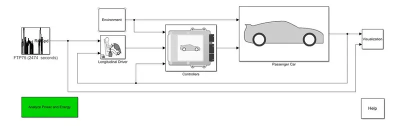
Open the Electric plant block
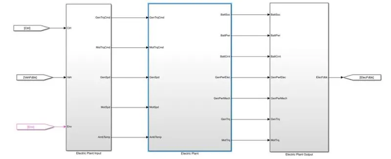
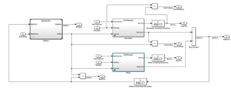
Inside that, will find the motor and generator block. Double-click on any block to open the mapped and dynamic model.
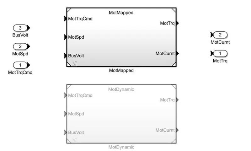
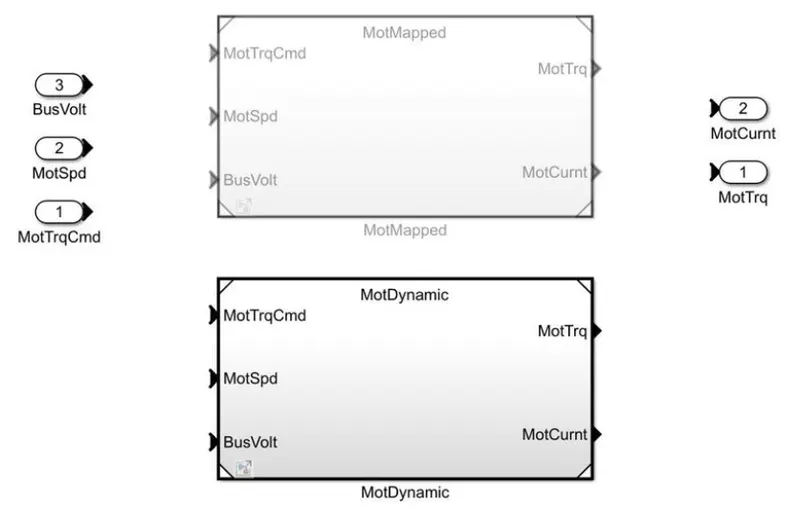
2. How does the model calculate miles per gallon? Which factors are considered to model fuel flow?
To Calculate the fuel efficiency first, the automobile is filled with a fuel tank capacity the distance in the odometer is noted and the vehicle is derived to the full tank capacity fill the tank is empty.
once the tank is empty the distance in the odometer is recorded and the difference in the reading is calculated, this is the total distance traveled in the full tank capacity of the vehicle.
Then the distance is divided by the capacity of the tank and the average millage of the vehicle is calculated.
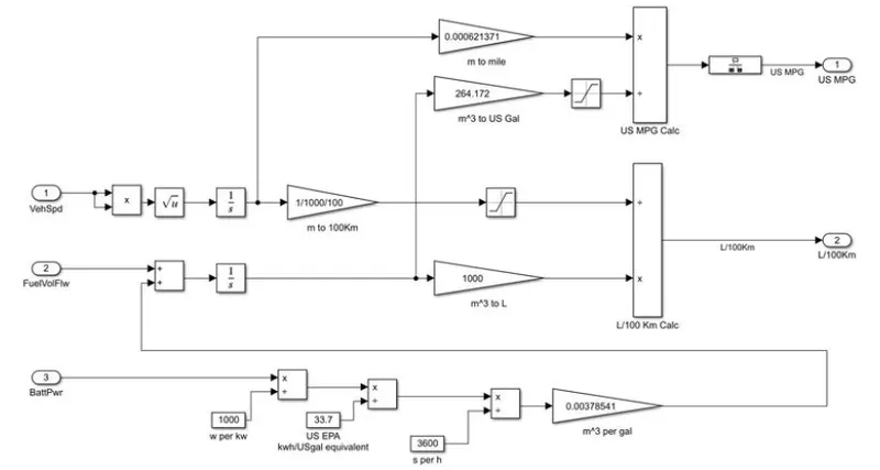
In the above model, we can observe that factors that are needed as input to the model are vehicle speed fuel volume flow and battery power. As value changes the performance of the vehicle also changes.
Here first the velocity is converted into the distance by integrating the velocity values and then the distance is converted from meter to miles and KM.
Then similarly battery power is converted to volume by multiplying and dividing by the constant conversion value. Then the battery and fuel volume flow are added and integrated to get the total volume of fuel consumed. Now, this volume is converted from cubic meters to gallons and liters.
Now the distance and volume of the fuel are divided to get performance results in miles per gallon.
Factors consider modeling fuel flow.
Weight: The weight of the vehicle is considered as it plays an important role in determining the amount of fuel consumed as the weight increases the tractive efforts required to overcome the vehicle rest inertia will increase.
Drive cycle: At a certain speed engine is able to operate at RPM which provides maximum efficiency, driving at an irregular pace or at a higher speed makes the engine provides lower efficiency. Aggressive accelerating and braking drive cycles decrease the fuel economy of the drivetrain.
Resistance: if the vehicle is subjected to high opposing wind speed road grade then there is a higher force acting on a body in particular aerodynamic drag and hill climbing force. this force increases the power needed to overcome the tractive effort in turn making the engine. consume more fuel.
3.Run the HEV ReferenceApplication with WOT drive cycle. Change the grade and wind velocity in the environment block. Comment on the results.
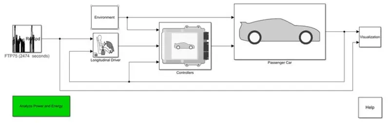
We change the drive cycle to WOT and set parameters as
Nominal velocity-60mps
time to start deceleration- 40sec
saturation time - 100 seconds
wind velocity - 10m/s
Grade - 5
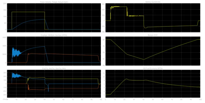
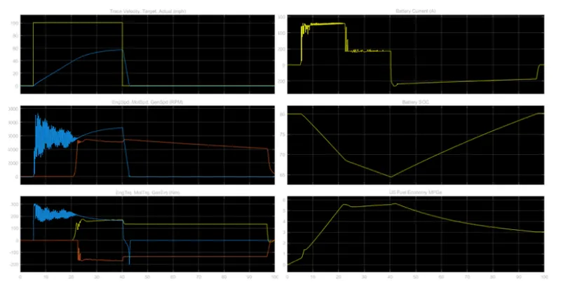
Trace and actual velocity: we see here that trace velocity is given as input and actual velocity is the output, top velocity achieved = 74mph, time taken to attempt maximum acceleration = 40.30sec, and time taken to decelerate = 4.242 sec
Engine, motor, generator torque: The maximum engine speed recorded is 54577.57RPM, maximum motor speed = 9571RPM, we see whenever the SOC falls below 70% the engine gets activated by providing torque as well as charging the battery.
Engine, motor generator torque: The maximum torque of the engine = 163.3NM
maximum torque of motor = 287.8NM
Battery current: the maximum current provided by the battery is around 570amps and after reaching a certain point the value is constant and is the maximum amp limit of the battery. As soon as the engine and generator get started the battery current drops as the load are shared by the engine and the current goes negative because of the occurrence of regenerative braking
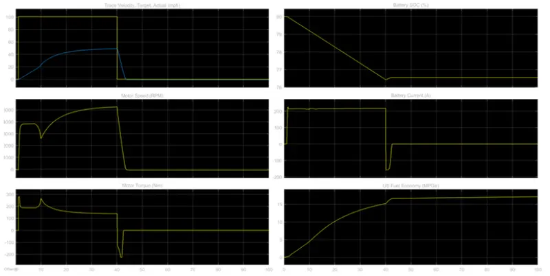
4. Keeping all other parameters same, compare the simulated results of hybrid and pure electric powertrains.
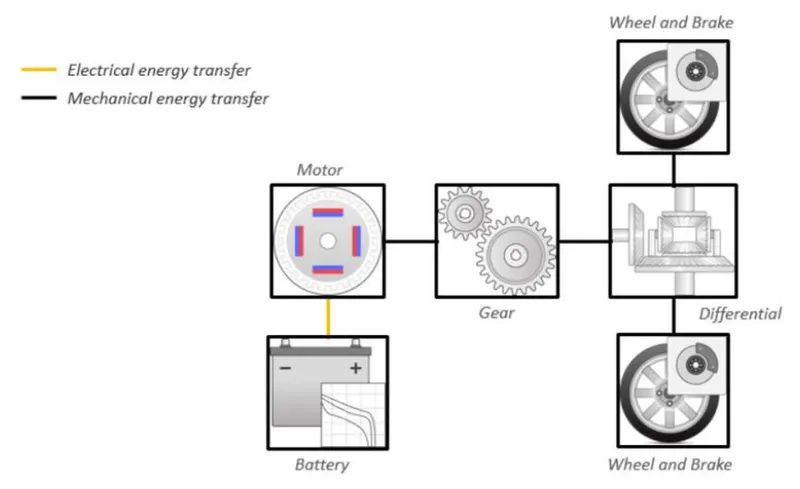
Fully Electrical Vehicle
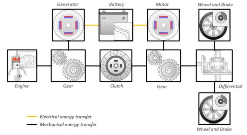
HEV
EV
HEV