Week 8 - Challenge 6 - Core & Cavity Design
AIM: Create the Core and cavity blocks for the switch bezel designed in the earlier challenge.
Introduction:
The plastic parts were usually manufactured with the forming process, particularly the Injection molding process. In the forming processes, the part is formed between two or more dies based on the geometry of the part. In forming processes vacant space is left between the dies which are the same as the geometry of the part then the space is filled with the molten material on which the part is intended to manufacture. In the injection molding process basic die consists of a core and cavity. When the molten plastic is injected into the space between the core and the cavity the injected plastic gets frozen, and part is formed. The core will be the one-half of the die which has a projection in it and the cavity will have the hollow space on the cavity block.
The core and the cavity will move in the tooling direction. Generally, the core will be the moving part and the cavity will be the fixed half through which the molten plastic is injected into the mold. The core and the cavity will be separated by the parting surface.
Core and Cavity design for the switch Bezel Model:
C surface is formed either with the Class A surface or Class B surface it will be decided based on the draft of the Class C surface and the Parting surface. In this model as the Class C surface is visible from the A side surface along the tooling direction and the Parting surface must be kept on the B side surface as the Plastic defect ‘Flash’ might appear on the parting surface which will deteriorate the aesthetics of the product if it is kept on the Class A surface.
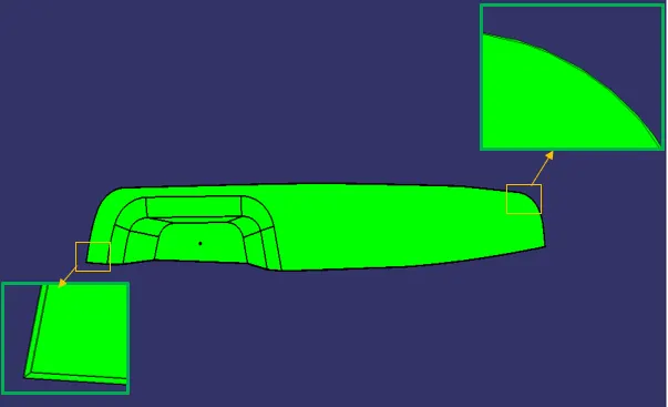
As we can see in the picture that the C surface is visible and has positive draft along tooling axis with Class A surface and the parting surface will fall on the B side surface. Therefore, the A and C surface will be formed by the core and the B surface is formed on the cavity side.
CORE DESIGN:
Parting surface of the core is created by trimming the Class A and Class C with Class B surface.
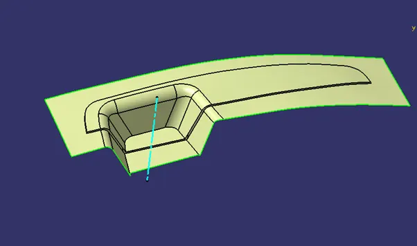 sni
sni
Then a block is created by extruding the rectangle along the tooling direction. As shown in the figure below.
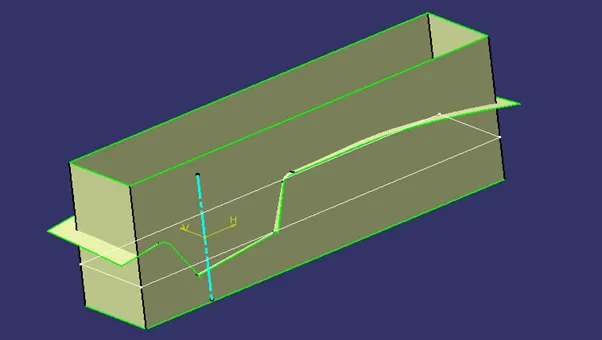
Then this rectangle is trimmed with the parting surface and the rectangular surface which is created.
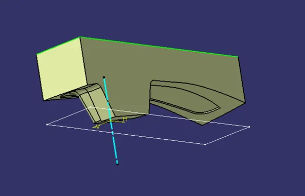
Then the top of the surface is closed by using Fill command and this shell is converted into a solid by using the ‘Closed Surface’ command in part module.
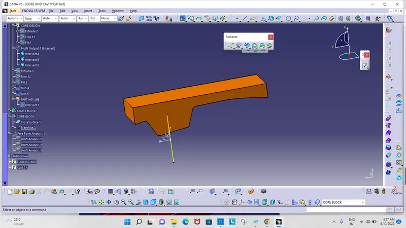
CAVITY DESIGN:
The parting surface of the cavity will be the B surface of the part.
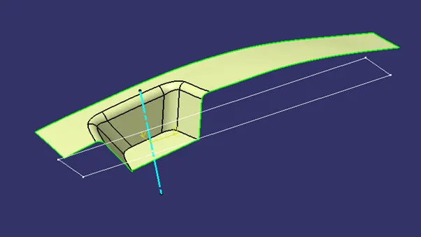
The complete entire block is created by extruding the rectangle and closing the bottom of the shell using the Fill command as said in the core design. Then the surface is changed into solid using the ‘Closed Surface’ command in Part design module.
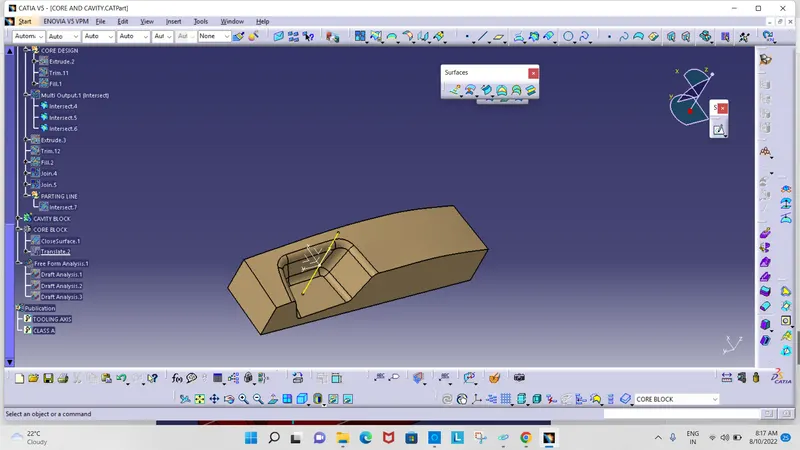
CORE AND CAVITY ASSEMBLY:
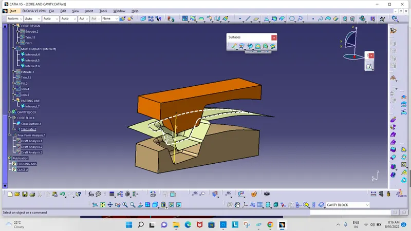
The core and the cavity were translated 50mm along the tooling direction for the better visualization