Week 8 - Challenge 6 - Core & Cavity Design
Aim:
This project aims to create a Core and Cavity for the Switch Bezel Component and perform the draft analysis for Switch Bezel.
CREATION OF TOOLING AXIS:-
- Considering the Ejection from the cavity of the mould after manufacturing the interior trim (switch bezel) must have the nominal 3-degree draft angle.
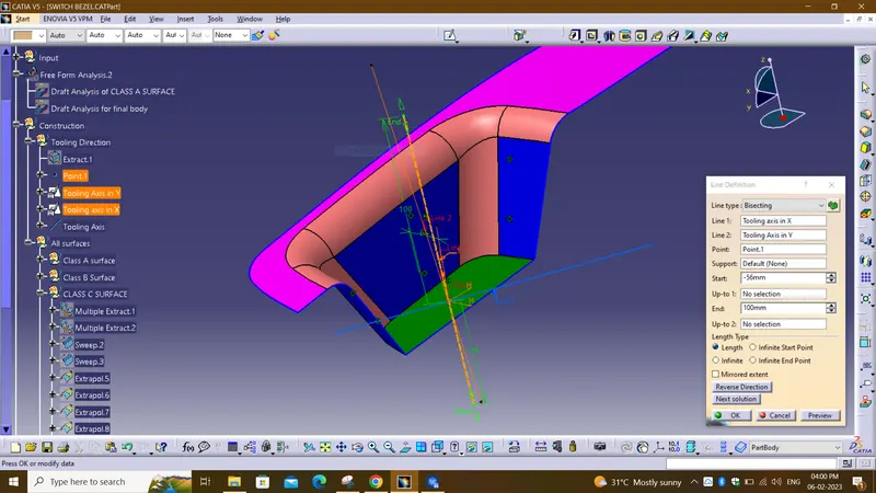
- Hence the tooling direction is created by considering the above factor and bisecting method is used.
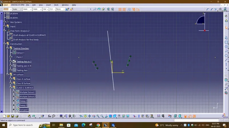
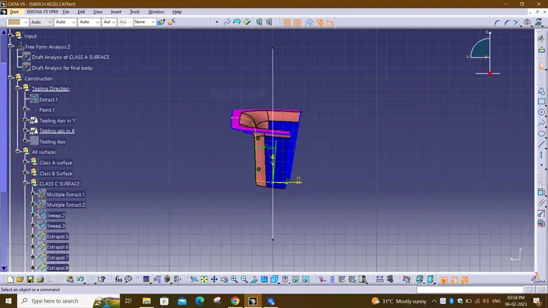
- The base surface of the class – A was extracted and a point at the centre is created and an axis system was inserted to the point with the current feature is disabled.
- Then, using project intersection along yz plane is created and the two inclined lines were drawn inside the positioned sketch.
- Then bisecting lines with the two inclined lines were drawn.
- Now the same procedure is done along the xz plane but on one side we don’t have inclined lines so the centre point is used to extrude a line along the z-direction and gave a measurement of 6 degrees (Tentatively).
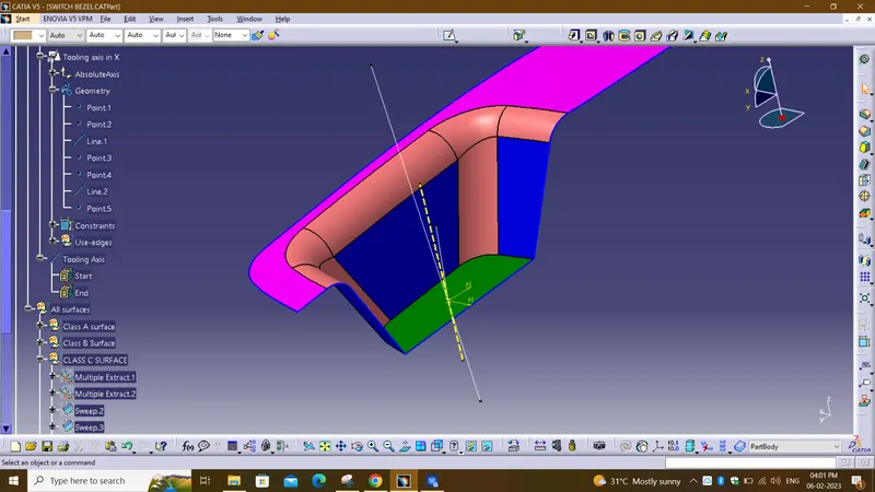
- With these two lines from sketches 1 and 2, the bisecting line is crated and published as Tooling Axis(tooling direction).
CLASS-A SURFACE:
The class-A surface is used in the automotive design industry. it describes the final production surface data for the aesthetic parts.
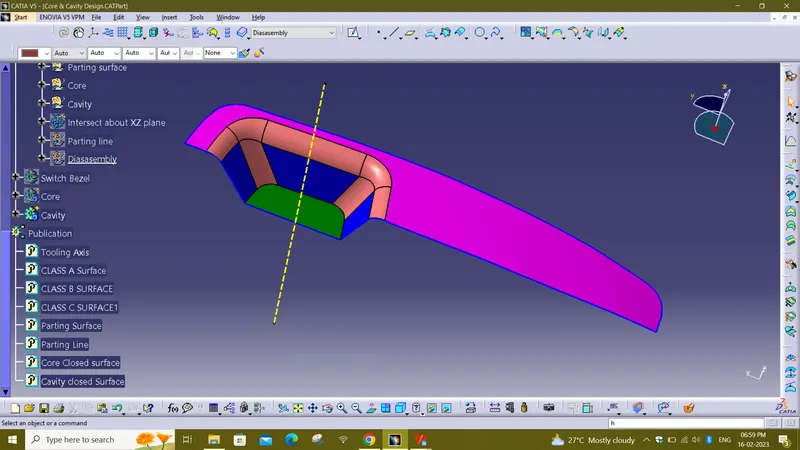
DRAFT ANALYSIS ON CLASS-A SURFACE:
- Go to insert> analysis> feature draft analysis
- Align the tooling axis with the compass.
- Click on the surface and see that the surface is within the permissible limit of the draft values.
- The surface should be green and in the column nominal value 3deg given as input. hence the draft analysis on the class-A surface is successfully performed.
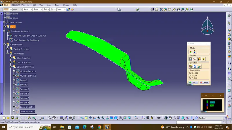
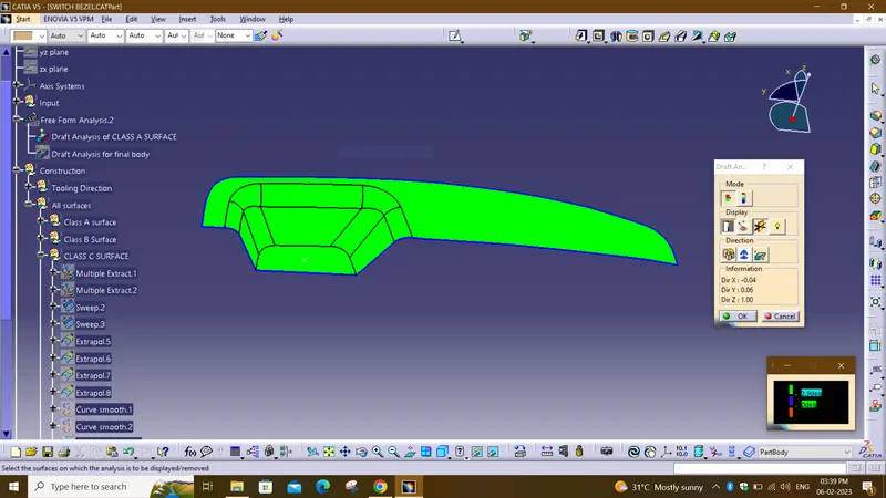
CREATION OF CLOSED SURFACE:-
- Now the class – A and Class- C surfaces were joined together by removing the gaps in-between them with the help of extrapolation(tangent continuity) and Trim surface.
- Then the exact surface of the Switch bezel was trimmed from the above-resulted trim surface with the class-B surface.
- Then, by defining the part body by using the Closed Surface command in Part Design, the component's solid body is created.
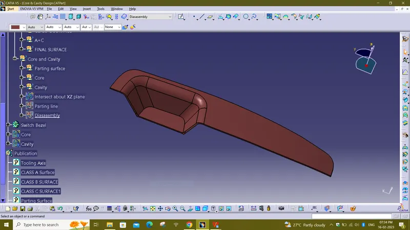
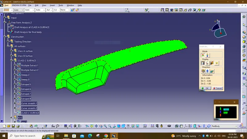
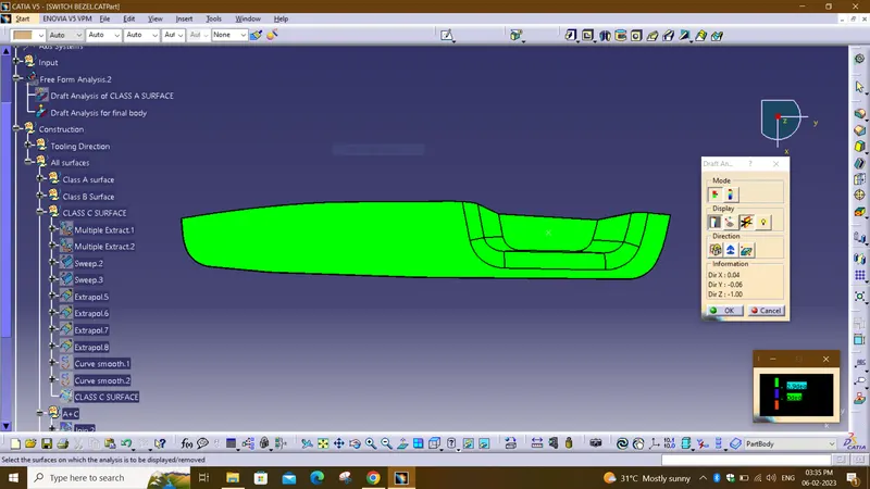
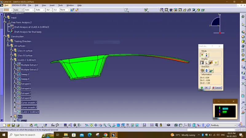
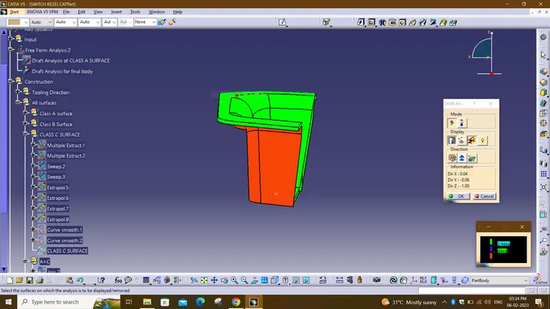
DRAFT ANALYSIS ON CLOSED SURFACE:
- First the class – A surface is checked before creating the Class –B&C surface and finally the solid body must be analysed. Both can be done by following the below procedures.
- By changing the view mode to custom view parameters – Material mode then the feature draft analysis is enabled.
- Then the compass was activated and placed with the tooling axis by dragging the red pointer and then locked it.
- Then, by selecting the quick analysis mode, the nominal value will be 3 degrees and checked for the component's draft angle.
- The green colour area shows that it satisfies the 3-degree draft angle. If not satisfied then by using the Running point tool the area is measured and then altered to get a successful draft for the created tooling direction.
CORE AND CAVITY design for switch bezel:
PARTING SURFACE
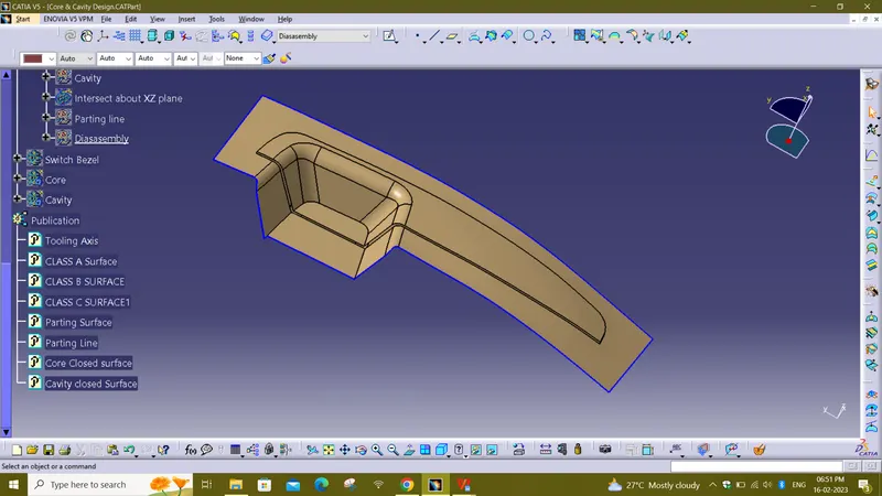
- Generally injection mold has two major components : the movable half and the fixed half, during the injecction molding process, these two halves are pressed tightly from a sealed hollow to avoid the melt flow leakage and maintain certain holding pressure, the pressed surface are called parting surface , usually parting surface are the biggest projection outline of the part.
PARTING LINE
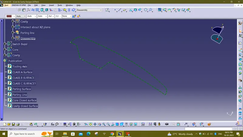
- A parting line is an inevitable part of injection molded products.
- It is the line of separation between where two halves of a mold meet.
- It manifests itself on injection molded parts as a line that runs the entire perimeter of the part.
- In most parts, it is just a line that runs straight down the middle.
Core & Cavity:
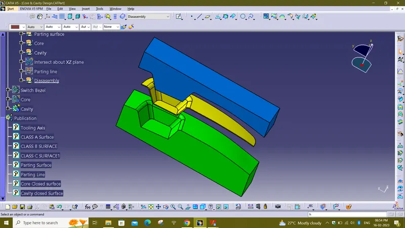
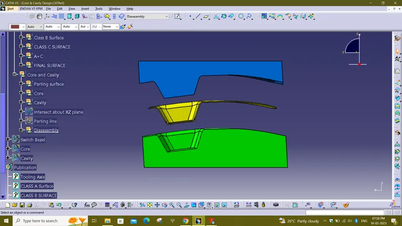
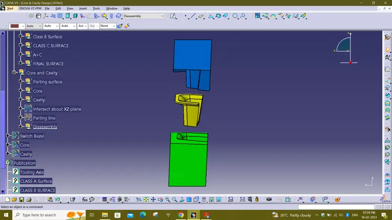
- The core & cavity are the shaped sections in either half of the mould tool which give the plastic product its final shape.
- The hot molten material is injected into the core & cavity and then sets hard into shape.
- The design of the core & cavity is essential in the correct formation of the product.
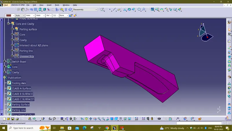
- Core is an extended or male portion of the mould which creates the internal plastic part surface
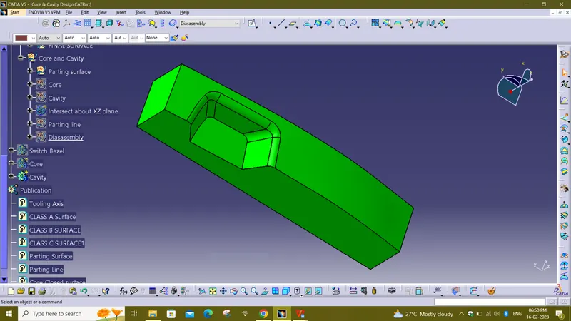
- Cavity is a depression or female portion of the mould which creates the external plastic part surface.
CORE BLOCK:
CAVITY BLOCK:
CORE AND CAVITY WITH PART:

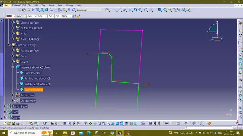
Intersection about XZ plane:
CONCLUSION:
- The Core and cavity blocks for the switch bezel component is created.