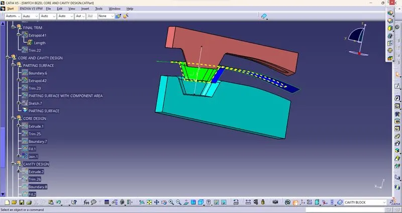
Week 8 - Challenge 6 - Core & Cavity Design
Darft analysis:
- Draft is a provide an angle to plastic component with cavity to reduce the friction .
- without having the draft it may causes the shape was resized .Output of a component is become unsatisfied.
- The minimum draft to any plastic component should be 3mm hence the class A surface of Switch bezel is analysed for a draft..
- The given classs A surface consists of two surfaces on sides and one is at beside at an angle to the base , the side walls are also at an angle to the vertical and the angle must be>=3 degree to the vertical.The base is connected to the sides.
- Hence in order to have minimum sidecore involvement and minimum cost we must have the tooling axis in line to the axis of the base at the surface centre.
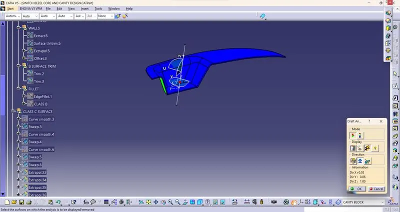
- Draft analysis can be done through tooling axis . select a compass on the draft analysis set on the tooling axis and lock it.
- Select the material option customized view parameters click ok.
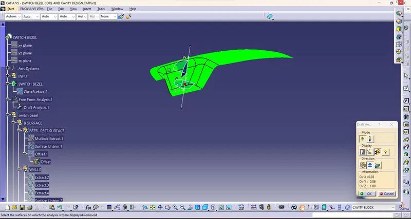
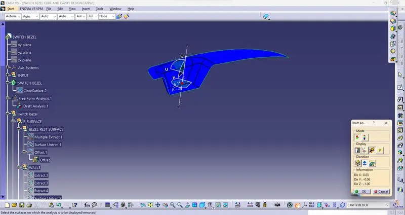
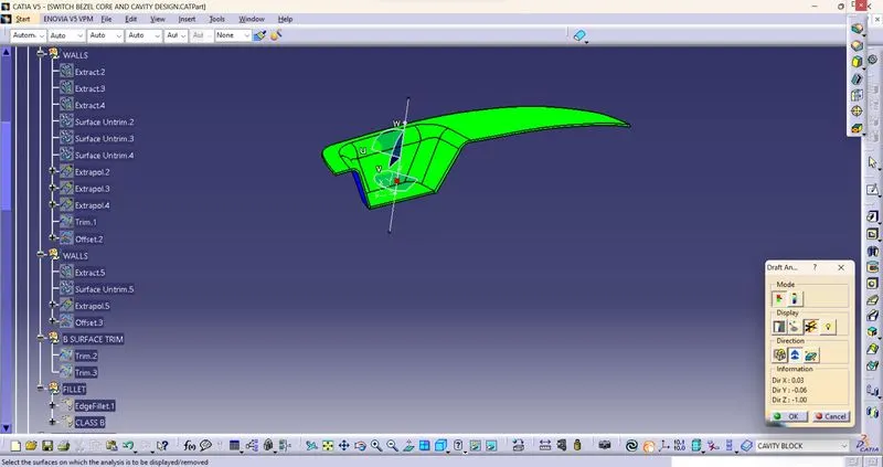
- click on the surface it will be visible as green in colour. Class A and Class C surface are in positive angle and Class B to be negative angle.
Tooling axis:
- Commonly we are consider holes in the class A surface than class A engineer was consider to cosntruct a tooling axis from centre of the circle
- But here hole is not available so we have to create a point on a Base surface as 0 than create a axis system.
- use positioned sketch take yz as plane create intersection on the class -A hide class-A create lines on the sides of boundary bisect them.
- yz tooling axis was formed.
- Again create positioned sketch take zx as axis create intersectio on the surface sketch a line on the side boundary and another side was not appear.
- so we have to create a 3degree line axis as zx tooling axis.
- Bisect the yz and zx tooling axis finally main tooling axis was appeared remaining lines are to be hide.
- Use this tooling axis do the drafting analysis on the Class-A surface for intial draft analysis.
Construction:
For every surface geometric set are to be added to choose easy to understand .
Body was in the part body.
Class -B surface:
- After creating a tooling axis select the arm rest on the class-A extract it and do untrim operation than offset the surface as 2.5mm below direction.
- Select the side phases extract them and untrim the surfaces give extrapolated the edges to increase the size trim the unwanted material.Finally offset the sides as 2.5mm in reverse direction.
- select the base extract the phase untrim the surface increse the size through extrapolated command offset with 2.5mm in reverse direction and trim with side phases required shape appear.
- Finally trim with the arm rest with last trim to get a required shape as Class-A.
- Fillets are to be given as 15radius for the side phase and 15-2.5 was given on the arm rest fillet edge because it is to be match to class-A to decrease thickness from the surface so we are given that radius to match.
Class -C surface:
- Unhide the Class-A and main tooling axis to create class -c.
- Here curves are not smooth so boundary line not worked so we have use curve smooth command to curve can be change as smooth with out any deviations..
- Create a boundary for class -A using curve smooth command take a reference as boundary of arm rest convert into two halfs through limit inthe boundary command select sweep command and draft direction given guided curve smooth and draft direct for tooling axis select outer surface arrow to form .
- Remain half to be converted into 3 halfs this can be done through multiextract and boundary commands.
- left side half was done curve smooth select extrapolates select each pont on the side upto base surace than click curvature. Use sweep command and draft direction given guided curve for curve smooth and draft direction for tooling axis select outer surface arrow to form.
- left side was do by curve smooth take a reference from boundary than use sweep command to give a guided curve as smooth curve and draft direction is tooling axis select outer arrow to form outer surface.
- Their is a little gap between the surfaces to fill through extrapolated the edges of the surface than trim the unwanted material to form a one surface.
- If their is any gap it was appear in green colour if their is no gaps it is appear in black at edges.
- angle was given as 3degree as minimum and length as 20mm . click ok as direction for outer surface for outer direction for inner circles is inner sweep direction.
- click ok Class -C surface was formed.
- Use join command to join the class-A and Class-C .
- For checking their any gaps in the surface to check use boundary to click on the surface its shows error means thier is no any gap.
Final trim:
- Select joint of Class-C and Class -A trim with class -B to remove unwanted material fianlly of unwanted object material was formed .
- For checking their any gaps in the surface to check use boundary to click on the surface its shows error means thier is no any gap.
After that Define part body with the command of closed surface in the part work bench to make a surface body into solid body.
Publications:
Class-A,Class-B,Class-C and Tooling Axis publications are in the Publication part body.
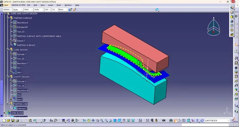
CORE AND CAVITY DESIGN:
- Core is can be named as projection it reflects the shape of a component and cavity is a depression of component .
- pressing the both core and cavity through injection moulding material was inserted due to pressure applied on the materail shape was formed
- Unhide the class-A extrpolate the boundary upto 15mm.
- unhide the solid body of a switch bezel do a draft analysis unhide extrpolate A surface.
- trim with C surface and then with B Surface.
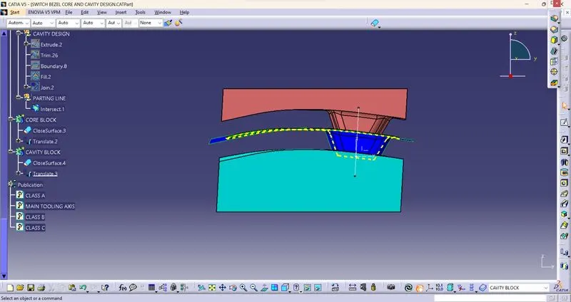
- parting surface with component was formed and check it is clear or not with click on tooling axis with normal surface . the visible parting surface contact with bottom of a switch bezel.
- Create a sketch as xy plane throughaxis system form a rectangle on the surface than boundarys are to be involved inside on the component.
CORE DESIGN:
- Extrude the sketch of a rectangle with direction of tooling axis as reference in both sides trim the bottom side and parting surface.
- upper extrude area create boundary than ir was fill the area with fill command than join both trim surface with fill suface.
- Create a body and turn the joint into solid surface use of solid command.
- Give a graphic colour to the solid body to differ.
- core was formed.
CAVITY DESIGN:
- Cavity was formed use sketch of a rectangle and extrude with direction of tooling axis as reference them upper part was trim than below part was form a boundary and fill the surface with a fill command
- use of join command join the trim surface with trim surface .
- Create a body and turn the joint into solid surface use of solid command.
- Give a graphic colour to the solid body to differ.
PARTING LINE:
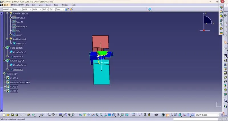
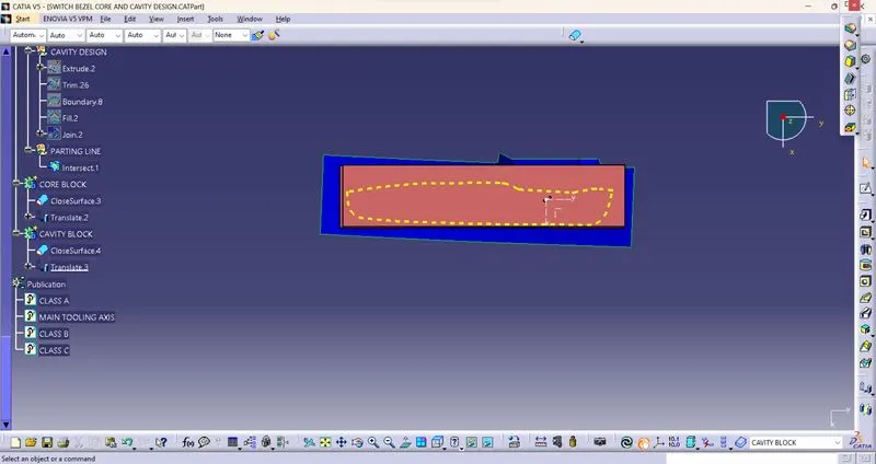
- it was formed through the intersection of class B with A and c surface parting line was formed it was mentioned in the yellow colour dotted line.
Parting surface :
- It was formed through split the parting surface component with intersecton of parting line..
- Finally parting surface also formed.
- use translate to core as upward direction and cavity as downward direction as certain distance with tooling axis as a direction reference.
SWITCH BEZEL DRAFT ANALYSIS ON A SURFACE:
SWITCH BEZEL DRAFT ANALYSIS AFTER SOLID SURFACE:
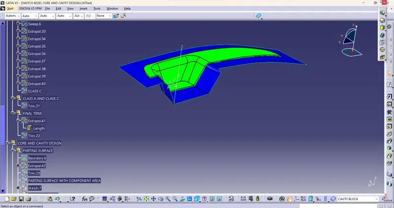
DIFFERENT VIEWS OF A SWITCH BEZEL CORE AND CAVITY :