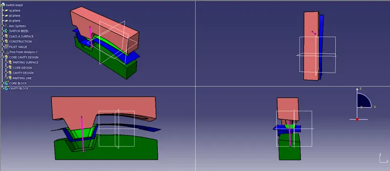
Week 8 - Challenge 6 - Core & Cavity Design
Aim
To create the Core and cavity blocks for the switch bezel.
Tooling axis
The axis is the direction in which the mold opens or else the core and cavity open. The tooling axis should help to clear components from the core and cavity, so it plays a very crucial role in plastic designing and manufacturing also.
Draft Analysis
First the class - A surface is checked before creating the Class - B & C surface and finally the solid body must be analysed . Both cab be done by following the below procedures.
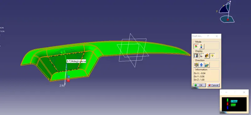
By changing the view mode to custom view parameters - Material mode then the feature draft analysis is enabled.
Then the compass was activated and placed with the tooling axis by dragging the redpointer and then lockes it
Then, by selecting the quick analysis mode, the nominal value will be 3 degrees and checked for the component's draft angle
The green colour area shows that it satisfies the 3 degree draft angle. If not satisfied then by using the Runnind point the area is measured and then altered to get a succesful draft for the created tooling direction.
Draft Analysis for Final Plastic Component
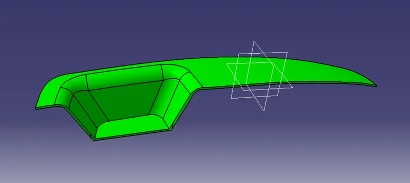
Parting line
- It is the line where the core and cavity intersect each other.
- The parting line lies on the B surface of the Plastic component to protect the A surface from the splash.
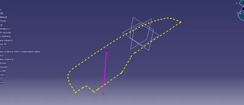
Parting Surface
- The surface where the core and cavity meet each other is called the Parting surface.
- The Parting surface also lies on the B surface side.
- The below screenshot shows the surface in pink color which represents the Parting surface and the green line represents the parting line.
- We can clearly see that the parting line and the parting surface are lying on the class B surface.
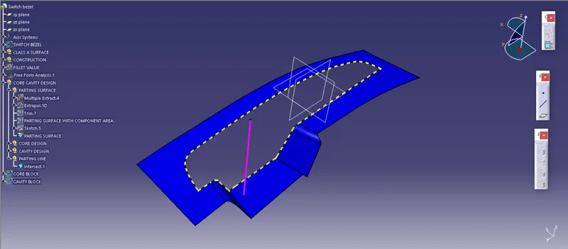
Parting surface with component
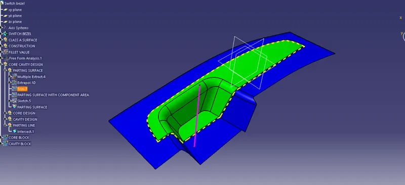
CORE BLOCK DESIGN
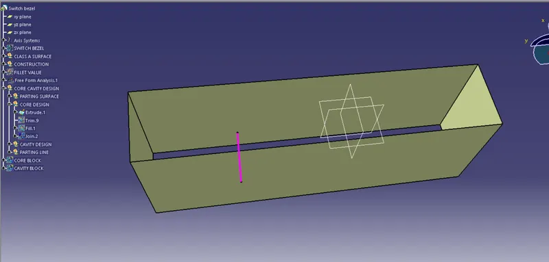
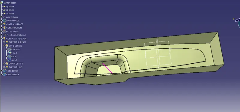
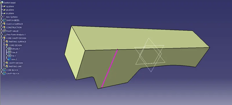
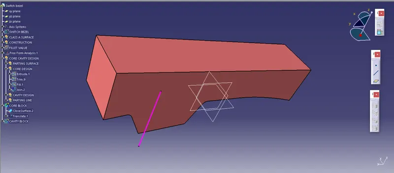
CAVITY BLOCK DESIGN
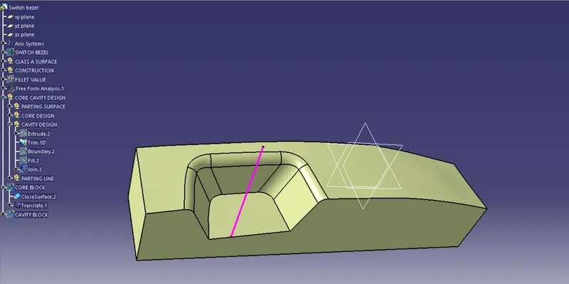
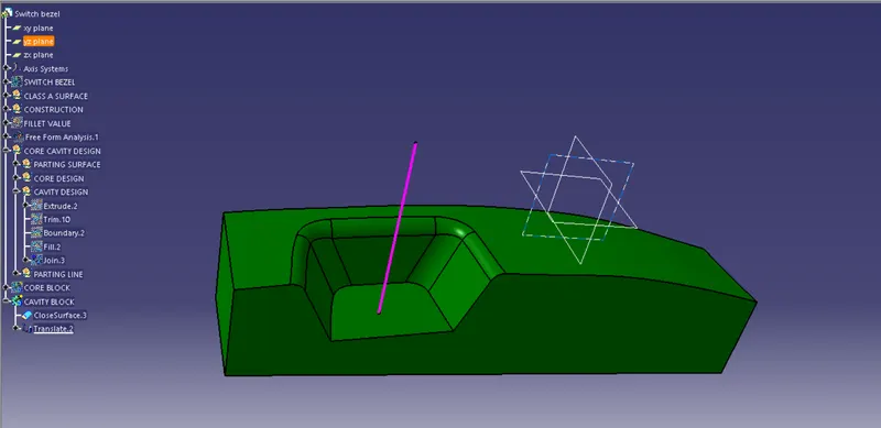
CORE , CAVITY , PARTING SURFACE AND COMPONENT
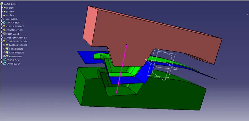
VARIOUS ORINTATION