Week 8 - Challenge 6 - Core & Cavity Design
CORE AND CAVITY DESIGN FOR SWITCH BEZEL
OBJECTIVE:
The aim of Challenge to Create Core and Cavity for Switch Bezel by taking input switch Bezel Part created and having Draft Analysis.
TOOLING AXIS:
Tooling axis is much more important in Designing Plastic components to analyse the Draft angle which is used to define the Direction in which mould core or cavity opens. The following steps used to create Tooling Axis.
- Created Sketch for Dummy Tooling Axis from input Class A surface between the faces of Y direction.
- Created another Sketch for Dummy Axis for X direction.
- Then Bisect the Axes to create main Tooling Axis.
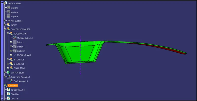
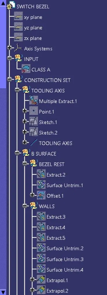
The above image shows the example of Tooling axis (can see in Feature Manager Tree)
DRAFT ANALYSIS:
Draft analysis is done after determining the tooling axis, draft analysis is used to check whether the minimum draft (3 degrees) is maintained or not. Compass is used to define the draft direction.
- The draft analysis is to identify the body is in proper draft angles or not.
- The normal draft angle of the body is 3 deg.
- The draft angle allows the part to remove or eject from the mould.
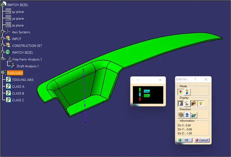
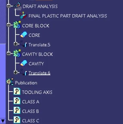
The above image shows the Final Plastic Component Draft Analysis.
CORE AND CAVITY:
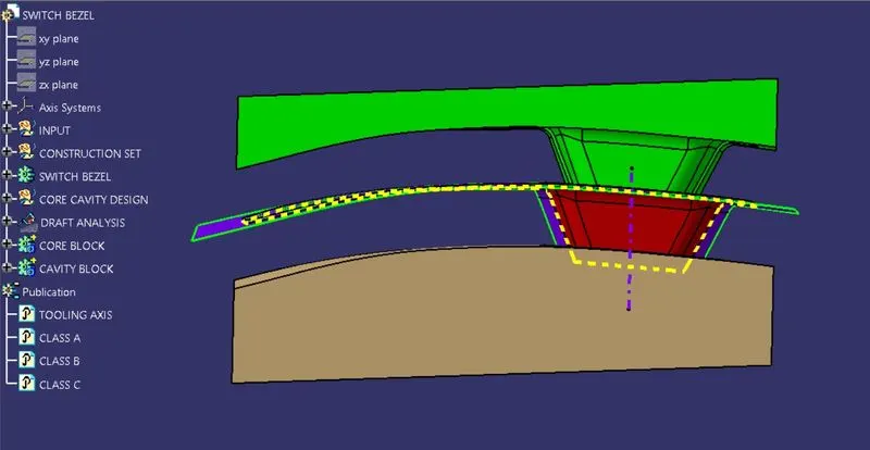
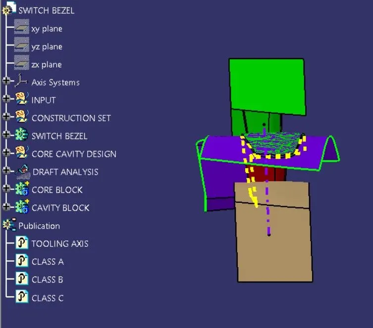
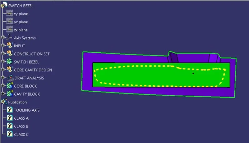
The core is the male part which forms the internal shape of molding. The cavity is the female part which forms external shape of molding. The Core and Cavities are divided by Parting line and Parting Surface.
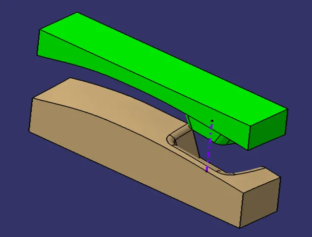
Above Image Shows Core (in Green Colour) and Cavity (in Wheatish Colour)
PARTING LINE
The parting line is where the two halves of the mold meet around the parameter of the part. All parting lines need to seal properly when the mold is clamped in a molding machine.
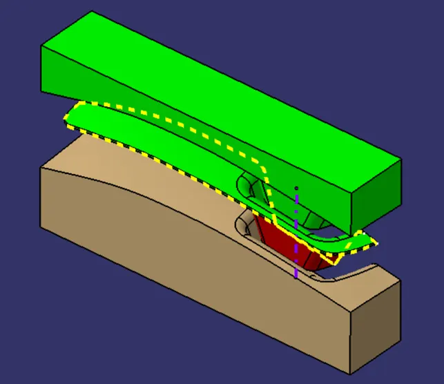
In the above image Parting line shown with Yellow dashed line.
PARTING SURFACE
A parting surface is a surface that separates the mold block into two parts – the core and the cavity. Consider a model, as shown in the image above. As you can see, the model is a hollow plastic component. To make a mold for this part, you should first select a parting line for the mold.
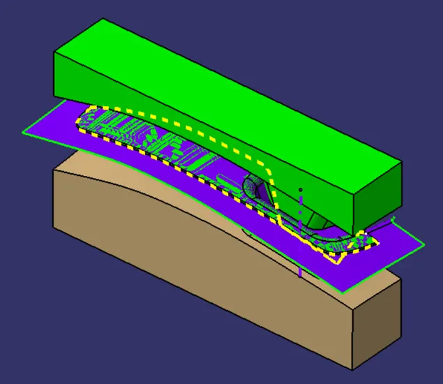
In the above Image Parting Surface shown in Blue Colour.
FRONT VIEW:
SIDE VIEW:
TOP VIEW:
ISOMETRIC VIEW:
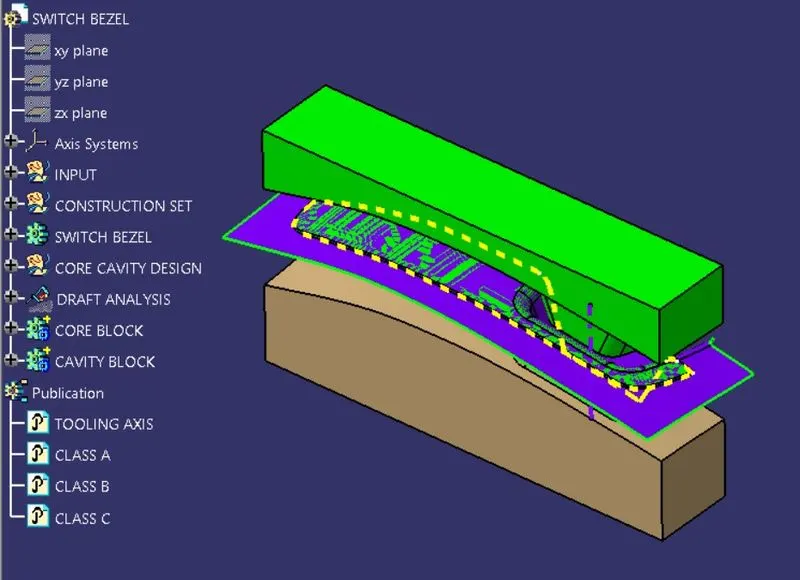
CORE & CAVITY WITH PARTING LINE & SURFACE:
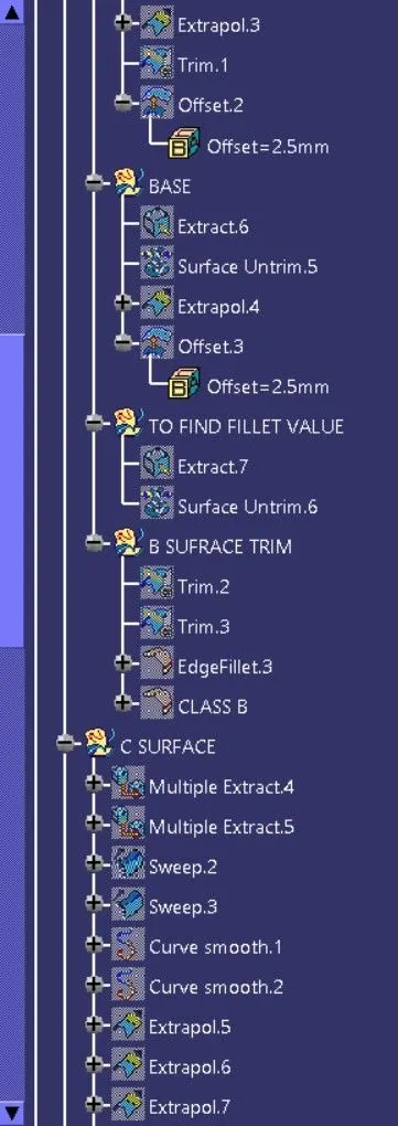
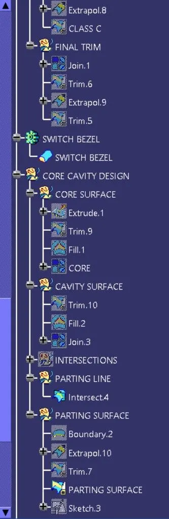
FEATURE MANAGER TREE: