Week 8 - Challenge 6 - Core & Cavity Design
Aim -The main objective of this challenge is to design a Core and Cavity for a Switch Bezel' in CATIA V5 with the help of a surface workbench.
Before we design the core and cavity, we should perform a draft analysis on the solid part body of the switch bezel.
Draft Analysis -
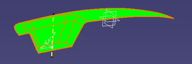
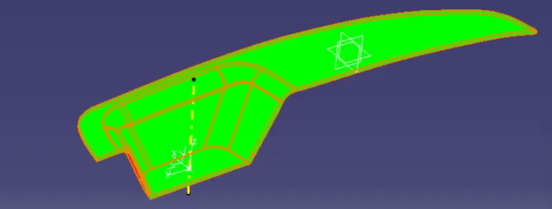
Draft Analysis is used to check the whether the minimum draft of 3deg is maintained or not.The draft analysis command enables you to detect if the part you drafted will be easily removed. This type of analysis is performed based on color ranges identifying zones on the analyzed element where the deviation from the draft direction at any point, corresponds to specified values.
1.Draft Analysis of Class A
2.Draft Analysis Of Switch Bezel
Core and Cavity Design -
- The Mould Core & Cavity are the shaped sections in either half of the mould tool which give the plastic product its final shape.
- The hot molten material is injected into the core & cavity and then sets hard into shape. The design of the core & cavity is essential in the correct formation of the product. The sequence of events during the injection mould of a plastic part is called the injection molding cycle.
- The cycle begins when the mould closes, followed by the injection of the polymer into the mould cavity.
- A core is usually made of the best quality sand and is placed into the desired position in the mould cavity. Core prints are added to both sides of the pattern to create impressions that allow the core to be supported and held at both ends.
Core Design:
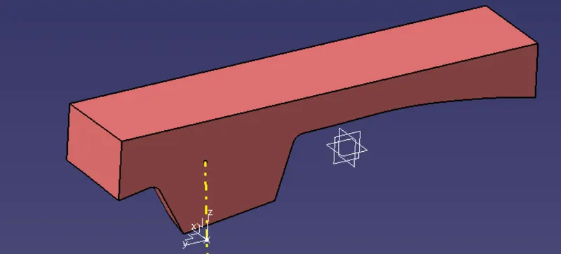
Initially, we have taken the boundary of the class A surface to extrapolate it. After extrapolating the class A surface ,we trimmed extrapolated class A surface and class C surface (join of class A and sweeped surface), after that we trimmed the class B surface with Trim.To create the 'Parting surface'. Now we draw a rectangle, which does not exceed the boundary of the parting surface.
Now we extruded the sketch along the tooling axis, after extruding the rectangular sketch, trimmed both the parting surface and rectangular extrude to remove the lower side of the parting surface. I filled the upper surface to make a closed surface by joining the filled and trimmed surface. Now we make the closed surface into a solid body, the obtained solid part body is our CORE bock.
Cavity Design:
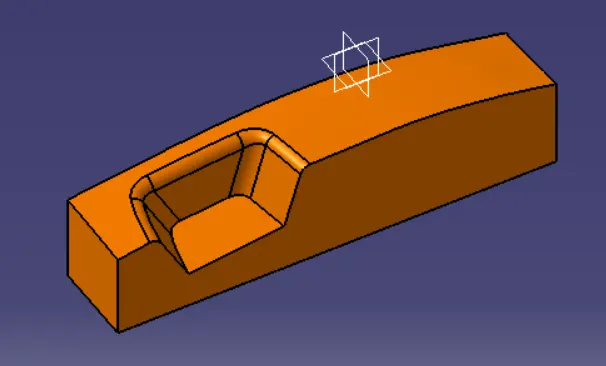
To create the cavity block, We trimmed the rectangular extrude with a class B surface to remove the surface which is the upper side of it. After that, We filler the surface which is opened, to make a closed surface by joining both trim and filled surface. Now create a solid body from the closed surface by using the closed surface. The obtained part body from the closed surface is our CAVITY block.
Parting line and Parting surface -
Parting Line -
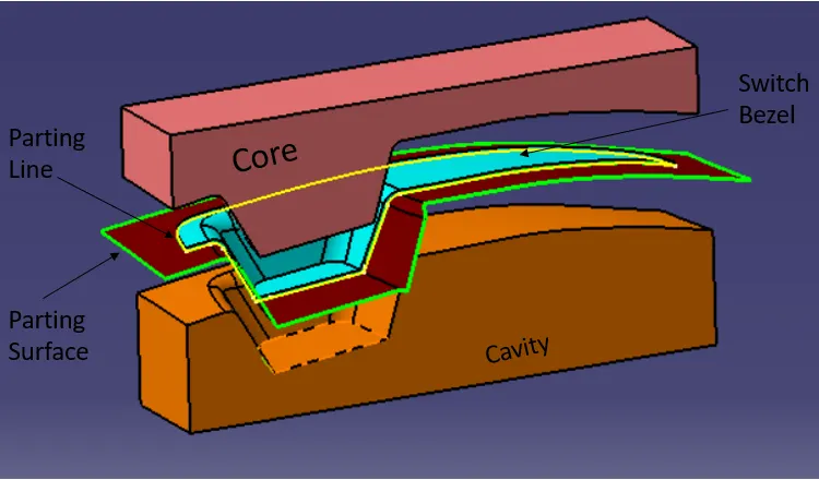
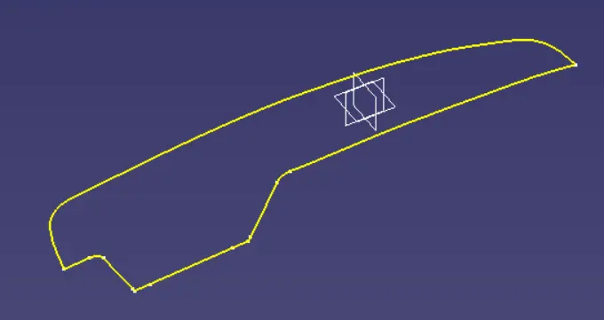
- A parting line, in the industrial casting of molds, is the borderline in which draft angles change direction. That is, it is the dividing line that splits the core and cavity halves of a molded part. It is sometimes a starting point for the mold parting surface.
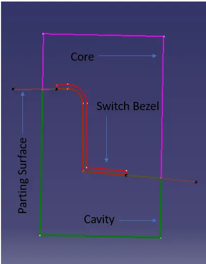
- Here intersecting the parting surface, core, and cavity across the ZX plane gives the intersecting line that tells the parting line.
Parting surface:
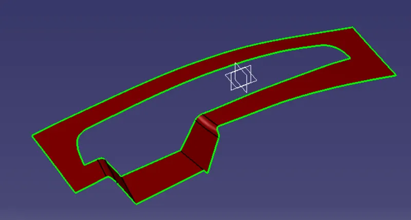
The parting surface of a mould are those surfaces of both mould plates adjacent to the impressions which butt together to form a seal and prevent the loss of plastic material from the impression. The parting surfaces of a mould are those portion of both
mould plates, adjacent to the impressions, which butt together to form a seal and prevent the loss of plastic material from the impression.
Intersection of Core,Cavity,Switch Bezel and Parting Surface -