Week 8 - Challenge 6 - Core & Cavity Design
Tooling Axis:-
To Import Class A surface in the drawing.
Using intersection method and bisecting line method created Tooling Axis.
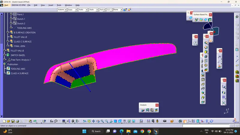
Explaining the Draft Analysis and the Tooling Axis creation.
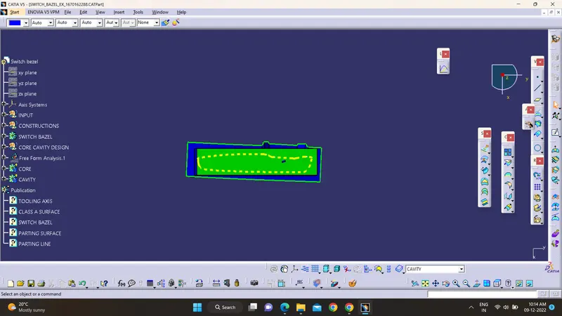
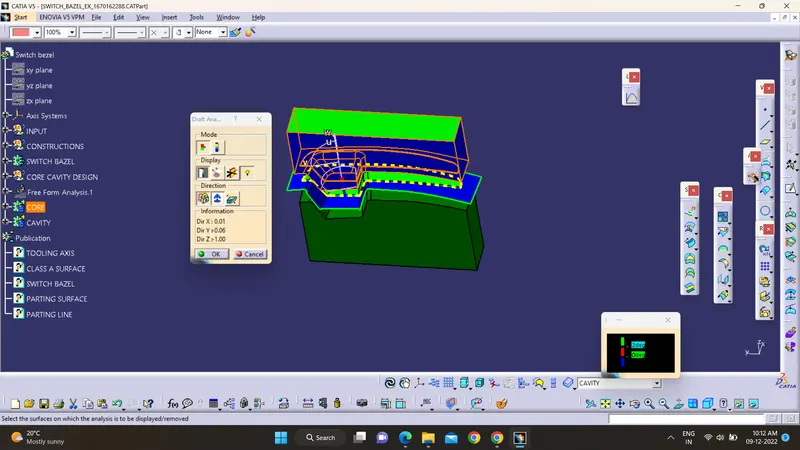
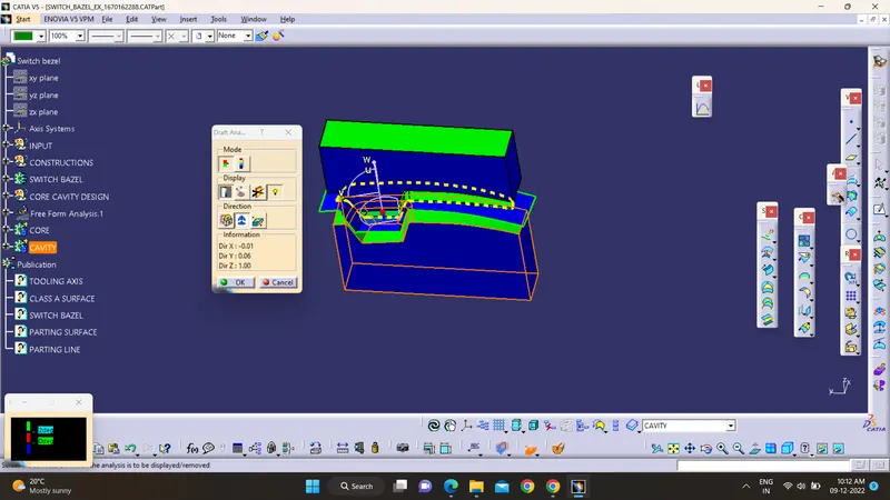
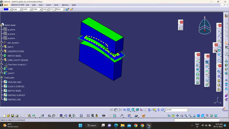
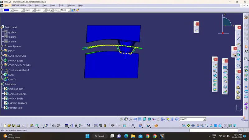
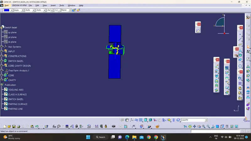
after that we need to perform Draft Analysis on CLOSED PART BODY and for that we need to attach Axis System to TOOLING AXIS after that we need to see the our surface having what Draft angle actually general draft angle ranges from 0.5 degree to 3 degree then we can see two colors on after draft anaysis it is of GREEN and Bottom of BLUE which represents that our Draft analysis is right and if we can see some RED patches on itr then our draft angle needs to be update or change then we need to check suitable draft value for it and need to Rectify that.
For creating the tooling axis first of all need to extrapolate the base surface of the class A. and than take the point on the surface. After that create the intersect of the class A surface in the required plane and than make a bisecting line between the straight two line.
The bisecting line is our tooling Axis.
- Screenshots of the Draft analysis report for both the switch bezel plastic component
ISO VIEW
FRONT VIEW
SIDE VIEW
TOP VIEW