Week 8 - Challenge 6 - Core & Cavity Design
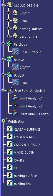
AIM: Creating the core and cavity blocks for the SWITCH BEZEL Design.
TOOLING AXIS:
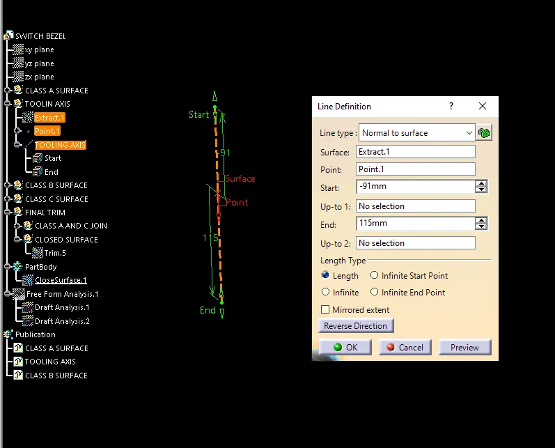
The direction in which the mold or core and cavity opens is the tooling axis. In moulding , the direction in which the mould (core and cavity) is allowed to moveis called tooling direcrtion or tooling axis. Most of the times its the core which moves along the tooling axis and in few cases cavity may also move along the tooling axis based on the design requirement of the model.
*Tooling axis can be created by 3 methods:
1 - With respect to the axis system; that is along the axis x , along axis y , along axis z.
2 - Normal to surface.
3 - Bisecting method.
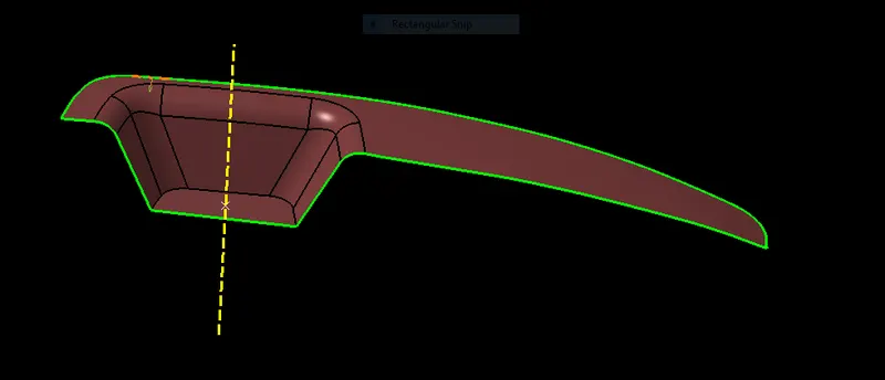
In this model the tooling axis is created normal to the flat base surface of the class A surface.
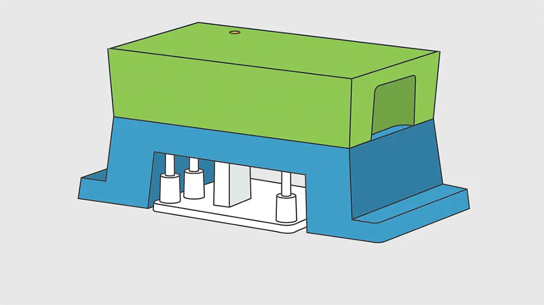
CORE: The core is the male part which forms the internal shape of molding, the upper half of the mold where the plastic part is injected from is called CORE.
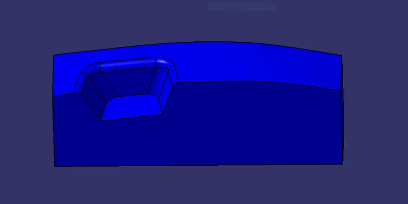
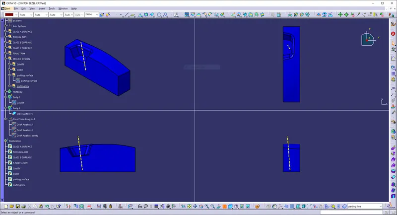
CAVITY: The female part which forms the external shape of molding.
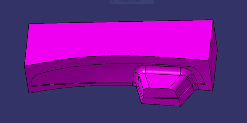
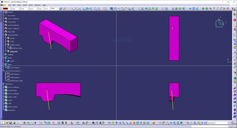
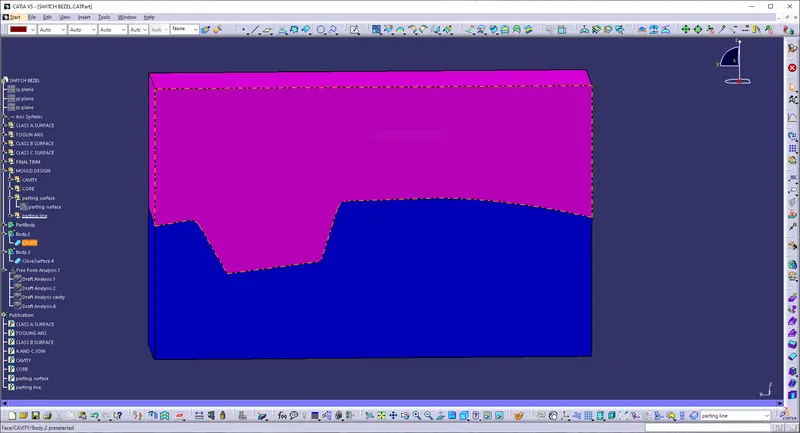
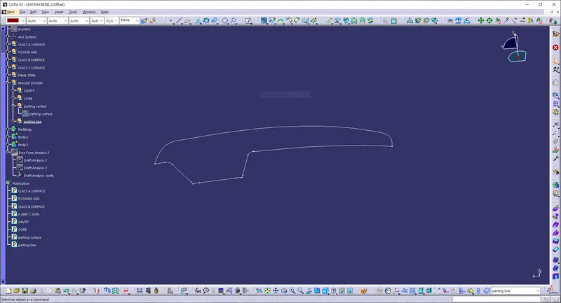
PARTING LINE: The parting line of a die cast component represent where the two different sides of the mold come together.This line often marks the border between the inside and outside of the part.The location of parting line indicates which side of the die is the cover and which is considered the ejector.
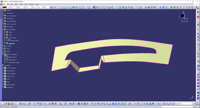
PARTING SURFACE: A parting surface is a surface in the model that you designate to a split a workpiece, die block, or another volume. It is designed for the removal of plastic product and the cold slug.The parting surface is where the core meets the cavity.
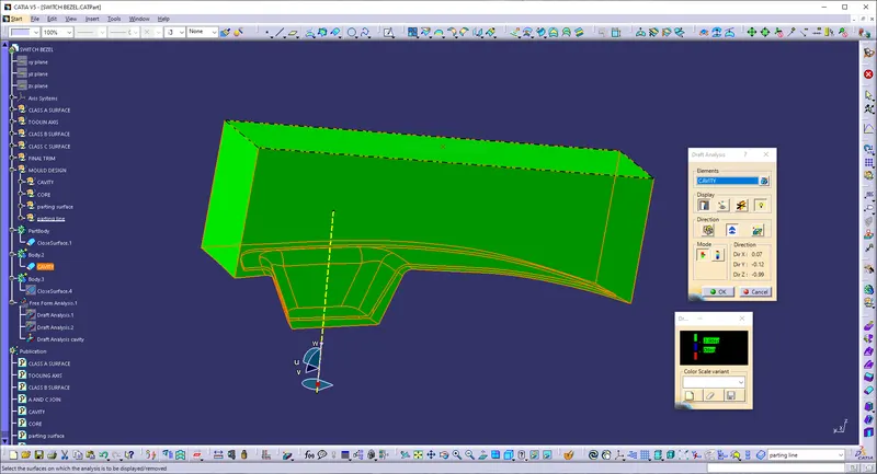
DRAFT ANALYSIS OF CAVITY:
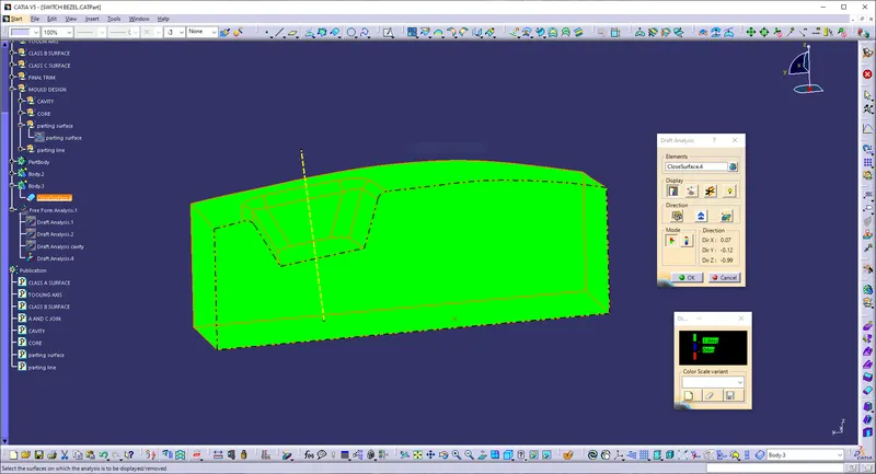
DRAFT ANALYSIS OF CORE:
EJECTED PLASTIC PRODUCT (SWITCH BEZEL):
FEATURE TREE: