Week 8 - Challenge 4 - Bumper
PLASTIC BUMPER DESING OF A CAR:
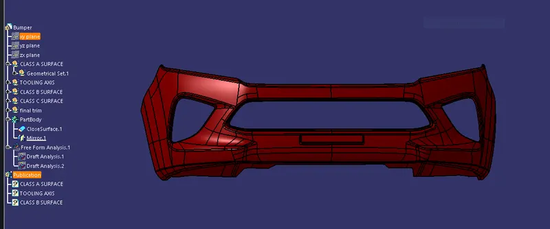
Creating the BUMPER plastic component through the given Class-A surface. To begin, the tooling axis for the given Class-A Surface should be created.
TOOLING AXIS:
The direction in which the mold or core and cavity opens is the tooling axis. In moulding , the direction in which the mould (core and cavity) is allowed to moveis called tooling direcrtion or tooling axis. Most of the times its the core which moves along the tooling axis and in few cases cavity may also move along the tooling axis based on the design requirement of the model.
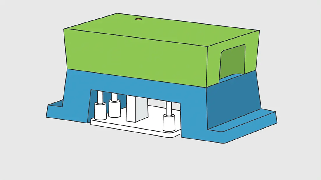
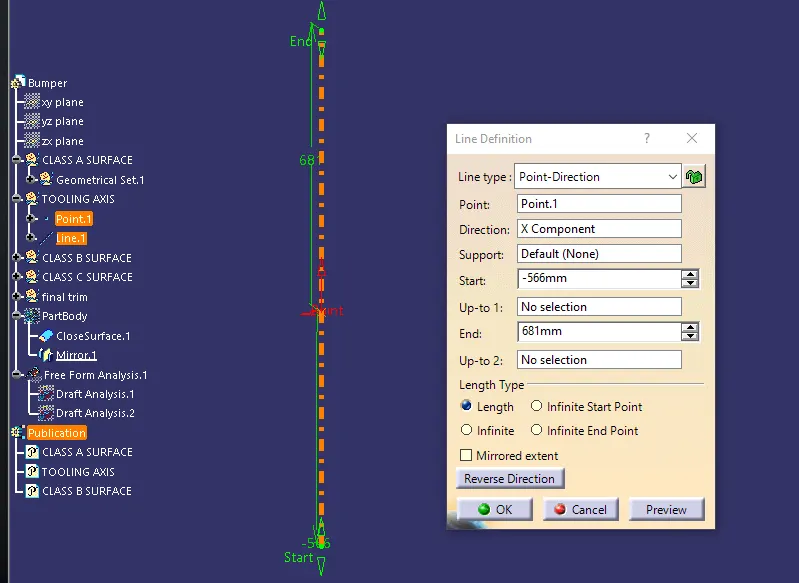
*Tooling axis can be created by 3 methods:
1 - With respect to the axis system; that is along the axis x , along axis y , along axis z.
2 - Normal to surface.
3 - Bisecting method.
In this model the tooling axis is created along the X-axis in the center of grill hole on the class A surface.
MATERIAL USE:
The material used in BUMPER is thermo plastic because it is placed outside of a car and reqiuresgood asthetic finish and chemical resistant which can be achieved by thermo plastic.
Acrylonitrile Butadiene Styrene (ABS):
Using ABS material for these components lowers the overall weight of an automobile, thus creating high demand. Excellent impact resistance & aesthetic qualities.
CLASS A SURFACE:
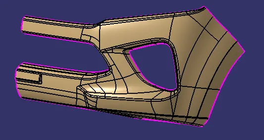
Class A surface means those surfaces which are visible in a product either interior or exterior. It describes the final production surface data for the aesthetic parts of the car.
The below image shows the Class A surface :
CLASS B SURFACE:
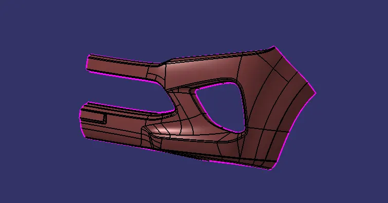
Class B surfaces are the secondary surfaces that you can see sometimes, but are less important . This surface is not visible to the coustomer most of the times hence the surface finish is not as good as class A surface because it contains the ejector pins mark on it.
The below image shows the Class B surface :
CLASS C SURFACE:
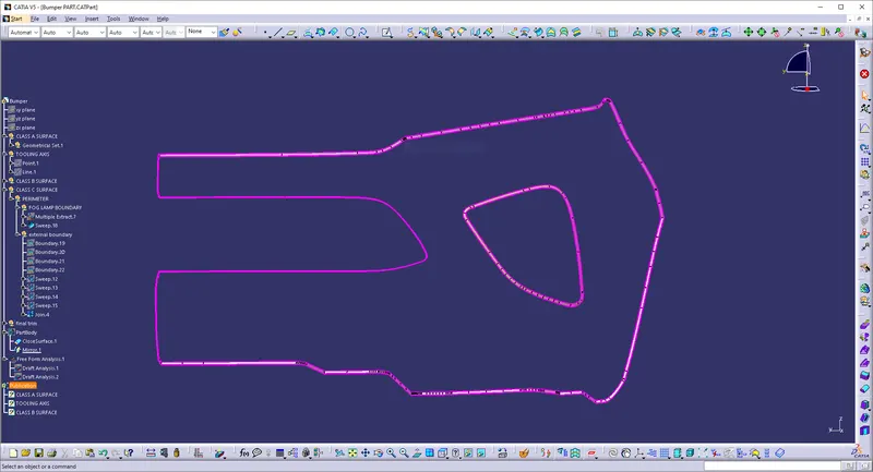
It is the surface which connects the class A surface and the class B surface . It can also be termed as the thickened surface . It is the surface which gives thickness to the designed component. But in this model the class c surface is perpendicular to tooling axis and parallel to core and cavity, therefore the class c surface is created 90 degree to the extracted boundary surface of class A surface.
The below image shows the Class C surface :
DRAFT ANALYSIS:
The draft analysis technique is used to analyze whether our part model created in CAD is manufacturable based on the draft condition applied. It shows wether the component designed can be ejected out from the mould with out causing any damage to the product.
With draft analysis, you can verify draft angles, examine angle changes within a face, as well as locate parting lines, injection, and ejection surfaces in parts.
Draft is a taper applied to the faces of the part that prevent them from being parallel to the motion of the mold opening. In this model the draft angle is 90 degree with respect to class A surface.
But here the class c surface is perpendicular to tooling axis and parallel to core and cavity, therefore the class c surface is created 90 degree to the extracted boundary surface of class A surface.
It is a tool that allows the user to ‘see’ whether the part they are designing can be removed from the tool being used to make it. In the case of plastic injection molded parts it also allows the designer to see if there is enough draft on the part to ensure that it can be correctly grained.
DRAFT ANALYSIS ON CLASS A SURFACE:
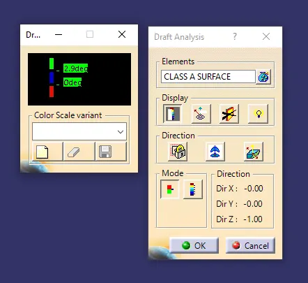
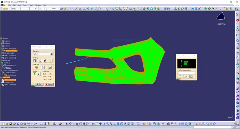
Here in this model the draft analysis was first conducted on the class A surface to check wether the class A surface is manufacturable . If the surface turns in to green colour with out any red or blue patches on the top surface then it is manufacturable.
DRAFT ANALYSIS ON PART BODY:
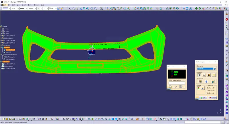
After completing the design and converting the model in to solid using closedsurface then the draft analysis is performed on the part body to verify wether the created model is manufacturable or not.On performing draft analysis if the model turns in to green colour then the model can be manufactured.
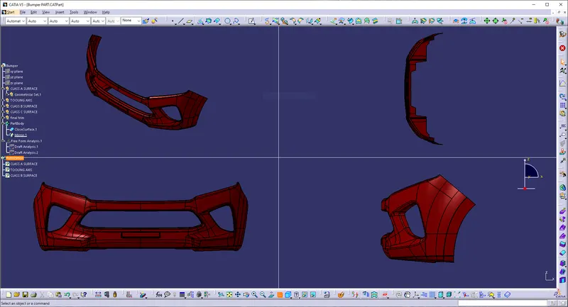
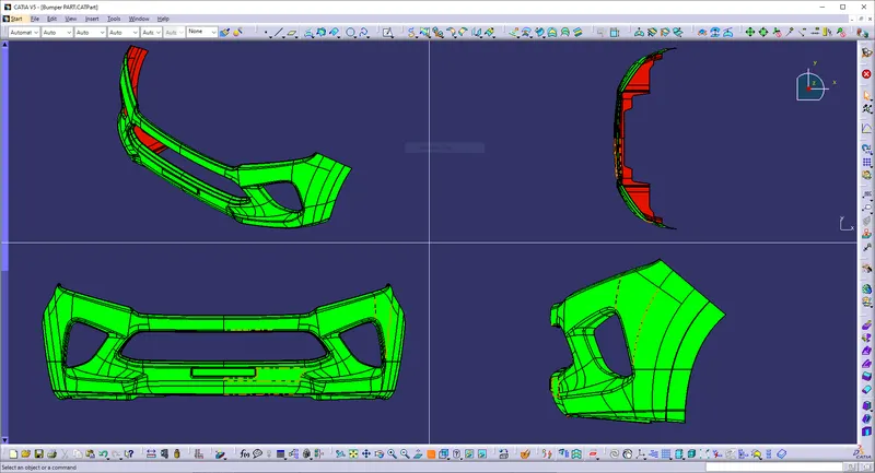
VARIOUS VIEWS OF COIN HOLDER:
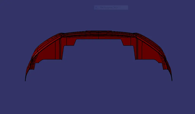
TOP VIEW :
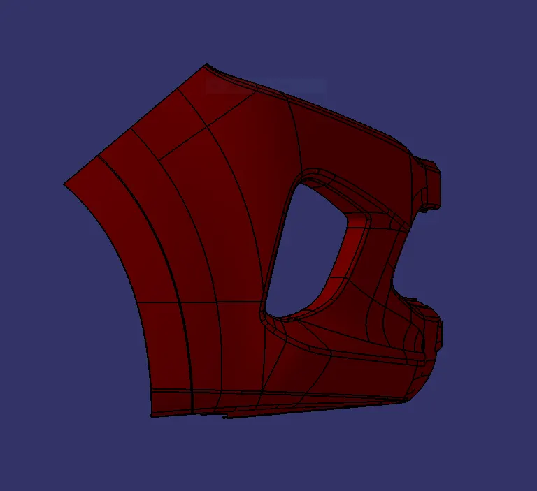
SIDE VIEW:
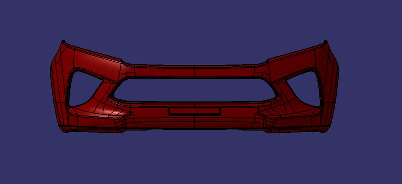
FRONT VIEW:
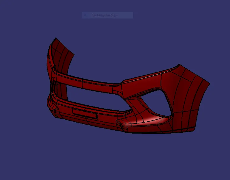
ISOMETRI VIEW:
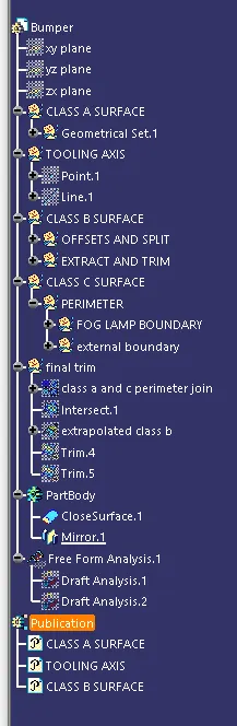
FEATURE TREE :