Week 8 - Challenge 6 - Core & Cavity Design
Report for designing of Core and Cavity for Switch Bezel
Aim: To Create the Core and cavity blocks for the switch bezel design
To Create Core, Cavity and Parting surface for the given component along the Tooling Axis.
Introduction:
The core and cavity are the two halves of the mold where the hot molten plastic material is injected into the core and cavity and the gap between the core and cavity is filled with the hot molten material during the molding process and then hardened into the final shape. The mold design of the core and cavity is critical to the proper molding of the product. The core is the raised part of the mold and the cavity is the recessed part of the mold. The core side contains the ejection actuator, which controls the ejector pins.
Tooling Axis
The tooling axis is the direction of drawing a sheet metal where the finished component is easily ejected on a particular direction and axis.
In Molding, machine arrangement is given to open the mould along a direction which is known as Tooling Direction. In other words. The mould is built from two separate halves (Core and Cavity) and tooling direction basically defines the direction of mould pulls apart.
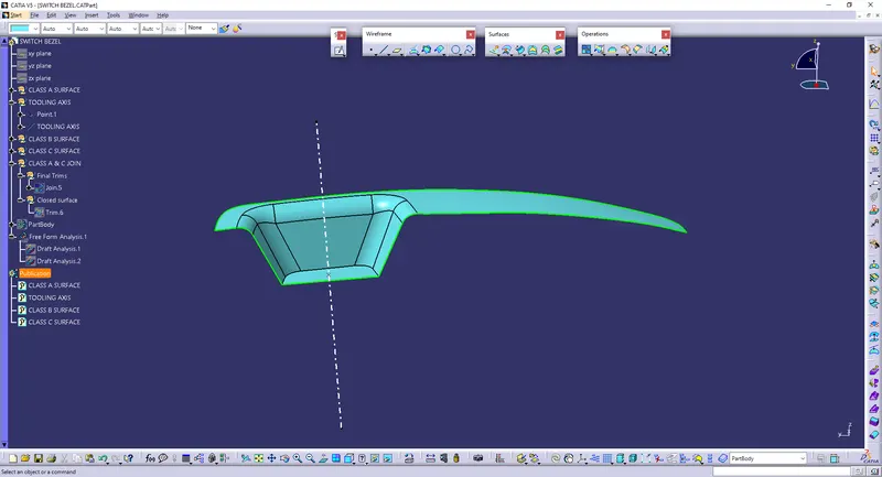
In the given model we are using the Normal To Surface method.
For creation of tooling axis, a point is inserted on the one surface of class A surface through which tooling axis can be drawn in Z direction.
Creation of Cavity:
Cavity is the combined open area of the molding material and core, where the metal is poured to produce the casting.
The cavity is the female part which forms external shape of molding.
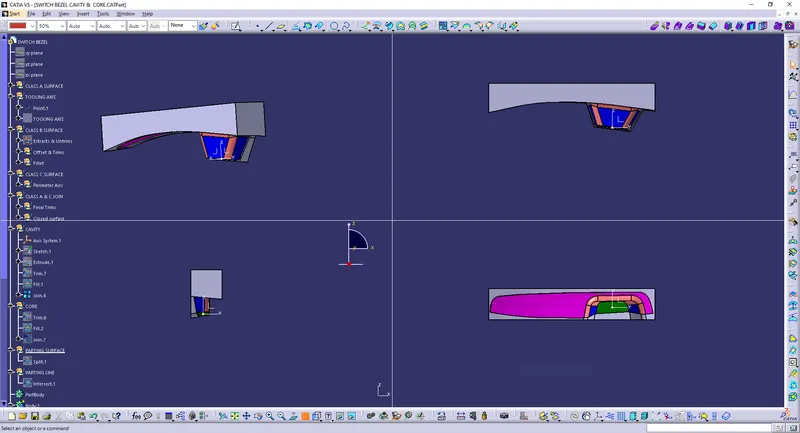
The Rectangular extrude was used to create the cavity as well. This extrude was Trimmed with the Class B to form the Cavity part. The Cavity was closed at the top using Fill command and was further joined using Join command.
Created Cavity in closed surface:
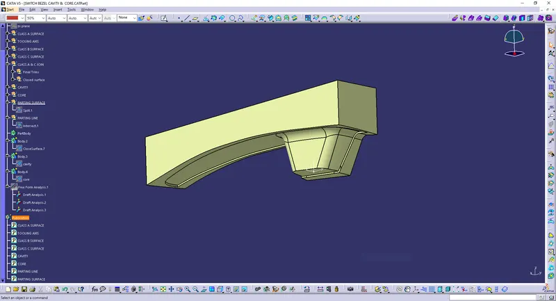
Images of Cavity after making it as a Solid body:
Creation of Core:
Core is a preformed, bonded, sand insert placed into the mold to shape the interior of a casting or a part of the casting that cannot be shaped by the pattern. Core is the male part which forms the internal shape of molding. Cores are often used to create hollow sections or cavities in a casting.
A Rectangular shape was formed and extruded along the tooling axis such that it stays inside the region of the Parting surface.
This extrude was Trimmed with the Parting surface with component to form the Core part. The Core was closed at the top using Fill command and was further joined using Join command.
Created Core in closed surface:
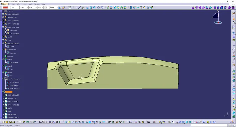
Images of Core after making it as a Solid body:
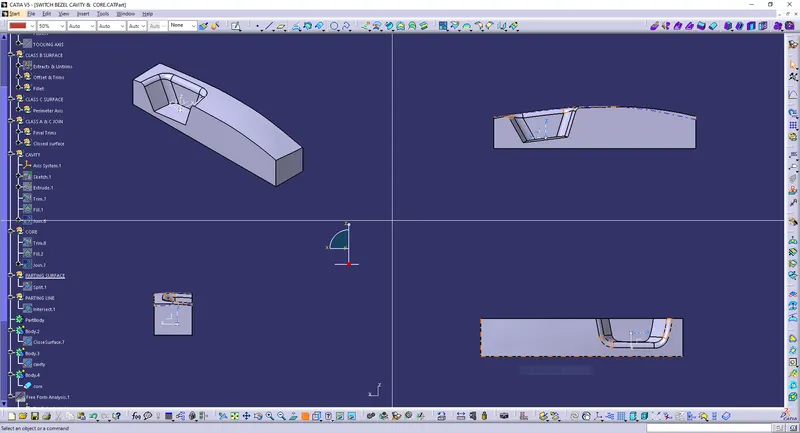
Draft Analysis Report of Core and Cavity:
In the criteria of making a plastic material, the mold should release the material when finished. if the mold surfaces are 90 degrees the material won't release from the mold because of friction due to contraction of material when cooled.The ejection of the part from mold depends on the draft. A zero draft can result in difficult or no ejection.
The Drafting analysis was performed using the Feature Draft Analysis command. Using this command the compass was set on the main tooling axis and the Draft angle was changed to 2.9 degree.
Draft analysis of Cavity:
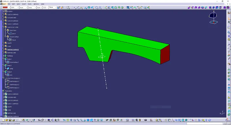
Draft analysis of Core:
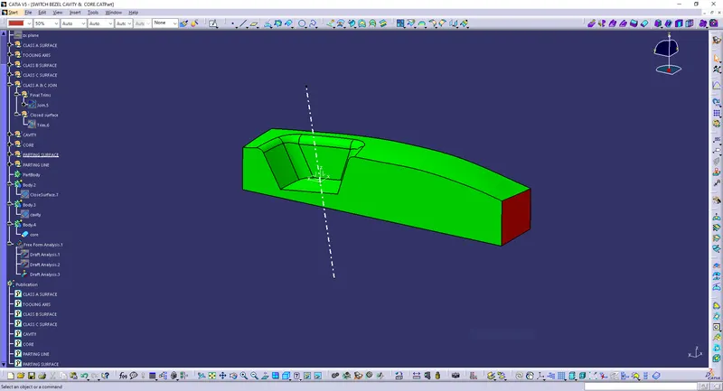
Parting Line:
Parting line is the area in which parting surface and component meets. Or it is a junction between core and cavity and the parting surface has some set of rules because the product quality mostly depends on the parting surface.
Initially the Class A surface was Extrapolated. It was then Trimmed with the Class C surface.
This output was further trimmed with Class B surface along with the component. The Parting line was created as an Intersect with Class B with a Trimmed surface.
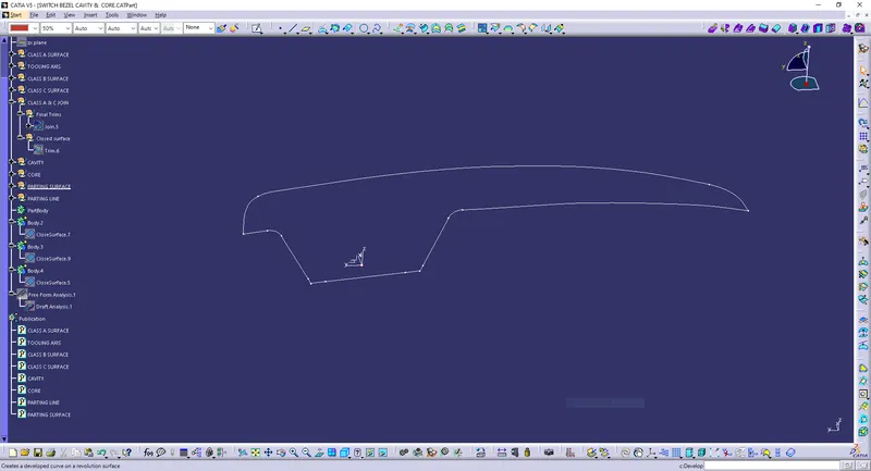
Parting Surface:
Mold has two major components one is core and another is cavity .during the injecction molding process, these two halves are pressed tightly from a sealed hollow to avoid the melt flow leakage and maintain certain holding pressure, the pressed surface are called parting surface , usually parting surface are the biggest projection outline of the part.
The Parting surface was obtained by Splitting the Parting surface with component with the Parting line.
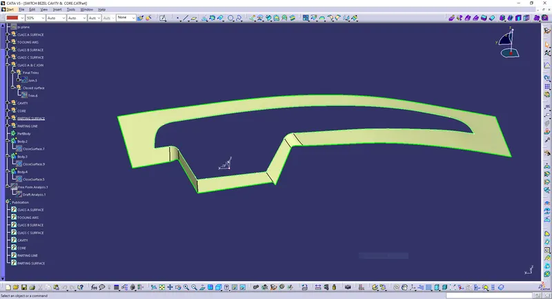
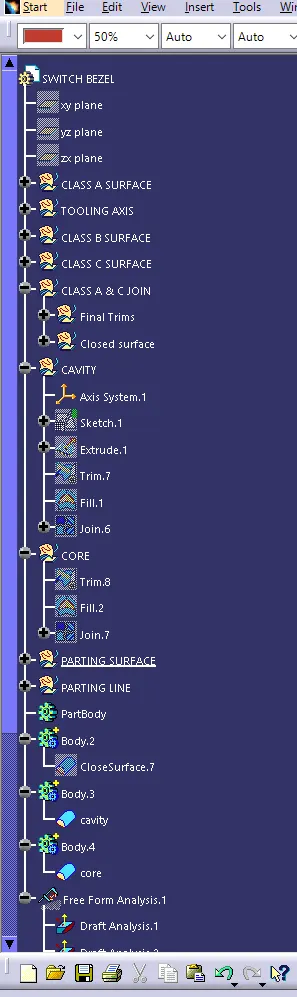
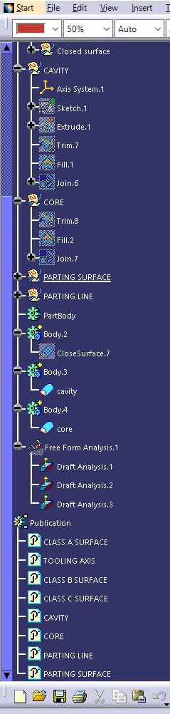
Tree structure: