Week 8 - Challenge 1 - Base Bracket Design
Base Bracket Design Report:
First Inserted the input surface / Class A Surface and then joined the each and every surface with the merging distance of 0.1mm.
Creation of Tooling Axis
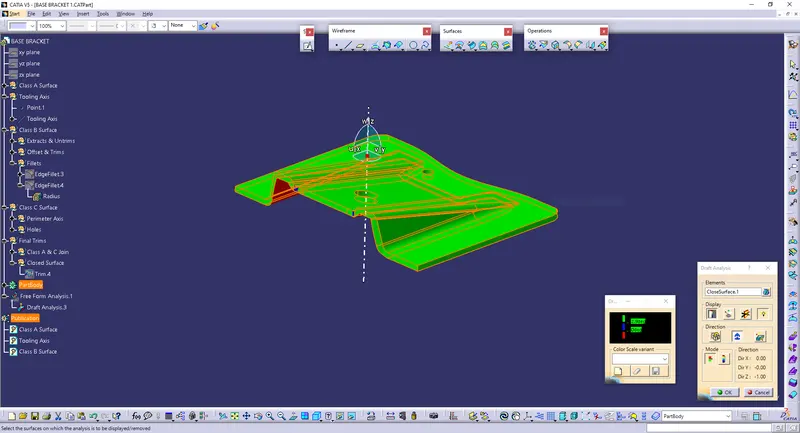
First, find the necessary and ideal plane that is suited for making a tooling axis. So selected the circle which is in the top view and then inserted point on the of circle and created a line along the Z-Axis with respect to the point and then made it as the tooling axis along the Z-Axis by considering the part geometry. In the Z direction the tooling axis clears the holes on top and as well as the draft on other sides of the part. Hence here the method used is Along to any Axis.
Tooling Axis with reference to Class A Surface:
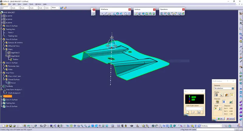
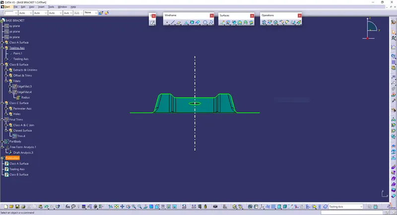
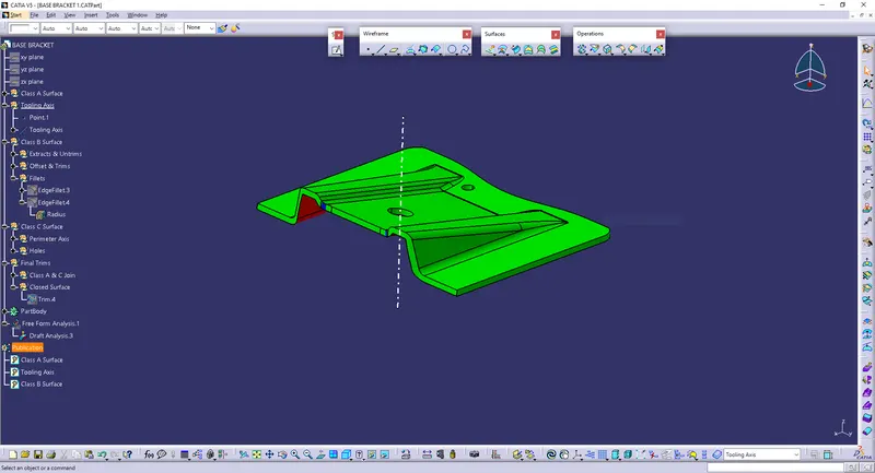
Tooling Axis after creating Class A, B, and C:
Material Selection:
- The type of plastic here used is thermoplastic because the part can be manufactured by the injection molding.
- Thus the plastic used is thermoplastics. Under group of thermoplastic we can choose materials such as:
- Polycarbonate plastic because it as the characteristics of extremely strong and impact-resistant, possesses inherent design flexibility.
- Polypropylene, it is a flexible thermoplastics, will not crack under repeated stress, heat resistant, acid resistance, and cheap.
- Polyvinly Chloride used because it is manufactured to possess rigid or flexible properties, it has the ability to blend with other materials.
- Acrylonitrile Butadiene Styrene (ABS) has the features like robust, flexible, glossy, highly processable, and impact resistant.
Class A, B and C:
Class A Surface:
Class A surface is the toper most layer or it is the asethetic surface given as input for creating the Class B Surface.
Class B Surface:
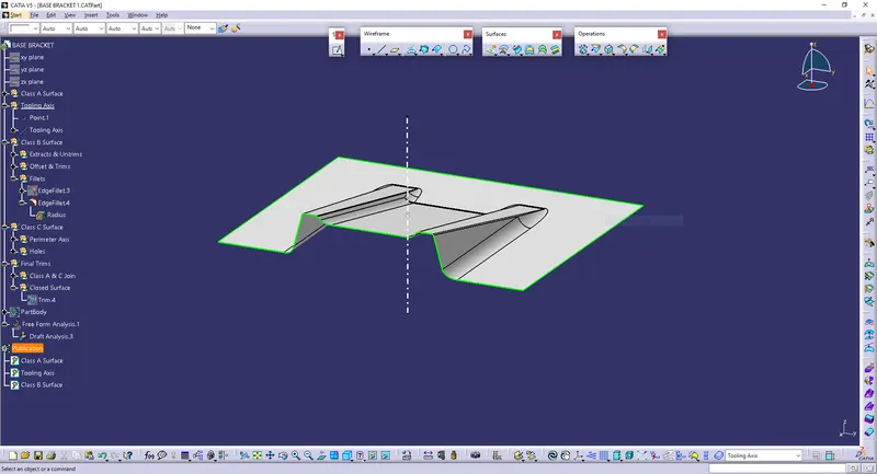
Class B Surface the bottom layer of Class A Surface.
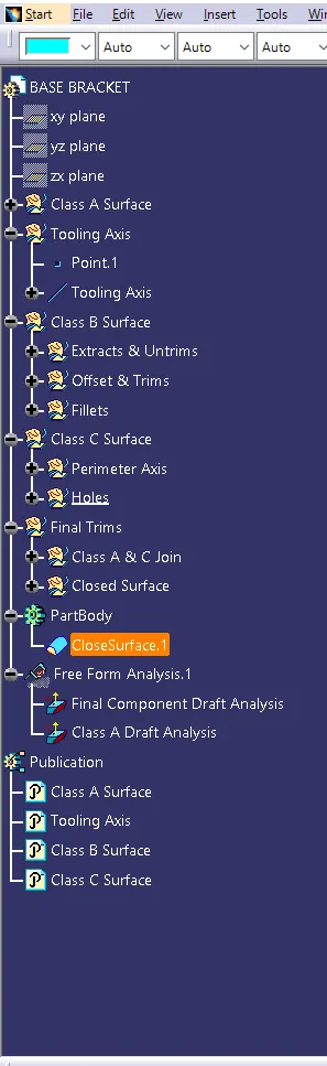
- In order to create Class B, we first removed the parent surface from Class A and then perform the operations such as extract, untrim, offset, and then trim it.
- After untriming, surfaces are then offset to the required thickness.
- After offsetting, all the surfaces are trimmed into the required shape.
- Required fillets are given to the surfaces.
Final Class B Surface created:
Class C Surface:
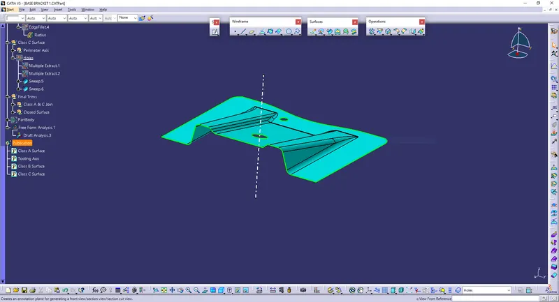
The Class C finish allows more imperfections than Class A or B. Class C is often specified for interior surfaces not readily visible, surfaces that will be covered by another part when assembled, or surfaces which the Customer feels do not need to meet a high cosmetic finish.
- For creating this surface we have extracted the boundry of Class A using multi-extract and then converted to smooth curve.
- Go to the "line" command in the "profile" block of the sweep command; the subtype is "with draft direction."
- Now this smooth curve is swept along the draft direction with a 3deg draft.
- For that select the smooth curve and tooling axis, give 3 deg in the angle with respect to it.
- Select the direction to sweep.
- Select the inside down arrow to sweep because the class B surface is below the class A surface.
- Same procedure has to repeated for the two circles on the class A surface.
- Joined all the sweeped surfaces by using the 'join' command.
- Then trimmed the Class A, Class B and Class C surfaces to make a closed surface.
Sweeped Class C Surface:
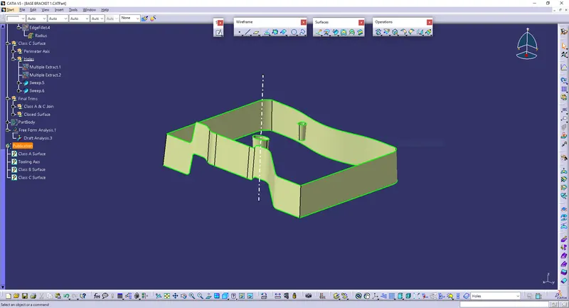
Joined and Closed Class A, Class B, and Class C Surfaces:
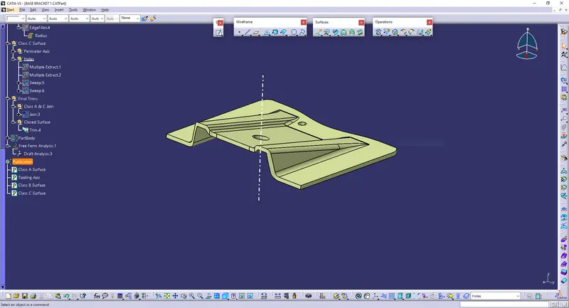
Solid Body:

Draft Analysis:
When a plastic component is made, we can observe that there is a draft angle given on each side from the base which is lesser than 90 degrees. This is because in the criteria of making a plastic material the mold should release the material when finished. if the mold surfaces are 90 degrees the material won't release from the mold because of friction due to contraction of material when cooled.
Before performing the analysis change material property to customizable view parameters and select the material option.
To perform draft analysis, click on Insert >> Analysis >> Feature Draft Analysis
- The color scale on the bottom visualizes, whether the draft angle meets the requirements or not by indicating the colors Green, Blue and Red.
Class A Surface Draft Analysis:
The Class A draft analysis is performed to check whether the input Class A Surface that has given to us is proper or not.
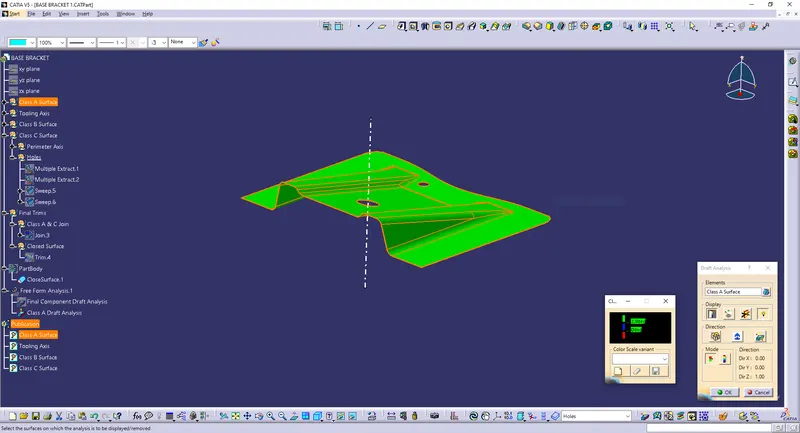
After the Draft analyzing if the Class A surface is shown in Green colour then the surface is in proper way.
Final Component Draft Analysis:
The Final component draft analysis is performed to check whether the created plastic component is ready to manufacturable.
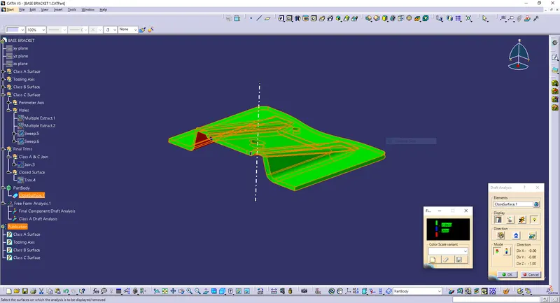
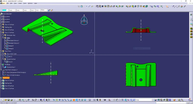
After the Draft analyzing the component is shown in Green colour then it is ready to manufacture.
Final Component in different views: