Week 8 - Challenge 4 - Bumper
REPORT FOR BUMPER DESIGN:
Aim : To create the plastic Bumper component through the given Class-A surface.
- To create the tooling axis for the given Class-A Surface meeting the requirements of the draft angle and at the end perform the Draft analysis on the final model.
Introduction:
A bumper is a structure attached to or integrated with the front and rear ends of a motor vehicle, to absorb impact in a minor collision, ideally minimizing repair costs. They are designed to absorb impact to the front and rear of vehicles and minimize low-speed collision damage. Today, standard passenger vehicle bumpers have a rigid reinforcing bar under the outer cover, with sections of compressible foam or plastic underneath. Plastic is the preferred material for modern car bumpers for several reasons. First and foremost, plastic is much lighter and more aerodynamic than metal, which improves the car's fuel efficiency.
Design Methodology:
The input of the product designer is in the form of the Class A Surface. The job of the product designer is to create the B and C surfaces keeping all the aspects for the mold.
Creation of Tooling Axis:
The tooling axis is the direction of drawing a sheet metal where the finished component is easily ejected on a particular direction and axis. In Molding, machine arrangement is given to open the mould along a direction which is known as Tooling Direction. In other words. The mould is built from two separate halves (Core and Cavity) and tooling direction basically defines the direction of mould pulls apart.
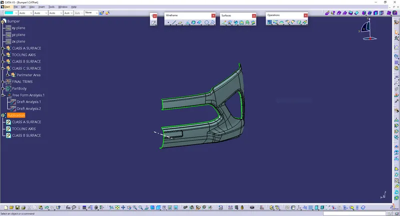
In the given model we are using the Normal To Surface method.
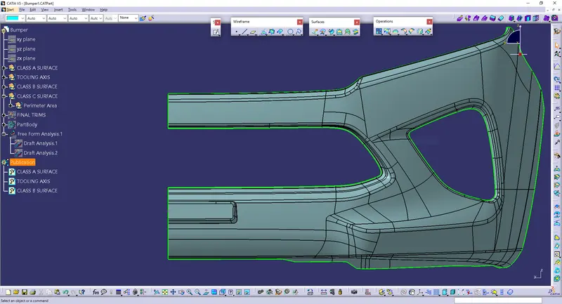
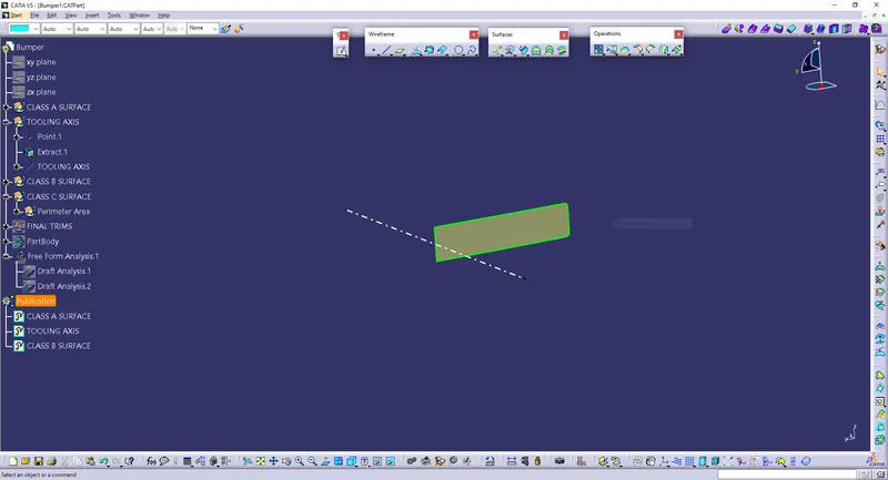
For creation of tooling axis, a point is inserted on one of the surface (number plate holder) of class A surface through which tooling axis can be drawn in X direction.
Class A surface with point on the surface:
Class A surface with Tooling Axis:
Material Selection
The material can be used for manufacturing Bumper is Acrylonitrile Butadiene Styrene (ABS). Because of its some features such as:
- The styrene provides the copolymer with a shiny, tough exterior.
- Provides quality surfaces and good resistance to chemical agents.
- A wide variety of adjustments can be made to enhance impact resistance, durability and heat resistance.
Also the Polypropylene material can be used to manufacture the Bumper. It has the features called: when compared to other plastics, PP has a higher melting point, making it safe to use in conjunction with hot temperatures. and also PP reduce the weight of vehicles compared to other material.
For manufacturing Bumper component the injection molding method can be adopted. It would be the right manufacturing method. Because it is a right way to create the exact moulding for the required product. This is a common method is used to produce a high volume of plastic parts like car parts etc. Products can also be made with increased flexibility to suit the needs of designers or engineers.
Class A,B & C Surface
Class A Surface:
It is the outermost aesthetic surface which is visible to customers (the outermost visible surface of a product).
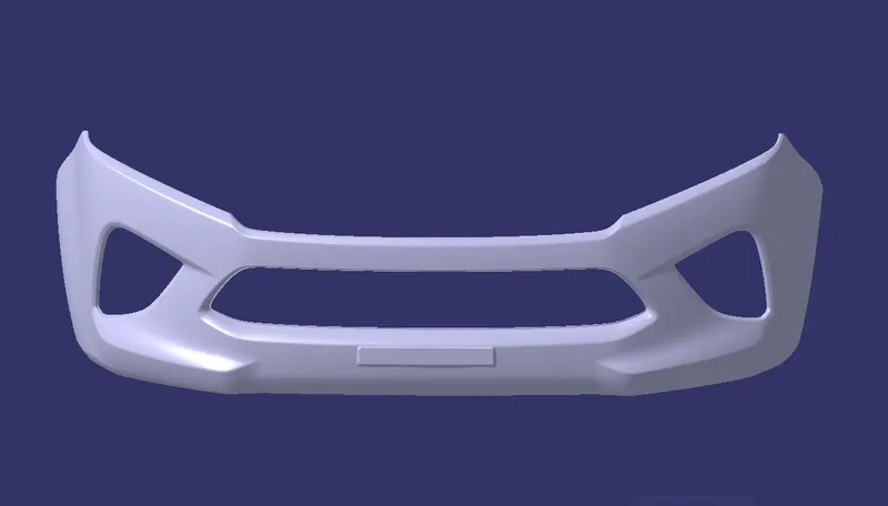
Here, class A surface is given:
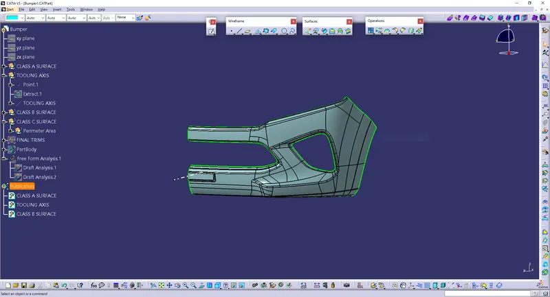
The class A surface is joined inorder to make it a single part and then checked the boundary to confirm that it is closed.
Class B Surface:
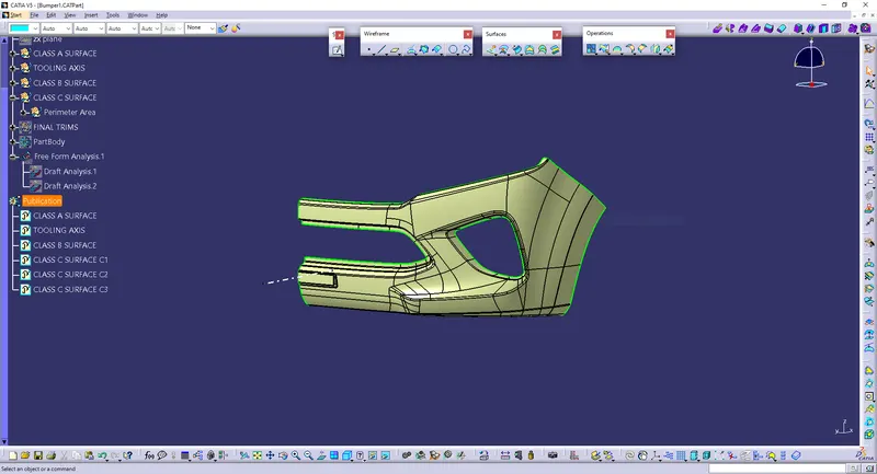
It is the offset of the class A surface at a particular distance. The offset distance depends on the thickness between Class A and Class B surface.
Here, the thickness given = 3mm.
Procedures to build class B surface:
- Offsetted the joined surfaces from class A to 3mm inorder to create class B surface.
- Extrapolated the offseted surfaces inorder to make sure all the surfaces are in contact.
- Trimmed the offsets to get an output same as class A surface
- Fillets are given to the required edges based on the thickness and curvature of the class A fillets.
Class C Surface:
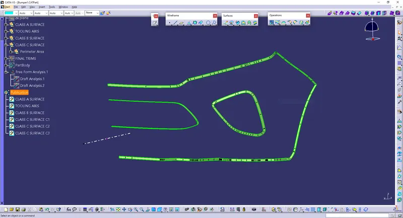
This surface connects the Class A and Class B surfaces. (Surface in between Class A & B surfaces)
Procedure to build Class C surface:
- Boundary of class A surface is extracted and then smoothcurved the boundaries
- Then that boundary is swept perpendicular to the Class A Surface until it gets coincided with the offseted class B surface.
Joined and Closed Class A,B & C surface:
After creating class B & C surfaces joining operation is done between class A and class C surfaces. Then, Class B surface is trimmed with joined Class A & C surfaces to get a whole closed single surface. Then in part workbench using closed body command, a solid body is generated.
Closed surface:
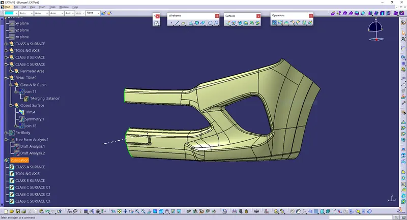
To create Solid body first, by using symmetry command the created half part of bumper is mirrored and then joined. Finally a whole closed bumper is created.
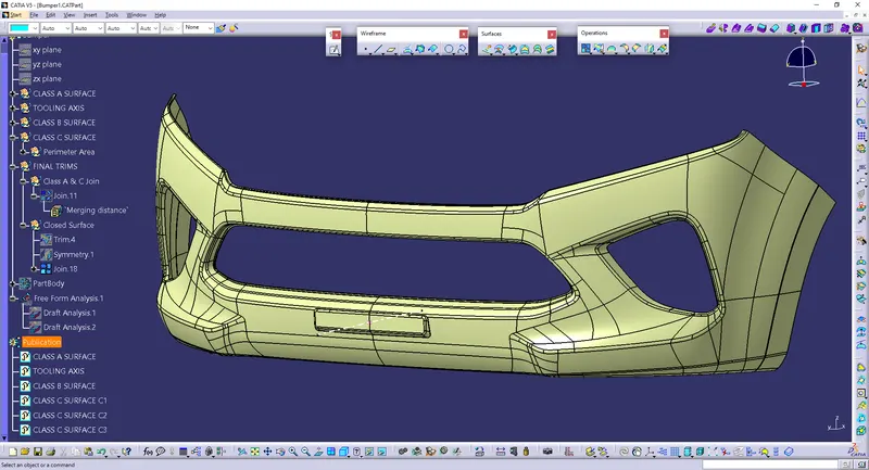
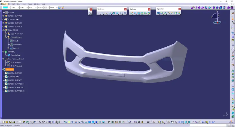
Solid Body:
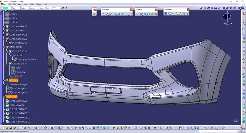
Draft Analysis:
In the criteria of making a plastic material, the mold should release the material when finished. if the mold surfaces are 90 degrees the material won't release from the mold because of friction due to contraction of material when cooled.The ejection of the part from mold depends on the draft. A zero draft can result in difficult or no ejection. It is recommended to add a draft of 3 degree or above inorder to remove it from the mold without any damage.
Procedure:
- Change the view mode to customize view parameters and give material as view mode.
- In the draft analysis toolbar, set the draft values and color (3 degree and above - green, 0 to 3 degree - blue, less than 0 - red).
- Drag and drop the axis system on the tooling axis and lock it.
- Perform draft analysis.
Draft analysis of Class A surface:
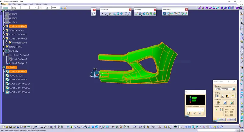
Draft analysis of final plastic component:
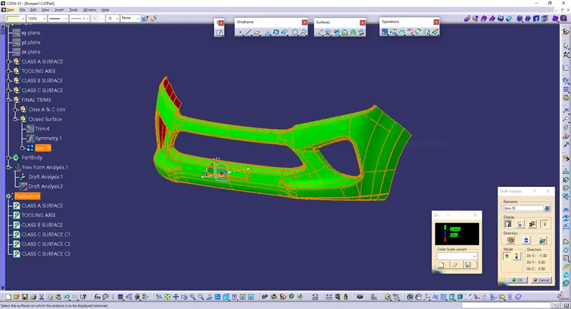
Hence by the above draft analysis images it is clearly shows that the designed plastic component is ready to manufacturable.
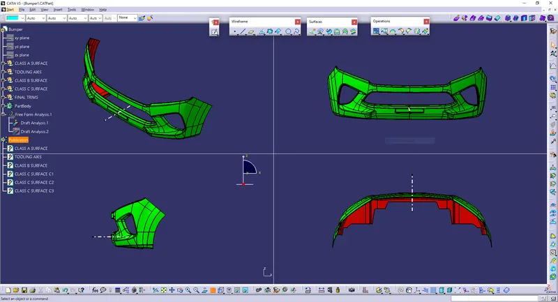
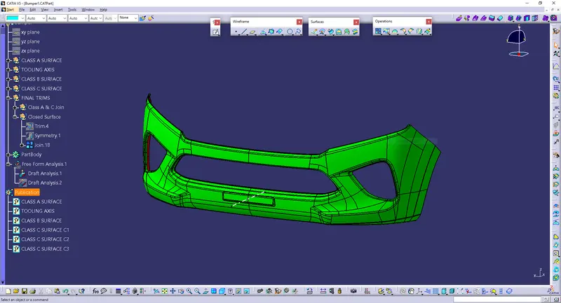
Screenshots of the solid model with the proper color code of the draft angle in various orientations:
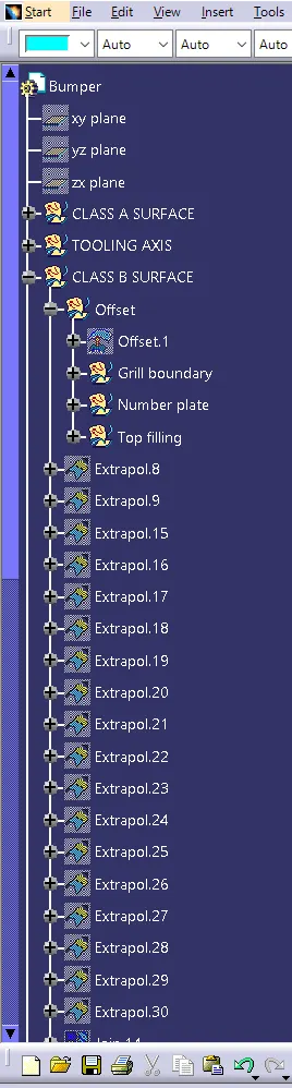
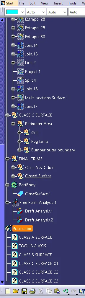
Tree Structure: