Week 8 - Challenge 6 - Core & Cavity Design
AIM:
- To Create the Core and cavity blocks for the switch bezel component.
DESCRIPTION:
1. CREATING TOOLING AXIS -
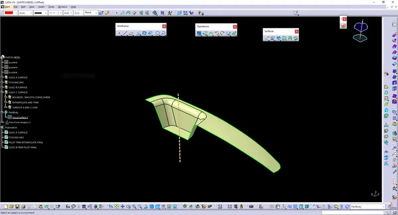
The Tooling Direction is the direction that the mold pulls apart. The mold is built in two separate pieces. You have a Cavity side and you have the Core side. The Core pulls apart from the Cavity and that's the Dye line or the Tooling Direction.
- Find the correct tooling axis where the material doesn't interfere with the tooling axis and all the elements can be created.
- Create an axis system using the center of the switch Bezel.
- NORMAL TO SURFACE was used to get the exact medium from the two sides to achieve the maximum positive draft angle.
-
3. DRAFT ANALYSIS
The Draft Analysis command enables you to detect if the part you drafted will be easily removed. This type of analysis is performed based on color ranges identifying zones on the analyzed element where the deviation from the draft direction at any point, corresponds to specified values.
- Before going to drat analysis go to customized view parameter under mesh check material and then click ok.
- Now for draft analyses go to insert analysis feature draft analysis.
- Use the compass to define the draft direction.
- In the color scale change the draft angle to 3 degrees.
- The component changes to green in the indication of the passing draft angle.
- Use a running point to check the angle of the component.
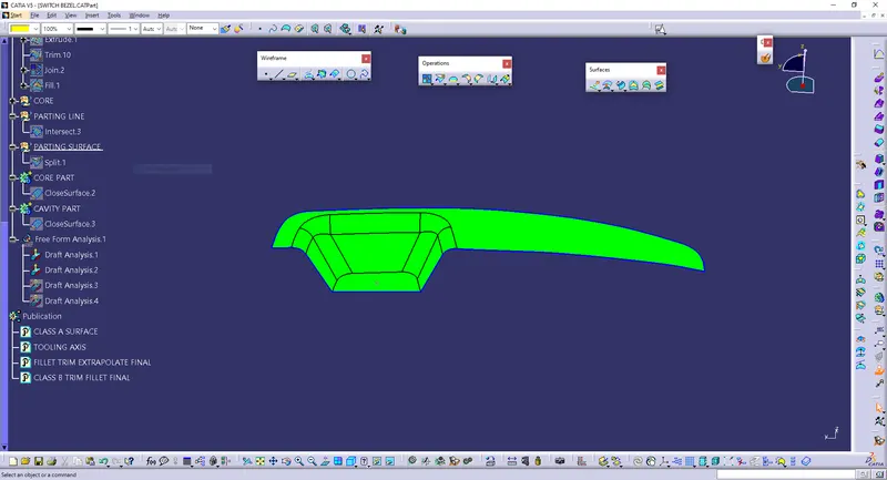
CLOSED PART :
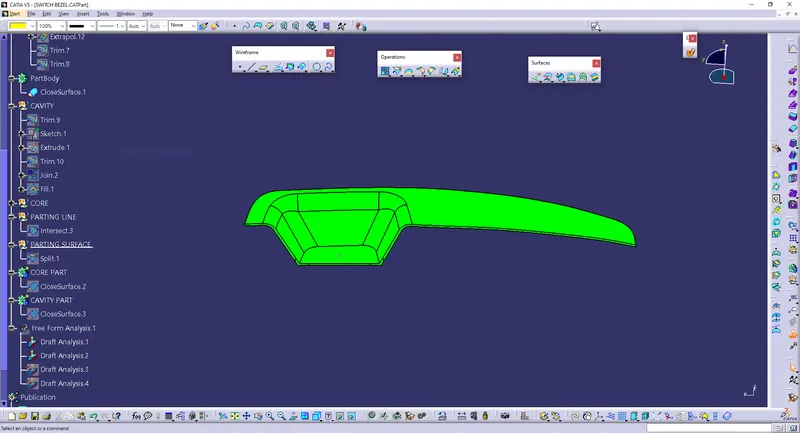
CORE ANALYSIS :
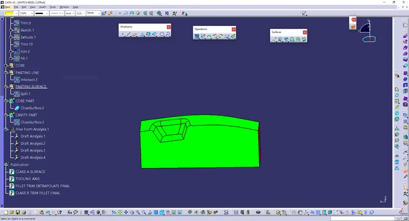
CAVITY ANALYSIS :
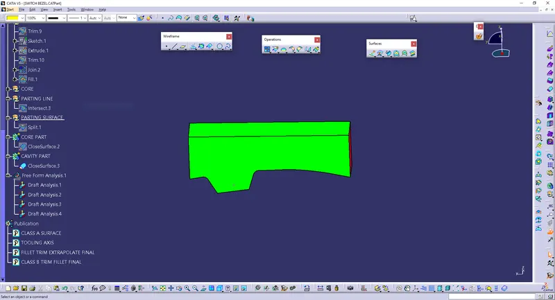
4. CORE DESIGN
- Core - A portion of the mold that goes inside a cavity to form the interior of a hollow part.
- Core-cavity - A term used to describe a mold created by mating A-side and B-side mold halves.
- Core is a preformed, bonded, sand insert placed into the mold to shape the interior of a casting or a part of the casting that cannot be shaped by the pattern.
- Core is the male part that forms the internal shape of the molding.
- Cores are often used to create hollow sections or cavities in a casting.
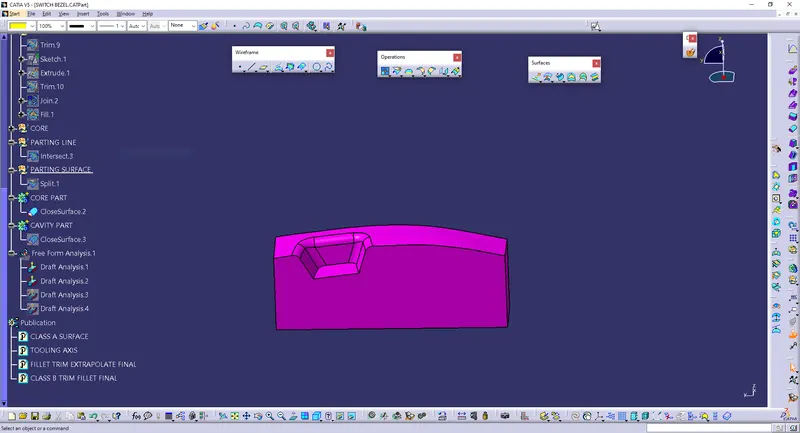
5. CAVITY DESIGN
- A mold is a hollow form typically made from stainless steel that has plastic injected into it to manufacture a plastic part.
- The plastic is inserted into the mold cavity, which is a hole in the mold shaped like the desired part.
- The cavity is the female part that forms the external shape of the molding.
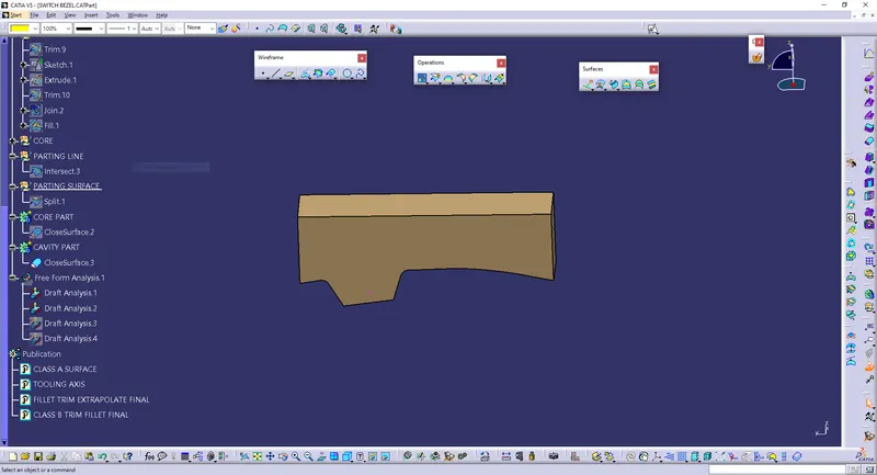
6. PARTING LINE
- A parting line is an inevitable part of injection-molded products.
- It is the line of separation between where two halves of a mold meet.
- It manifests itself on injection molded parts as a line that runs the entire perimeter of the part.
- In most parts, it is just a line that runs straight down the middle.
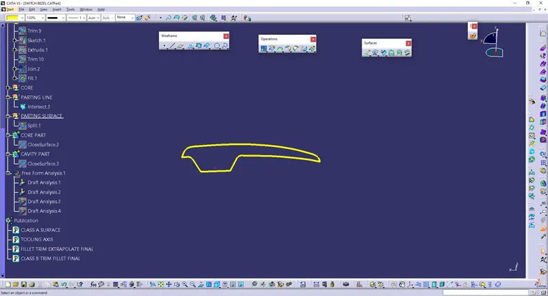
7. PARTING SURFACE
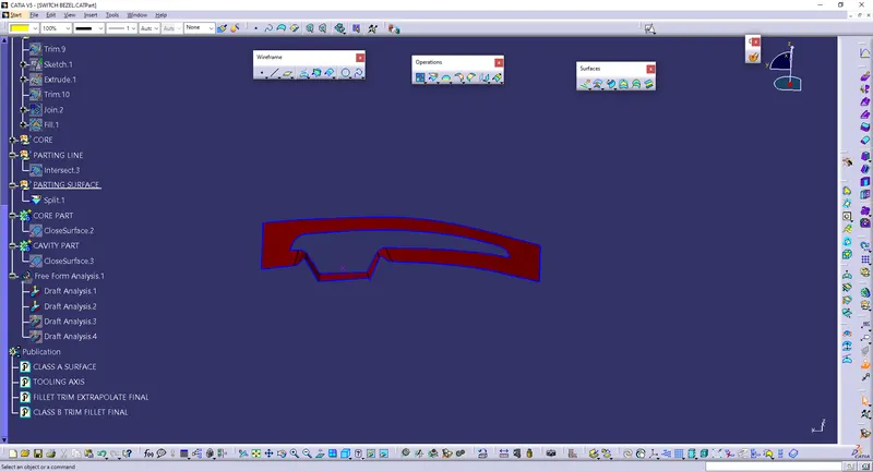
- Generally injection mold has two major components: the movable half and the fixed half, during the injection molding process, these two halves are pressed tightly from a sealed hollow to avoid melt flow leakage and maintain certain holding pressure, the pressed surface is called parting surface, usually, parting surface are the biggest projection outline of the part.
CONCLUSION:
- The Core and cavity blocks for the switch bezel component are created.