Week 8 - Challenge 2 - Switch Bezel Design
A detailed report of Switch Bezel Design
AIM:
Create the Switch Bezel component through the given Class-A surface. To begin with, the tooling axis for the given Class A Surface should be created meeting the draft angle requirements and performing the Draft analysis on the model at the end.
TOOLING AXIS:
There are three types of tooling axis :
- with respect to the axis (X, Y, Z)
- normal to the surface
- bisecting surface
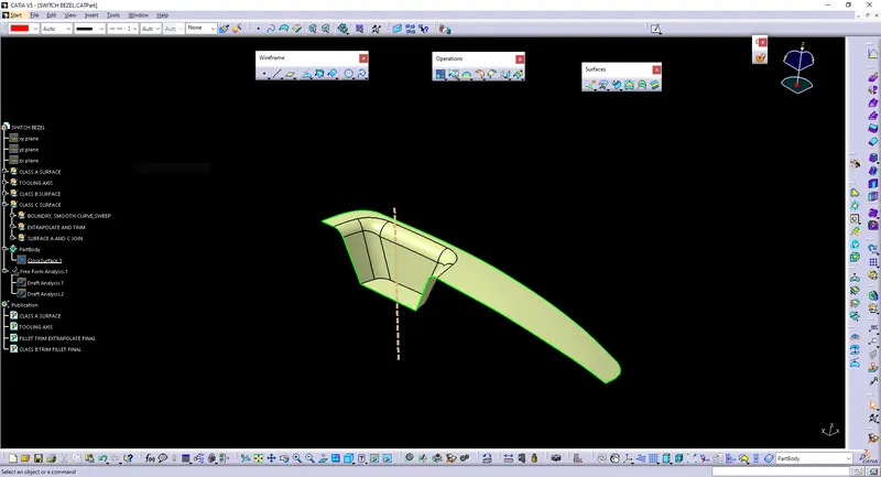
We should observe and study the class A surface to create the 'Tooling Axis' for the switch bezel. First, we create a tooling axis along the X, Y, and Z axis but all the features are not visible while taking those axes Therefore the main tooling axis is normal to the surface (base surface)and only possible because it is a tilted profile.
MATERIAL SELECTION :
Polypropylene (PP)
- Polypropylene (PP) is one of the most commonly used thermoplastics in the world.
- It has good chemical resistance and electrical properties, a hard and tough material with water absorption.
- Easy to manufacture
- Fast crystallization, fast cooling.
- Better temperature resistance than HDPE
- Lower density than HDPE
DRAFT ANALYSIS OF CLASS A :
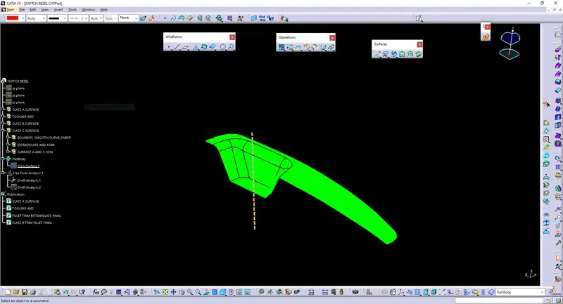
Draft analysis is required to check if a part has required a draft or not. The draft is required so that a part can be ejected from its mold. The Draft analysis using the Featured Draft Analysis tool in the tools. Then after opening the draft analysis toolbox go for the compass and place the compass aligned to the tooling axis and click on the lock symbol after aligning further click on the surface it shows green color means it is the correct draft angle blue color means it is some minor defect but it is allowable to manufacture else red shows it cant be manufactured.
CLASS B SURFACE:
It is the invisible Surfaces. Surfaces mostly don't have textures, The surface needs to be created according to class-A surface.
having all features(Rib,boss,snap etc) in B-side surface only.Surfaces which is having TANGENT CONTINUITY ARE CALLED class-B.
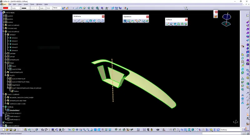
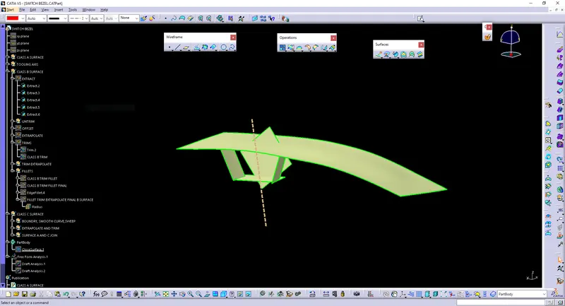
initially extracting the right side using the extract option from the Class A surface. Then perform Extrapolate in order to increase the length now trim the surfaces to the required surfaces then Offset the surface in order to get the required thickness which is 2.5 Similarly, offset it to the desired value and now trim in order to get the required surface now fillet the surface to the required amount using fillet rule then the value is 17.5 and 11.5 in the respective place.
OPERATIONS DONE IN CLASS B SURFACE:
1. EXTRACT:
2. UNTRIM:
3. OFFSET:
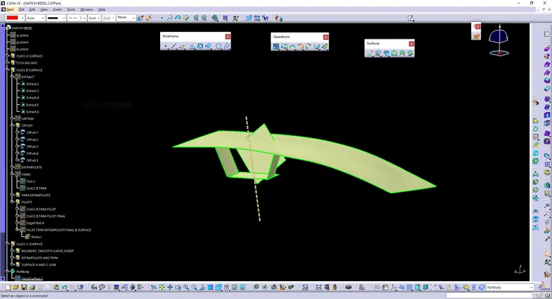
4. EXTRAPOLATE:
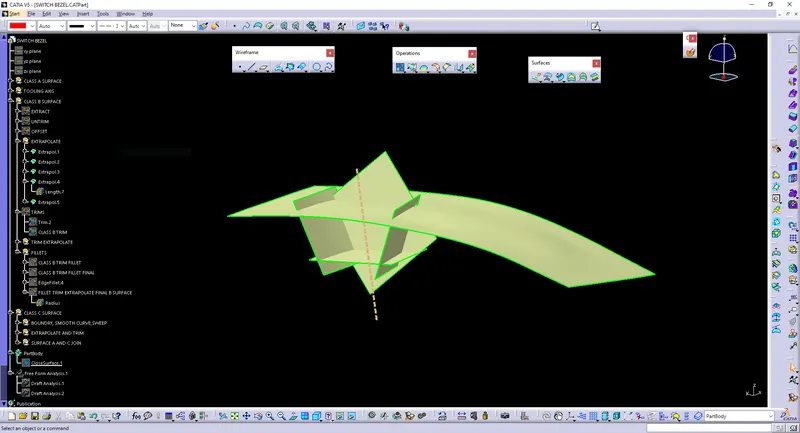
5.TRIM :
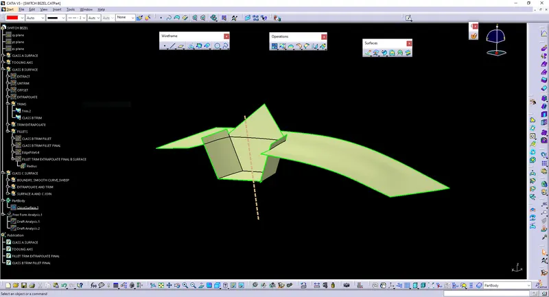
6. FILLETS :
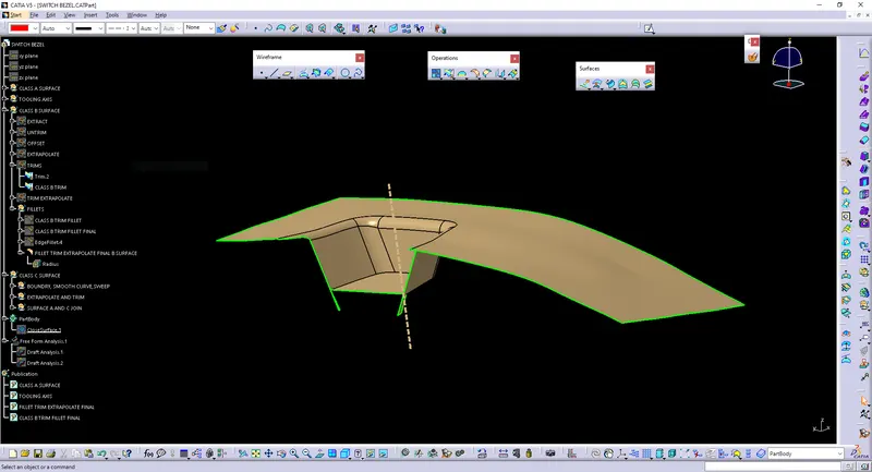
CLASS C SURFACE:
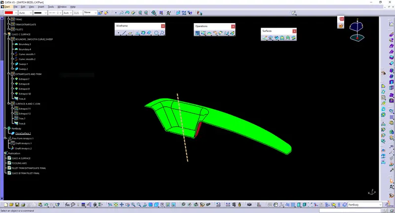
It is the combination of Class A and Class B . it connects the class A and class B surfaces. select the outer boundary and tooling axis surface gives 3 deg in the angle (the draft angle for a plastic component is 0.5 to 3 deg).
OPERATIONS DONE IN CLASS B SURFACE:
1. BOUNDRY AND SMOOTH CURVE :
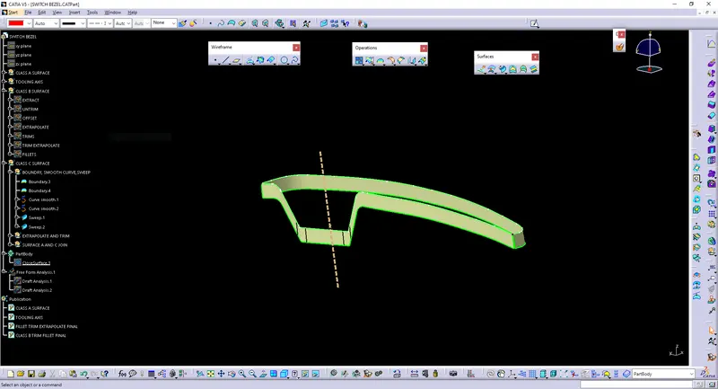
2. EXTRAPOLATE AND TRIM :
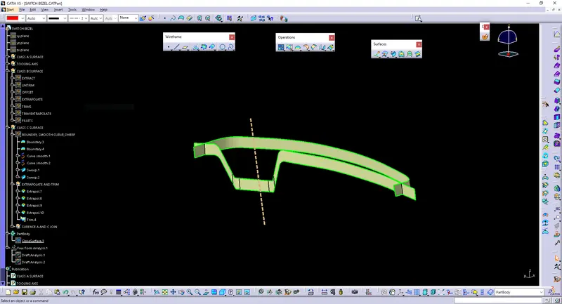
3. FINAL TRIM:
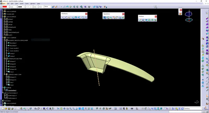
SOLID PART :
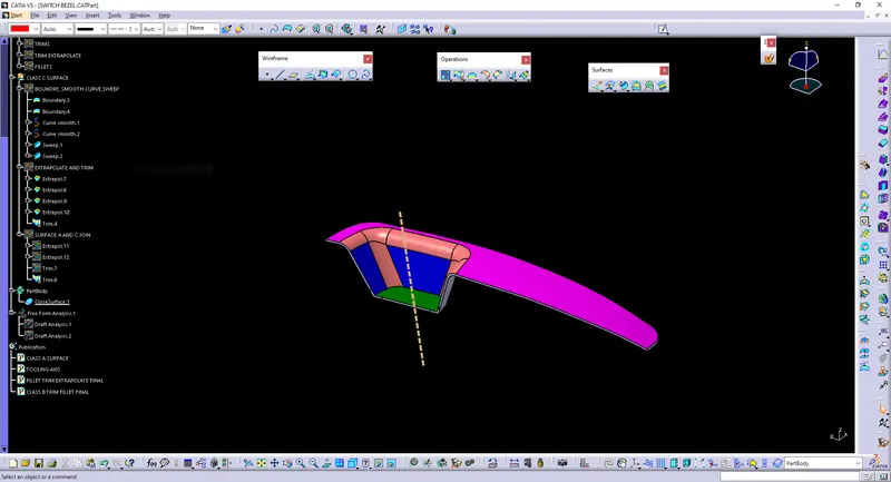
DRAFT ANALYSIS OF THE WHOLE PART(SOLID PART):
Draft analysis is required to check if a part has required a draft or not. the same procedure as the CLASS A SURFACE draft analysis but we have done it here for the solid component
CONCLUSION:
The Design of the Plastic Component - switch bezel from Class A is completed using concepts of Draft angle, Draft Analysis, Tooling Axis, Class B, and Class C creation, and converting the Closed surface to a solid part.