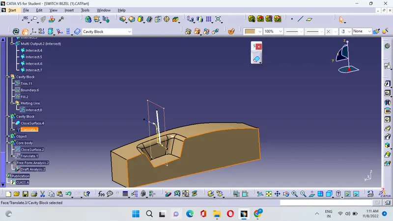
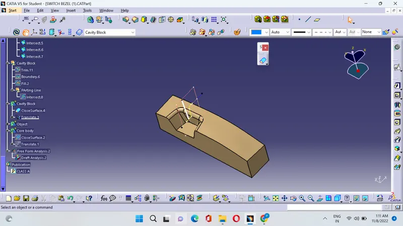
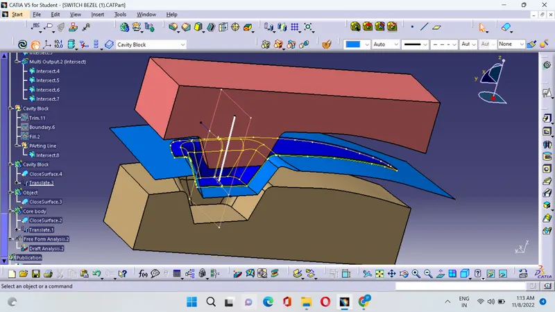
Week 8 - Challenge 6 - Core & Cavity Design
REPORT :
Parting Line : It is defined has the surface that divides the mould into two halves they are the core and the cavity
Parting Surface :The Parting surface is the seperable contact surface that seperates the mould to remove the product and the congeleated material from the pouring system.A mould may have one or more parting surfaces depending on the need.The parting surface may be perpendicular to the closing direction,or parallel or inclined to the closing direction.
Tooling Axis : It is simply defined has the axis in which direction the majority portion of the surface clears is knownhas the tooling axis.
Tooling Direction : The direction in which the mould pulls apart.The mould is pulled in two seperate pieces.Basically you have a cavity side and a core side.The core pulls apart from the cavity side and thats the dyeline or the tooling direction.
TOOLING AXIS CREATION :
1. First insert a point on the surface of the class A by extracting the base.
2. The selected surface is in such a way that the majority portion of the object have to be cleared and the remaining portion is in such a way that it can be cleared in the tooling direction.
3.Firstly take a line on the point create a fake tooing axis along the y axis and then take intresect on the yz axis you will get a line from that line create an angle of 3 Degree to this line.
4.Now take intresect on zx axis you will get two lines along the axis and create a line from these two lines using besecting method.
5.Finally take the two lines from both the axis created and create the final bisecting line from these two lines.That is the tooling Axis.
Draft Analysis :
1.Green color indicates that the degree is from 0 to 3 degrees
2.Red color indicates that the degree is from 0 to 2.9 Degrees
3.Blue color indicates that the degree is from 0 to negative
CORE :
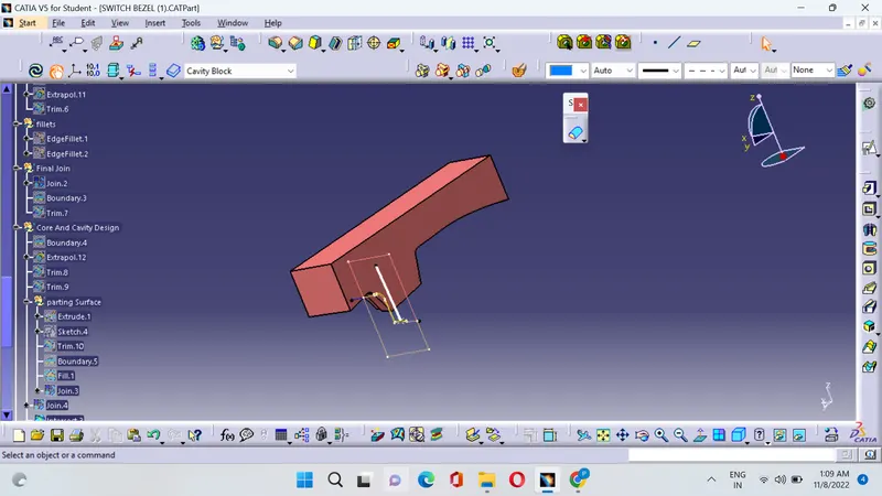
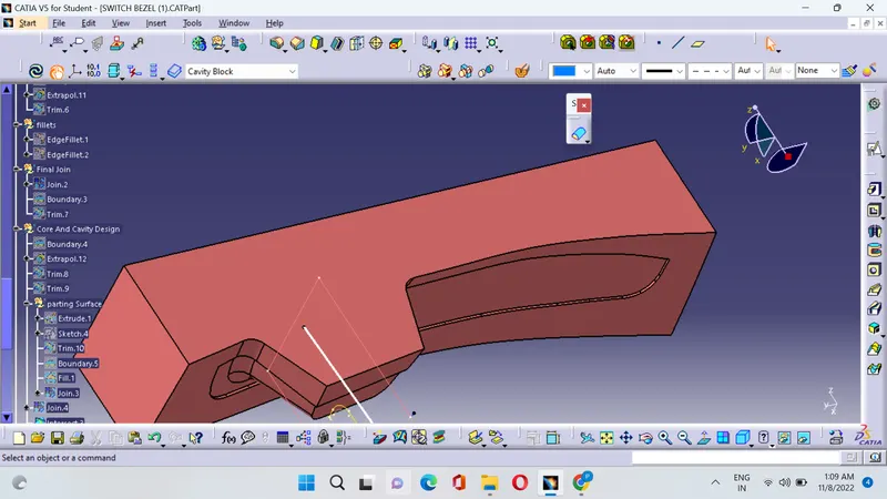
CAVITY :